 Lei Wang
 Jun Zhou2,3
 Yintong Guo
 Xuehang Song
 Wuhao Guo
94% of researchers rate our articles as excellent or good
Learn more about the work of our research integrity team to safeguard the quality of each article we publish.
Find out more
ORIGINAL RESEARCH article
Front. Earth Sci., 26 August 2022
Sec. Structural Geology and Tectonics
Volume 10 - 2022 | https://doi.org/10.3389/feart.2022.952655
This article is part of the Research TopicUnconventional Reservoir GeomechanicsView all 16 articles
Hydraulic fracturing is widely implemented in the exploration of marine shale gas. Affected by various geological and engineering factors, gas production after stimulation is not always satisfactory. To reveal the influential effect of multiple factors, laboratory hydraulic fracturing experiments are performed on Longmaxi marine shales by considering key parameters (deviatoric stress, confining pressure, pumping rate, fracturing fluid type, and bedding angle). The variation of breakdown pressures and the characteristics of hydraulic fractures are recorded and analyzed. The results show that the breakdown pressure increases with increasing deviatoric stress, confining pressure, pumping rate, and viscosity of the fracturing fluid. As the bedding angle varies from 0° to 90°, the breakdown pressure declines first and increases again. Furthermore, parameter sensitivity analysis indicates that geological factors (confining pressure, bedding angle, and deviatoric stress) would largely determine the breakdown pressure, while engineering factors (pumping rate, fracturing fluid type) could only affect it to a lesser extent. Computed tomography measurements show that natural fractures, originating from tectonic shear failure, could possess greater width than tension-dominated hydraulic and bedding fractures. Statistical analysis shows that the length of the hydraulic fractures alone is only approximately 150 mm. However, the fully activated natural and/or bedding fractures could help substantially increase the total fracture length to 600 mm. Low deviatoric stress, low confining pressure, low viscous slick-water, and high bedding angle are conducive to activating natural and bedding fractures and forming a complex fracture network. The aforementioned findings are valuable for the optimal design of field hydraulic fracturing.
Organic-rich shales are important hydrocarbon-bearing source rocks and thus are targets for shale oil and gas exploration worldwide. In China, the geological resources of shale gas are estimated to be approximately 110×1012 m3, with recoverable gas reserves of ca. 20×1012 m3 (Zou et al., 2019). According to the sedimentary environment, organic-matter-rich shales can be further divided into three types: marine, transitional, and lacustrine shales. Shales of marine origin, with a ca. total of 9×10¹² m3 of recoverable resources is the most promising type to make a breakthrough. After 10 years of exploration and practice in the marine shales of the Wufeng–Longmaxi Formation, China, has become one of the few countries achieving industrial shale gas exploitation (Ma et al., 2018). By the end of 2020, the annual production of shale gas exceeded 200×108 m3 (Zhang et al., 2021).
In view of the fact that the porosity and permeability of shale reservoirs are extremely low, hydraulic fracturing is an effective technology to achieve commercial development (Zou et al., 2017). Ideally, hydraulic fractures initiate from the borehole at an acceptable breakdown pressure and propagate into the reservoir, fully activating natural fractures and bedding and forming a complex fracture network (Xu et al., 2018). The fracturing effects are controlled by various factors, which can be roughly divided into geological and engineering categories. In-situ stress, the development of natural fractures, and the bedding structure are major geological factors closely related to hydraulic fracturing. The pumping procedure and fracturing fluid type are key engineering factors that can be controlled to regulate hydraulic fracture propagation.
To reveal the influence of various factors on the initiation and propagation of hydraulic fractures in marine shales, former researchers performed laboratory hydraulic fracturing tests. In the work of Tan et al. (2017), the vertical propagation behavior of hydraulic fractures in laminated shale formations was investigated. In situ stress, injection rate, and fluid viscosity were included in the experimental design. Hou et al. (2019) proposed a novel alternating fluid injection method with guar fluid and slick water to form a large, complex fracture network. In addition, Hou et al. (2018) also focused on the condition of a high horizontal stress difference in deep shale formations. Zhang et al. (2019) and Cai et al. (2020) both discussed the anisotropic effects of shale on fracturing. In the aspect of fracture morphology analysis, an optical scanner was used to reconstruct the rough fracture surface at the macroscale (Song et al., 2019; Yang et al., 2022), while scanning electron microscopy (SEM) was applied to observe hydraulic fractures at the local microscale (He et al., 2020). Computed tomography (CT) scanning is another powerful tool for 3-D hydraulic fracture characterization (Guo et al., 2014; Zhang et al., 2017; Li et al., 2019). Referring to the concept of “Stimulated Reservoir Volume” (SRV) (Fisher et al., 2004; Mayerhofer et al., 2010), “Stimulated Rock Area” (SRA) is proposed to quantitatively evaluate the laboratory hydraulic fracture networks (Hou et al., 2014). The aforementioned literature review showed that previous research mainly focused on one or some factors affecting hydraulic fractures. Few studies have compared and analyzed multiple factors at the same time. Parameter sensitivity analysis of the breakdown pressure is also rarely reported. The contributions of natural fractures and bedding structures to improving the stimulation effects need to be further evaluated.
In this study, an outcrop of the Longmaxi marine shale is collected. Laboratory hydraulic fracturing experiments are performed, involving multiple factors, such as deviatoric stress, confining pressure, pumping rate, fracturing fluid type, and bedding angle. The breakdown pressure and fracture morphology are recorded and analyzed, comparatively. Based on the fracture classification, width and length measurements are implemented. Parameter sensitivity analysis on the breakdown pressure, contribution of natural/bedding fractures, and influence of heterogeneity are discussed.
The sampling site of the marine shale outcrop is located in Wulong District, Chongqing, China (Figure 1A), approximately 70 km from the Fuling gas field, the first large-scale shale gas field in China. The outcrop is the natural extension of the Lower Silurian Longmaxi Formation, which is one of the main targeted shale gas reservoirs in southern China. Stratigraphic consistency guaranteed the representativeness and effectiveness of the mineral composition, mechanical properties, and laboratory hydraulic fracturing results derived in this study. Considering that long-term atmospheric and microbiological factors would exert a deterioration effect on the outcrop shale, making it softer and more broken, the upper-weathered layer is removed as much as possible and the bottom fresh shale is collected during sampling.
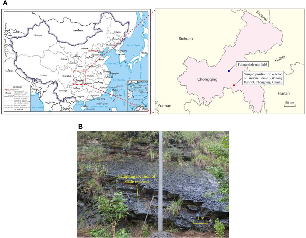
FIGURE 1. Outcrop collection of marine shales: (A) geographical position and (B) field sampling.
To reveal the mineral composition of the collected outcrop, shale fragments are ground into a powder sample for X-ray diffraction (XRD) analysis. In addition, two types of cylindrical specimens (φ50×100 mm and φ50×25 mm) are also prepared for rock mechanical tests. Specifically, five samples with dimensions of φ50×100 mm are designed for uniaxial compressive tests, which can provide the mechanical properties of uniaxial compressive strength, Young’s modulus, and Poisson’s ratio. It should be noted that the bedding of the shale is perpendicular to the axis of the cylinder for this type of specimen. Ten specimens (φ50×25 mm) were used for Brazilian indirect tensile experiments, which could evaluate the tensile strength of the shale matrix and bedding. The shale bedding is parallel to the axis of the cylinder for this type of sample.
The sample preparation for hydraulic fracturing tests is relatively complex. First, approximately twenty cylindrical specimens, with a diameter of 100 mm and height of 200 mm are prepared from shale outcrops. Here, the bedding angle (β) is considered, which is the angle between the bedding plane and the vertical axis of the cylinder. For most of the specimens, the bedding is along the horizontal plane (β=90°), while the bedding planes of several other specimens are inclined with different bedding angles. Detailed information on the sample orientation is provided in Table 1. Second, a small hole, with a diameter of 12 mm and depth of 120 mm, is drilled into the center of one end face by using a special slender drill bit (Figure 2A). Third, the steel pipe (Figure 2B), with a diameter of 6 mm and height of 110 mm, is placed in the small hole to a depth of 100 mm. The surface of the steel pipe is spirally prefabricated to increase the bonding strength with the sealant. Then, the epoxy resin sealant (Figure 2C) is poured into the annulus. After the sealant is set, an open hole with a height of 20 mm is reserved inside the specimen. Some prepared specimens and the detailed dimensions are provided in Figure 2D and Figure 2E, respectively. It should be noted that the steel pipe is 10 mm higher than the end face of the specimen, and a sealing ring is added to guarantee the sealing performance between the steel pipe and indenter.
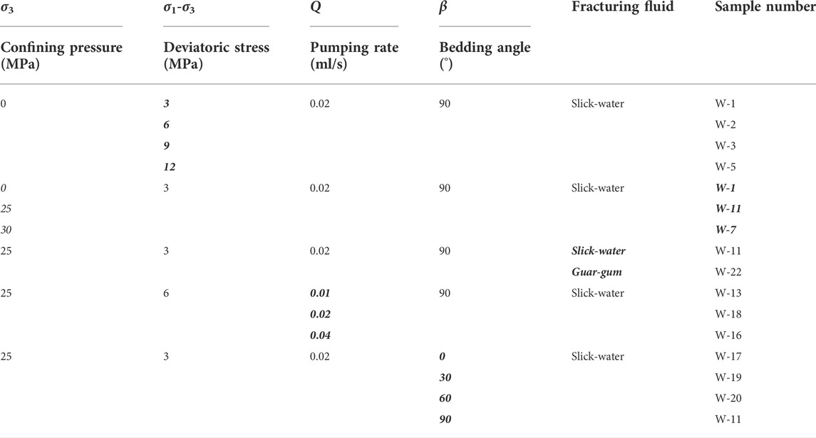
TABLE 1. Experimental scheme of laboratory hydraulic fracturing considering multiple factors.
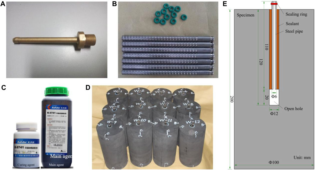
FIGURE 2. Sample preparation for hydraulic fracturing: (A) drilling bit, (B) spirally prefabricated steel pipes and sealing rings, (C) epoxy resin sealant, (D) some prepared specimens, and (E) dimensional details of the specimen.
The mineral composition analysis was implemented on a D8 Advance X-ray diffractometer. Uniaxial compressive and Brazilian indirect tensile tests were conducted on MTS815 and RMT-150C rock test systems (Wang et al., 2020), respectively. Considering that the aforementioned experimental systems are conventional test instruments, the detailed introduction is omitted. A specific description of the laboratory hydraulic fracturing system is provided in the following section.
As shown in Figure 3A, the laboratory hydraulic fracturing system mainly consists of three parts. The first part is a servo-controlled triaxial testing machine, which can provide steady axial compressive stress (σ1) and confining pressure (σ3) on the specimen to simulate vertical and horizontal in-situ stresses, respectively. The designed maximum axial force is 2,000 kN, and the limit of confining pressure is 140 MPa. The second part is a plunger pump, which can transport the fracturing fluid into the specimen at a given flow rate and achieve the initiation and propagation of hydraulic fractures (Guo et al., 2020). The controlled flow rate range is 0.01–10 ml/min, the maximum output pumping pressure is 70 MPa, and the maximum storage volume is 300 ml. The third part is the control and data acquisitions system, which is responsible for the control and acquisition of key parameters, such as axial stress, confining pressure, and pumping pressure. The aforementioned three parts cooperate with each other and perform their own functions.
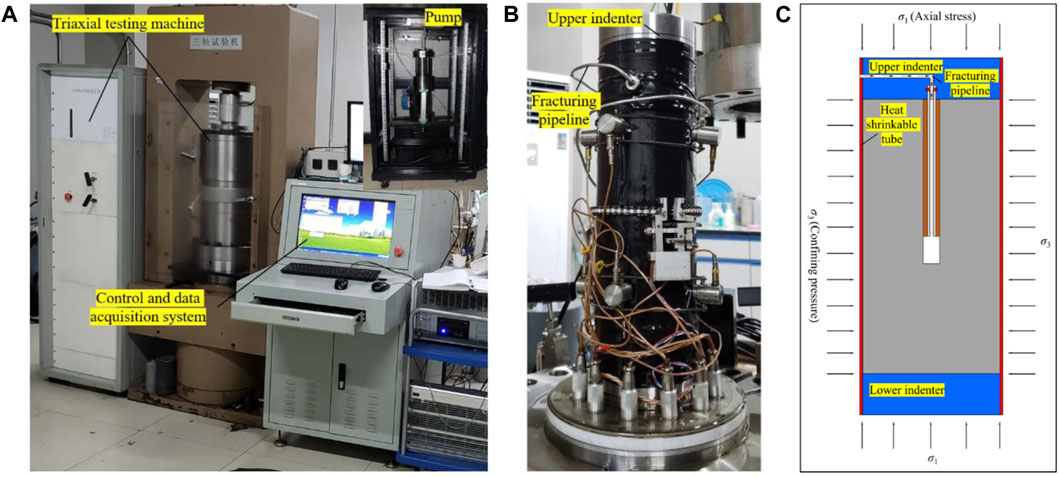
FIGURE 3. Laboratory hydraulic fracturing system: (A) main experimental equipment, (B) assembled sample, and (C) stress state and fluid transportation.
The main test procedures are as follows:
1) The assembly of the prepared specimens. As illustrated in Figure 3B, the prepared specimen was placed between the upper and lower indenters. Wrap up the combined indenters and the specimen with a heat shrinkable tube. Connect the fracturing pipeline to the upper indenter. Deploy the related sensors.
2) The exertion of axial and confining stresses. The triaxial chamber was placed, and the inside was filled with hydraulic oil. The confining pressure was exerted to the set value and then the axial force was applied to the set value (Figure 3C). The axial stress and confining pressure would remain stable during the next hydraulic fracturing stage.
3) The injection of the fracturing fluid. With the displacement of the plunger, the fracturing fluid flows into the specimen along the pipeline at a constant rate. The pressure inside the specimen gradually increases and reaches the peak value, along with the formation of hydraulic fractures. The whole pressure‒time curve is recorded.
4) The characterization of hydraulic fractures. After the drop in pumping pressure and the full extension of the hydraulic fractures, the post-test specimen was removed, and the characteristics of the induced hydraulic fractures were recorded, described, and analyzed in detail. CT scanning was implemented on specimens with typical hydraulic fracture morphologies.
In uniaxial compressive experiments, five samples are tested by controlling a constant axial displacement rate of 0.12 mm/min. The uniaxial compressive strength, Young’s modulus, and Poisson’s ratio could be measured. In Brazilian indirect tensile tests, the ten specimens are divided into two equal groups. Samples in one group are loaded along the bedding structure, while the other group is loaded perpendicular to the bedding. Therefore, the tensile strengths of both the bedding and matrix could be acquired.
Considering that the primary objective of this study is to investigate the features of the hydraulic fractures in marine shales, five primary controlling factors are selected in the experimental design. They are the deviatoric stress (σ1-σ3), confining pressure (σ3), pumping rate (q), fracturing fluid type, and bedding angle (β). Comprehensively considering the in situ geological and field-fracturing operation parameters, the similarity criterion (De Pater et al., 1994; Crosby et al., 2002), and the capacity of the laboratory hydraulic fracturing system, the detailed experimental scheme is designed and listed in Table 1.
From the XRD results, the outcrop shale mainly contained quartz, accounting for 69.78%. The content of albite ranked second and was 11.40%. The illite content was 10.93%, which was in the third place after quartz and albite. In addition, small amounts of calcite, pyrite, and dolomite were also detected (Table 2). The total content of brittle minerals (quartz+albite+calcite+dolomite) was nearly 90%, exhibiting great brittleness (Jarvie et al., 2007; Jin et al., 2015; Rahimzadeh Kivi et al., 2018).

TABLE 2. Mineral composition of outcrop shales.
Laboratory mechanical tests show that the values of uniaxial compressive strength are distributed between 81.6 and 108.4 MPa, and the average value is 98.5 MPa. The values of Young’s modulus and Poisson’s ratio are 22.29–26.96 GPa (average value 24.11 GPa) and 0.17–0.24 (average value 0.20), respectively. Brazilian indirect tensile tests indicated that the tensile strengths of the matrix and bedding were 13.0 and 8.5 MPa, respectively, with a specific value of 1.5. This type of marine shale shows high strength, high Young’s modulus, and low Poisson’s ratio, which reflect strong brittleness. The collection of mechanical parameters is provided in Supplementary Table A1.
Deviatoric stress (σ1-σ3) is defined as the difference between axial stress (σ1) and confining pressure (σ3). Under a normal fault stress state (σV > σH > σh), vertical stress (σV) could be simulated by axial stress (σ1), and horizontal principal stress (σH, σh) could be represented by confining pressure (σ3) in the experimental context. When the value of confining pressure remains constant, the variation in deviatoric stress could influence the interaction between hydraulic fractures and bedding structures.
As depicted in Figure 4, the pumping pressure increases slowly in the initial pumping stage, and then gradually accelerates with the continuous injection of the fracturing fluid. After reaching the peak point, the pressure curve drops sharply to zero in the absence of the confining pressure constraint. The breakdown pressure (pressure value at the peak point) (Yew, 1997) grows approximately linearly with increasing deviatoric stress. Specifically, at a deviatoric stress of 3 MPa, the breakdown pressure is 16.4 MPa. The value of pb nearly doubles and reaches 30.95 MPa, when the deviatoric stress is set to 12 MPa.
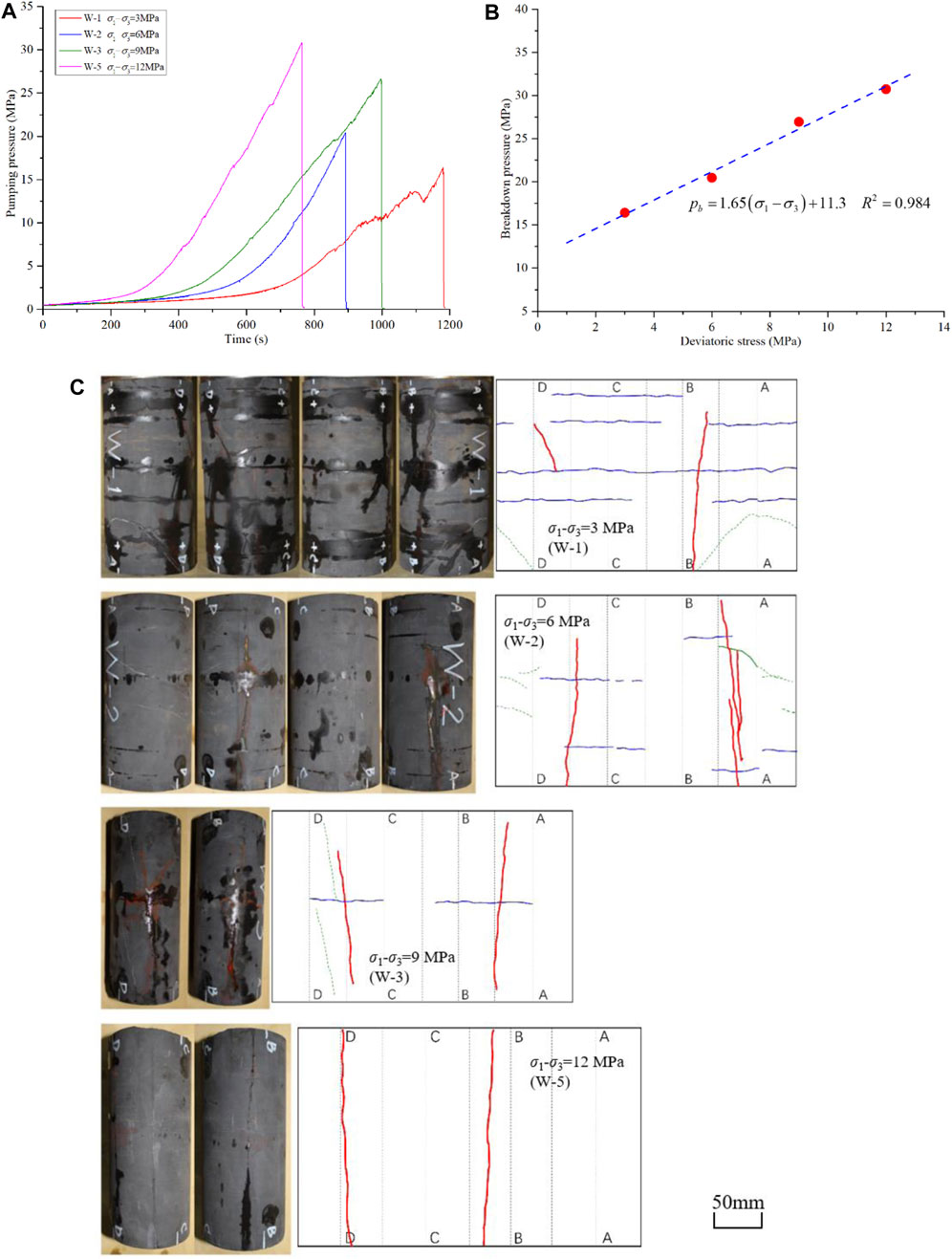
FIGURE 4. Pumping pressure and fracture morphology under different deviatoric stresses: (A) pumping pressure vs. time, (B) breakdown pressure vs. deviatoric stress, and (C) photographed and depicted surface distributions of the hydraulic fractures. (Red solid curves denote the main hydraulic fractures. Blue solid curves represent the opened bedding structures induced by hydraulic fracturing. Green dotted lines are closed natural fractures, and the part activated by hydraulic fracturing is replaced by green solid lines. Black dotted lines divide the whole area into eight equal parts, which are used to locate the relative position of the fractures.).
The fracture morphology is also sensitive to the variation in deviatoric stress. At a deviatoric stress of 3 MPa (Figure 4C), double wing hydraulic fractures are formed in the vertical direction, with one side extending more fully. In addition, four bedding planes are also completely disturbed to crack. The hydraulic fractures and opened bedding planes are interconnected to present a relatively complex fracture morphology. As the deviatoric stress increases to 6 MPa, the main hydraulic cracks are still double wing-shaped. However, the opening of bedding structures is significantly inhibited. Although four bedding fractures can be observed, they are sparsely distributed and partially opened. It is noteworthy that a small portion of the filled natural fractures is activated and connected with the main hydraulic fractures. When the deviatoric stress reaches further to 9 MPa, the cracking of the bedding planes is further restricted in both quantity and degree. Only one bedding plane is partially opened. Under the condition of σ1-σ3=12 MPa, hydraulic fractures only propagate in the vertical direction, and the bedding structure remains intact throughout the whole hydrofracturing process. Therefore, the increase in deviatoric stress could observably hinder the cracking of bedding and reduce the complexity of the hydraulic fracture morphology.
The deviatoric stress usually grows with increasing burial depth. For deep shale gas resources (burial depth ≥3500 m), the absolute value of the vertical in situ stress could exceed 87.5 MPa (assuming a stress gradient of 2.5 MPa/100 m in the vertical direction), and the deviatoric stress would easily exceed 10 MPa. It could be inferred from the experimental results that the opening of the bedding fractures would be severely restricted, and the morphology of the hydraulic fractures would tend to be simple in deep shale formations. It would be difficult to form a complex fracture network similar to that in the shallow strata. The reservoir stimulation strategy should pay more attention to cyclic injection (Zhou et al., 2017; Zhou et al., 2019) and cluster spacing reduction.
The exertion of confining pressure could be regarded as underground horizontal in situ stress. With increasing burial depth, the horizontal in situ stress grows synchronously, which inevitably affects the breakdown pressure and geometry of the hydraulic fractures.
As provided in Figure 5, the effect of confining pressure could greatly improve the pressure required to fracture the specimen. In the unconfined situation (σ3=0 MPa), the breakdown pressure is just 16.42 MPa. When the confining pressure is set to 25 MPa, the breakdown pressure increases by more than double and reaches 51.36 MPa. As the confining pressure continuously increases to 30 MPa, the breakdown pressure reaches a new peak value of 60.80 MPa. Under the condition of confining pressure, the initiation of hydraulic fracture would have to overcome the tensile strength and two times the confining pressure, leading to a significant increase in the breakdown pressure.
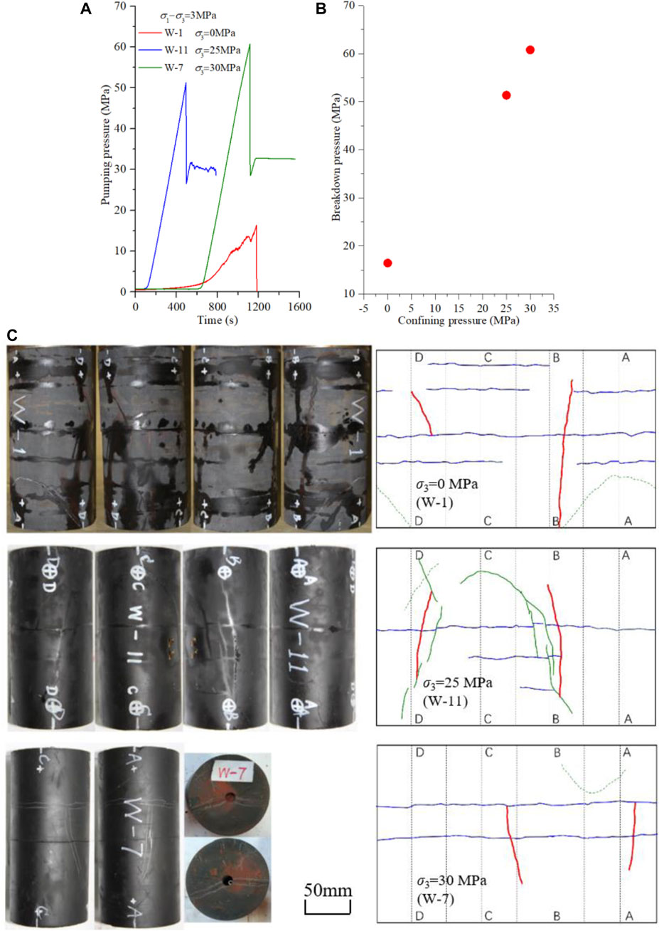
FIGURE 5. Pumping pressure curves and fracture morphologies at different confining pressures: (A) pumping pressure vs. time, (B) breakdown pressure vs. confining pressure, and (C) photographed and depicted surface distributions of hydraulic fractures.
Regarding fracture morphology, the amount and complexity of hydraulic fractures shows a declining trend with increasing confining pressure (Figure 5C). At a confining pressure of 25 MPa, specimen W-11 is well developed with cemented natural fractures. During the propagation of hydraulic fractures, these natural fractures are fully activated and connected. The interconnected hydraulic–bedding–natural fracture network is presented. In addition, it is worth noting that a sufficient opening of the bedding structure could be seen under all three conditions. Therefore, it could be inferred that confining pressure would not remarkably restrain the cracking of bedding planes.
The pumping rate is one of the few controllable parameters in hydraulic fracturing. A large pumping rate could produce a high net pressure and promote the full extension of the hydraulic fractures into the formation. As the pumping rate increases from 0.01 ml/s to 0.04 ml/s, the breakdown pressure increases from 51.40 to 61.78 MPa (Figures 6A,B). The pressurizing rate (slope of the linear part of the pressure‒time curve) also increases almost linearly (Figure 6C).
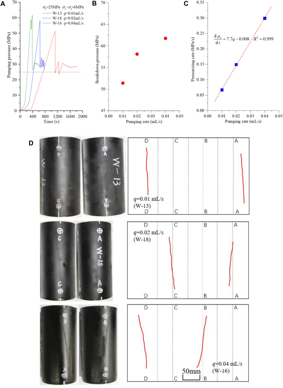
FIGURE 6. Pumping pressure curves and fracture morphologies at different pumping rates: (A) pumping pressure vs. time, (B) breakdown pressure vs. pumping rate, (C) pressurizing rate vs. pumping rate, and (D) photographed and depicted surface distributions of hydraulic fractures.
As photographed and depicted in Figure 6D, only double-wing hydraulic fractures are formed in all specimens. At a pumping rate of 0.01 ml/s, the trace of hydraulic fractures is subtle and not easy to observe with the naked eye. When the pumping rate increases to 0.04 ml/s, the fracture width becomes obvious. No bedding fractures are observed under any of the three conditions, which might be attributed to two aspects. One is the relatively large deviatoric stress (6 MPa), and the other is the locally undeveloped bedding structure.
Slick water and guar gum are two major injection fluids widely and heavily used in shale gas hydraulic fracturing. Slick water has low viscosity (usually below 10 mPa s) and can penetrate into tiny fractures, which is conducive to the formation of complex fractures. In contrast, guar gum bears high viscosity (101∼102 mPa s), and its main duty is producing wide main fractures.
As shown in Figure 7A, pumping guar gum brings about a higher breakdown pressure than injecting slick water. Specifically, the peak value grows from 51.36 to 57.40 MPa, increasing by 11.8%. The fracture morphology also exhibits significant differences. The specimen, fractured by slick water, has not only the main hydraulic fractures, but also activated bedding and natural fractures. The final fracture morphology is relatively complex (Figure 7B). For the specimen stimulated by guar gum, only the main hydraulic fractures were formed, and the fracture geometry was very simple.
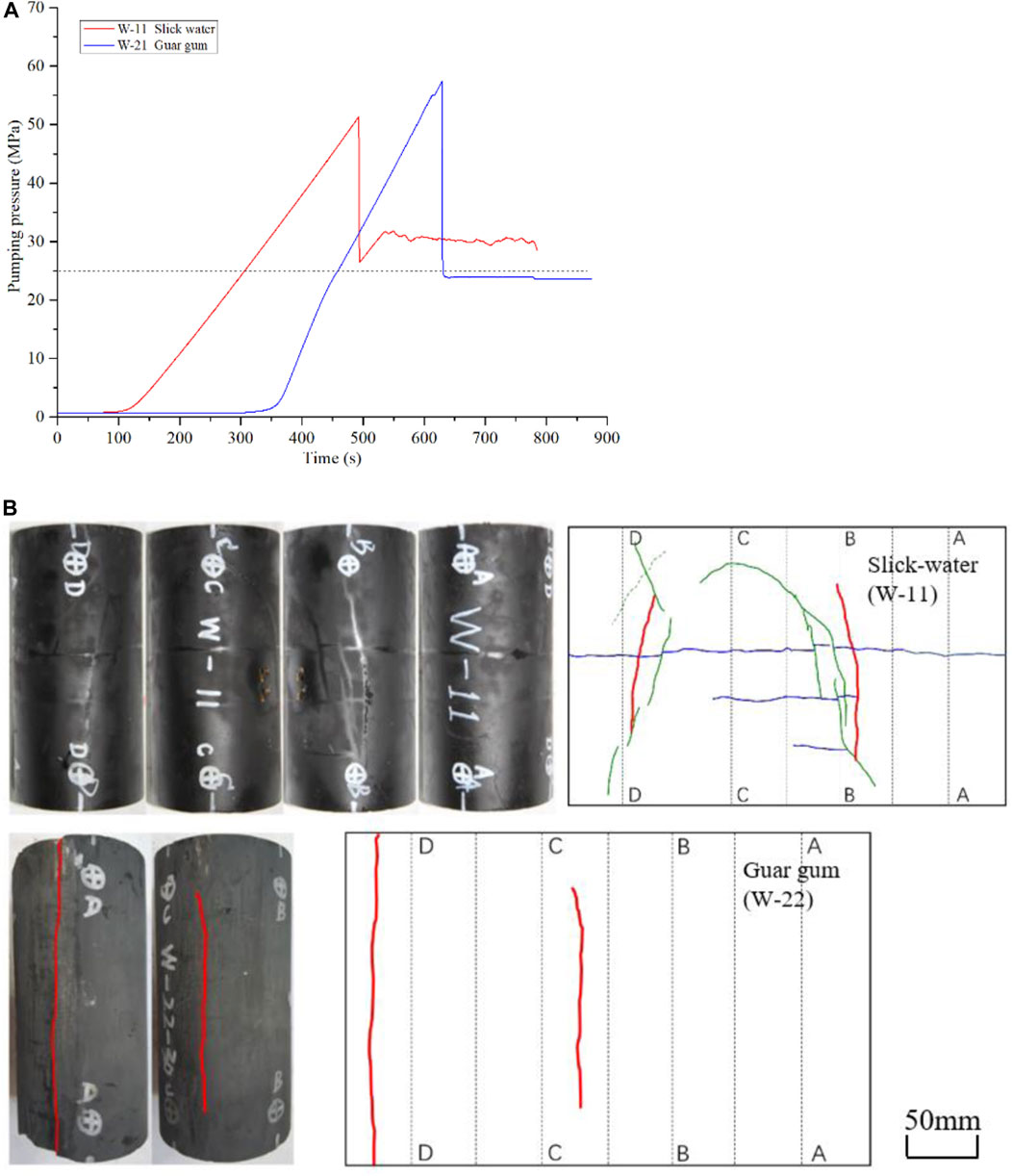
FIGURE 7. Pumping pressure curves and fracture morphologies at different fracturing fluid types: (A) pumping pressure vs. time, and (B) photographed and depicted surface distributions of hydraulic fractures.
Shale has a special bedding structure. The well trajectory is not always strictly vertical or horizontal to the bedding. As portrayed in Figure 8, with an increasing bedding angle, the breakdown pressure ascends after an initial declining trend. The minimum value is taken at a bedding angle of 30°. The curve shape of the pumping pressure vs time at β= 30° is also special, and does not exhibit significant post-peak drop features. The reason might be that the initial hydraulic fractures quickly communicate with weak bedding or/and natural fractures.
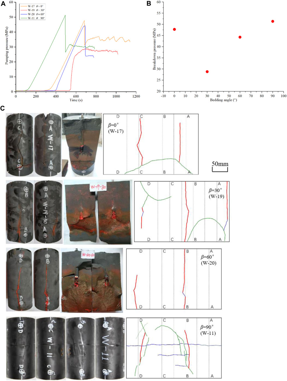
FIGURE 8. Pumping pressure curves and fracture morphology at different bedding angles: (A) pumping pressure vs. time, (B) breakdown pressure vs. bedding angle, and (C) photographed and depicted surface distributions of hydraulic fractures.
The fracture morphology is also remarkably influenced by the bedding angle. For specimen W-17, at a bedding angle of 0° (Figure 8C), the drilling hole is coplanar with the bedding plane. Hydraulic cracks initiate from the open hole section and propagate along the bedding structure. In addition, a natural fracture is activated and opened. When the bedding angle is set to 30°, the propagation of the hydraulic fractures is still affected by the bedding structure. A main hydraulic fracture first initiates and propagates. Then, it reorients to the inclined bedding plane. The extended bedding fracture further activates a natural fracture. The final interconnected hydraulic–bedding–natural fractures are formed. At a bedding angle of 60°, the fracture morphology is relatively simple, but the bedding structure also participates in the formation of hydraulic fractures. A main hydraulic fracture is divided into two parts by a short path of bedding fracture, implying that the fracture has temporarily changed its direction to a bedding plane. At a bedding angle of 90°, the main hydraulic cracks pass through the bedding and continue to propagate along their previous vertical direction. However, they are finally arrested by natural fractures with a relatively small approaching angle.
The data of the breakdown pressures and various fracture lengths for all specimens can be found in Supplementary Table A2.
Based on the description of fracture geometry in Section 3.2.1–3.2.5, specimen W-11 is selected to implement CT scanning for its relatively complex fracture morphology (containing an interconnected hydraulic–bedding–natural fracture network).
As shown in Figure 9, three slice images of CT scanning are presented. In Figure 9A, the slice image is perpendicular to the axis of the borehole and in the open hole section. The main hydraulic fractures initiate from two opposite positions at the borehole wall and propagate to the boundary of the cylinder. The measured widths of the two hydraulic fractures are distributed in 155.4–211.3 μm (mean value 177.0 μm) and 143.7–185.4 μm (mean value 170.6 μm). This minor difference in the fracture width indicates a balanced extension in both directions. Another finding is that the crack width decreases as the fracture gradually moves away from the borehole.
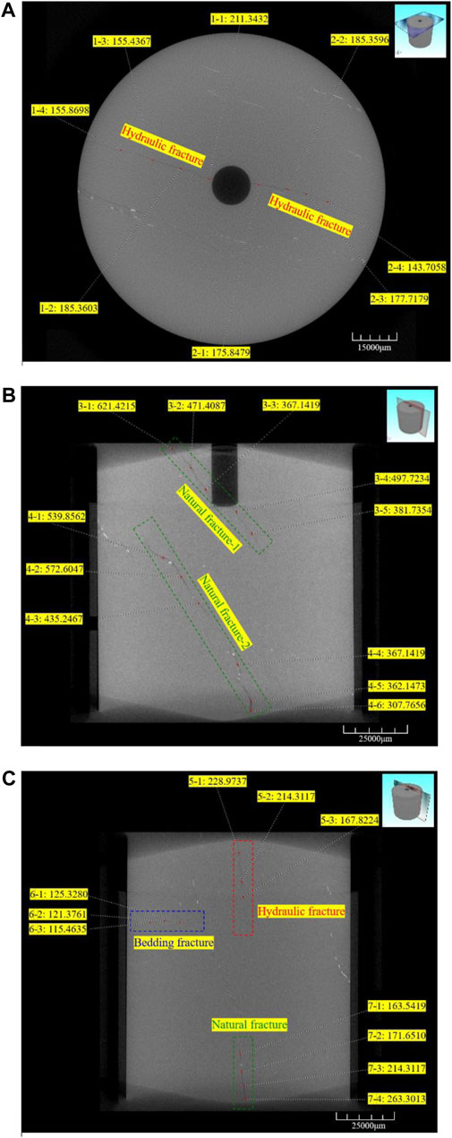
FIGURE 9. CT scanning images and fracture width measurement for specimen W-11: (A) slice image perpendicular to the axis of the borehole, (B) slice along the axis of the borehole, and (C) slice image parallel to the axis of the borehole with a certain offset.
In Figure 9B, the slice is along the axis of the borehole. Two natural fractures are recognized and measured. The first natural fracture is adjacent to the open hole section, and the values of the measured width vary largely between 367.1 and 621.4 μm, with an average value of 467.9 μm. The second fracture is in the lower part of the specimen. Its measured fracture width is 307.8–572.6 μm (mean value 430.8 μm). In Figure 9C, the slice image is parallel to the axis of the borehole with a certain offset. Three types of fractures (hydraulic, bedding, and natural fractures) are presented together. Hydraulic fracture 5 is vertical, and the average value of the fracture width is 203.7 μm. The opened bedding plane 6 is horizontal, with a mean width of 120.7 μm. Natural fracture 7 is gently oblique and has an average width of 203.2 μm. Different from the inclined natural fractures 3 and 4, natural fracture 7 extends nearly in the vertical direction. This implies that the formation mechanism of fracture 7 is tensile dominated, and the corresponding fracture width would be smaller, compared with shear-dominated fractures 3 and 4. Based on the aforementioned fracture classification and width measurement, the fracture width sorting is natural fracture > hydraulic fracture > bedding fracture. Natural fractures usually originate from tectonic shear failure. The mutual dislocation of fracture surfaces maintains a relatively large fracture width, even under compressive stress. The main hydraulic fracture is a kind of tension crack, which could gain a relatively better closure. The opened bedding is activated by hydraulic fractures. Because of the compression of overburden stress and low internal pressure, its width is the minimum among the three. The data of the measured fracture width from the CT images are listed in Supplementary Table A3.
The breakdown pressures under the five influencing factors are shown in Figure 10A. The variation ranges induced by each factor are different. Superficially, the alteration of confining pressure could bring about a substantial change in the breakdown pressure. The effect of deviatoric stress and bedding angle ranks second. The pumping rate and fracturing fluid type are in the last place. However, one thing worth noting is that these five influencing factors are not in unit consistency. Therefore, the aforementioned inference might not be correct, and parameter sensitivity analysis is needed.
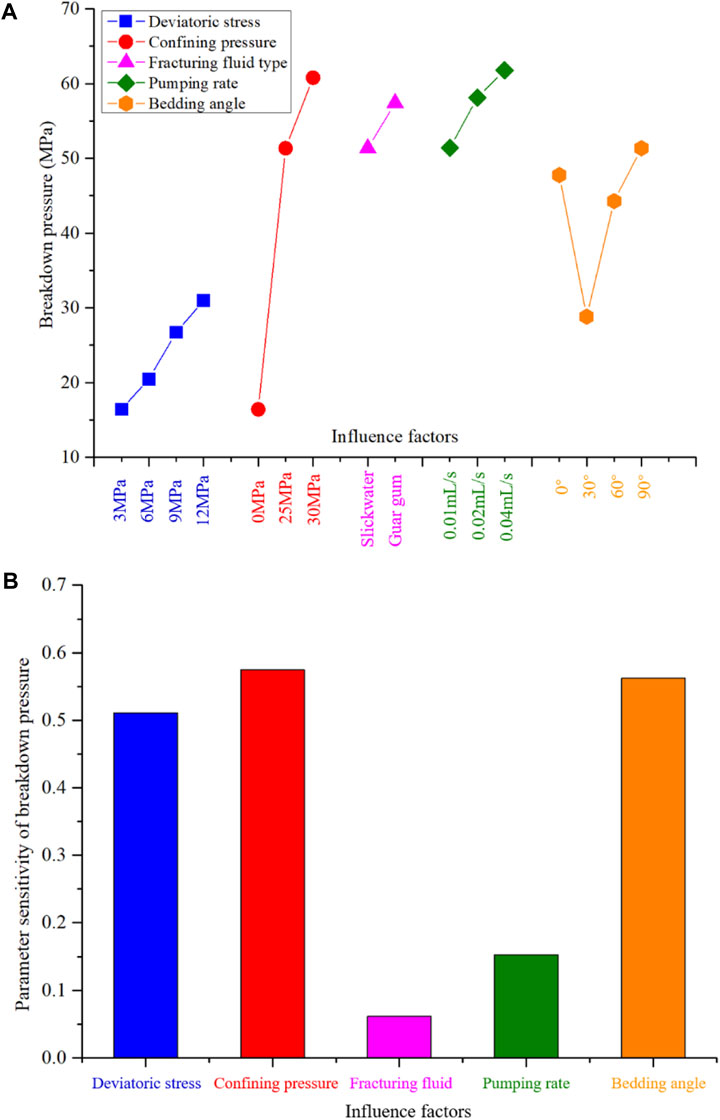
FIGURE 10. Breakdown pressures under various influence factors: (A) comparison of absolute values and (B) parameter sensitivity analysis.
Here, the relative change rate is applied to evaluate the parameter sensitivity of the breakdown pressure. The sensitivity index is expressed by:
where Si is the breakdown pressure sensitivity index of parameter i; Kimax is the maximum value of breakdown pressure in parameter i; Kimin is the minimum value of breakdown pressure in parameter i; Ximax is the maximum value of parameter i; Ximin is the minimum value of parameter i; and i represents the five influencing factors: deviatoric stress, confining pressure, pumping rate, fracturing fluid type, and bedding angle.
By calculating the sensitivity index of each factor, we drew Figure 10B. It should be noted that viscosity was used to quantify the influence of slick water (5 mPa s) and guar gum (100 mPa s) in the sensitivity analysis. The sequence of factors that influence the variation range of the breakdown pressure is confining pressure, bedding angle, deviatoric stress, pumping rate, and fracturing fluid type. The sensitivity of confining pressure, bedding angle, and deviatoric stress is much greater than that of pumping rate and the fracturing fluid type. Confining pressure, bedding angle, and deviatoric stress should be classified as geological factors, which are inherent and usually uncontrollable. The pumping rate and fracturing fluid type are engineering factors that can be regulated and controlled. This demonstrates that geological factors would largely determine the breakdown pressure and engineering factors could only affect it to a lesser extent.
The fracture length of each specimen is measured and recorded, according to the different fracture types. As shown in Figure 11, without considering the contribution of natural and bedding fractures, the length of the hydraulic fractures is only approximately 60–210 mm (average value 150 mm). In comparison, if the natural and/or bedding fracture could be fully activated under certain conditions, the total fracture length could increase up to 4 times and reach approximately 600 mm, greatly improving the fracture complexity and stimulated volume. Factors, such as low deviatoric stress, low confining pressure, low viscous slick water, and high bedding angle are conducive to activating natural and bedding fractures and forming a complex fracture network.
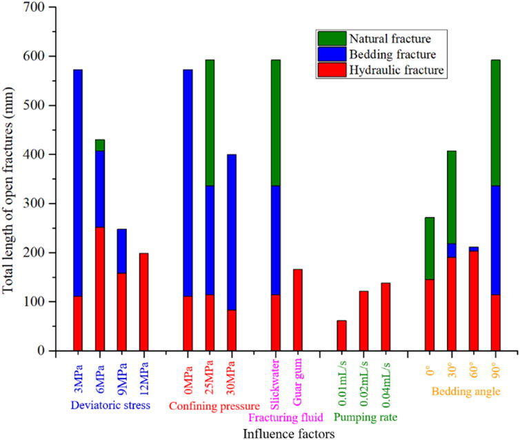
FIGURE 11. The total length of open fractures under various influence factors.
Owing to the irregular development of natural fractures, the cylindrical specimens exhibit certain heterogeneity, which could inevitably affect the comparative analyses of the results. We tried to minimize the influence of heterogeneity from sample preparation to result analysis. During outcrop sampling, we selected shale blocks with relatively few natural fractures. Before hydraulic fracturing, a small value of pressure (0.5-1 MPa) is held to check the tightness and integrity of the specimen. In this way, we could guarantee that the rock in the vicinity of the open hole is in a relatively intact state for all specimens. The initiation of hydraulic fractures can be regarded as being in a comparable state. The sharp pressure decline after the peak value demonstrates the initial intact state around the open hole. Therefore, the test values of the breakdown pressures are little affected by the heterogeneity. During the propagation of hydraulic fractures, natural fractures affect the final morphology of the hydraulic fractures. The influence of natural fractures was depicted and quantitatively analyzed.
By considering the major geological and engineering factors, laboratory hydraulic fracturing experiments are implemented. Statistical analyses of breakdown pressure, fracture morphology, and parameter sensitivity are conducted. The conclusions are as follows:
1) The increase in deviatoric stress could significantly improve breakdown pressure and observably hinder the cracking of bedding planes, reducing the complexity of the hydraulic fracture morphology.
2) The width of the activated natural fractures (approximately 430 μm) is much greater than that of hydraulic fractures (170 μm) and opened bedding planes (120 μm), implying that the mutual dislocation of shear fracture surfaces could maintain a relatively large fracture width than the crack created by the tension mechanism.
3) By using the sensitivity analysis, the sequence of factors that influence the variation range of breakdown pressures is confining pressure, bedding angle, deviatoric stress, pumping rate, and fracturing fluid type. Geological factors would largely determine the breakdown pressure, while engineering factors could only affect it to a lesser extent.
4) The length of the pure hydraulic fracture is quite limited. Low deviatoric stress, low confining pressure, low viscous slick water, and a high bedding angle are conducive to activating natural and bedding fractures and forming a complex fracture network.
The original contributions presented in the study are included in the article/Supplementary Material; further inquiries can be directed to the corresponding author.
LW and JZ contributed to the conception and design of the study. JZ performed the statistical analysis. LW wrote the draft of the manuscript. XS and WG wrote sections of the manuscript. YG was responsible for review and editing. All authors contributed to manuscript revision, read, and approved the submitted version.
This work was sponsored by the ‘‘National Natural Science Foundation of China’’ (No. 52104010, No. 12002351), and Youth Innovation Promotion Association CAS (No. 2021286).
JZ was employed by the company CNOOC Research Institute Co., Ltd.
The remaining authors declare that the research was conducted in the absence of any commercial or financial relationships that could be construed as a potential conflict of interest.
All claims expressed in this article are solely those of the authors and do not necessarily represent those of their affiliated organizations, or those of the publisher, the editors, and the reviewers. Any product that may be evaluated in this article, or claim that may be made by its manufacturer, is not guaranteed or endorsed by the publisher.
The Supplementary Material for this article can be found online at: https://www.frontiersin.org/articles/10.3389/feart.2022.952655/full#supplementary-material
σ1 Axial stress, MPa; σ3 Confining pressure, MPa; σ1-σ3 Deviatoric stress, MPa; σV Vertical stress, MPa; σH Maximum horizontal principal stress, MPa; σh Minimum horizontal principal stress, MPa; pb Breakdown pressure, MPa; t Injection time, s; q Pumping rate, mL/s; β Bedding angle, °; L Fracture length, mm. Si Breakdown pressure sensitivity index of parameter i. Kimax The maximum value of breakdown pressure in parameter i. Kimin The minimum value of breakdown pressure in parameter i. Ximax The maximum value of parameter i. Ximin The minimum value of parameter i.
Cai, C., Kang, Y., Yang, Y., Wang, X., Li, Y., Huang, M., et al. (2020). The effect of shale bedding on supercritical CO2 jet fracturing: A experimental study. J. Pet. Sci. Eng. 195, 107798. doi:10.1016/j.petrol.2020.107798
Crosby, D. G., Rahman, M. M., Rahman, M. K., and Rahman, S. S. (2002). Single and multiple transverse fracture initiation from horizontal wells. J. Pet. Sci. Eng. 35, 191–204. doi:10.1016/S0920-4105(02)00243-7
De Pater, C. J., Cleary, M. P., Quinn, T. S., Barr, D. T., Johnson, D. E., and Weijers, L. (1994). Experimental verification of dimensional analysis for hydraulic fracturing. SPE Prod. Facil. 9, 230–238. doi:10.2118/24994-pa
Fisher, M. K., Heinze, J. R., Harris, C. D., Davidson, B. M., Wright, C. A., and Dunn, K. P. (2004). Optimizing horizontal completion techniques in the barnett shale using microseismic fracture mappina. Proc. - SPE Annu. Tech. Conf. Exhib., 1099–1109. doi:10.2523/90051-ms
Guo, T., Zhang, S., Qu, Z., Zhou, T., Xiao, Y., and Gao, J. (2014). Experimental study of hydraulic fracturing for shale by stimulated reservoir volume. Fuel 128, 373–380. doi:10.1016/j.fuel.2014.03.029
Guo, Y., Hou, L., Yao, Y., Zuo, L., Wu, Z., and Wang, L. (2020). Experimental study on influencing factors of fracture propagation in fractured carbonate rocks. J. Struct. Geol. 131, 103955. doi:10.1016/j.jsg.2019.103955
He, J., Li, X., Yin, C., Zhang, Y., and Lin, C. (2020). Propagation and characterization of the micro cracks induced by hydraulic fracturing in shale. Energy 191, 116449. doi:10.1016/j.energy.2019.116449
Hou, B., Chang, Z., Fu, W., Muhadasi, Y., and Chen, M. (2019). Fracture initiation and propagation in a deep shale gas reservoir subject to an alternating-fluid-injection hydraulic-fracturing treatment. SPE J. 24, 1839–1855. doi:10.2118/195571-PA
Hou, B., Chen, M., Li, Z., Wang, Y., and Diao, C. (2014). Propagation area evaluation of hydraulic fracture networks in shale gas reservoirs. Petroleum Explor. Dev. 41, 833–838. doi:10.1016/S1876-3804(14)60101-4
Hou, B., Zhang, R., Zeng, Y., Fu, W., Muhadasi, Y., and Chen, M. (2018). Analysis of hydraulic fracture initiation and propagation in deep shale formation with high horizontal stress difference. J. Pet. Sci. Eng. 170, 231–243. doi:10.1016/j.petrol.2018.06.060
Jarvie, D. M., Hill, R. J., Ruble, T. E., and Pollastro, R. M. (2007). Unconventional shale-gas systems: The Mississippian Barnett Shale of north-central Texas as one model for thermogenic shale-gas assessment. Am. Assoc. Pet. Geol. Bull. 91, 475–499. doi:10.1306/12190606068
Jin, X., Shah, S. N., Roegiers, J. C., and Zhang, B. (2015). An integrated petrophysics and geomechanics approach for fracability evaluation in shale reservoirs. SPE J. 20, 518–526. doi:10.2118/168589-PA
Li, S., Liu, L., Chai, P., Li, X., He, J., Zhang, Z., et al. (2019). Imaging hydraulic fractures of shale cores using combined positron emission tomography and computed tomography (PET-CT) imaging technique. J. Pet. Sci. Eng. 182, 106283. doi:10.1016/j.petrol.2019.106283
Ma, Y., Cai, X., and Zhao, P. (2018). China’s shale gas exploration and development: Understanding and practice. Petroleum Explor. Dev. 45, 589–603. doi:10.1016/S1876-3804(18)30065-X
Mayerhofer, M. J., Lolon, E. P., Rightmire, C., Walser, D., Cipolla, C. L., and Warplnskl, N. R. (2010). What is stimulated reservoir volume? SPE Prod. Oper. 25, 89–98. doi:10.2118/119890-PA
Rahimzadeh Kivi, I., Ameri, M., and Molladavoodi, H. (2018). Shale brittleness evaluation based on energy balance analysis of stress-strain curves. J. Pet. Sci. Eng. 167, 1–19. doi:10.1016/j.petrol.2018.03.061
Song, X., Guo, Y., Zhang, J., Sun, N., Shen, G., Chang, X., et al. (2019). Fracturing with carbon dioxide: From microscopic mechanism to reservoir application. Joule 3, 1913–1926. doi:10.1016/j.joule.2019.05.004
Tan, P., Jin, Y., Han, K., Hou, B., Guo, X., Gao, J., et al. (2017). Analysis of hydraulic fracture initiation and vertical propagation behavior in laminated shale formation. Fuel 206, 482–493. doi:10.1016/j.fuel.2017.05.033
Wang, L., Guo, Y., Yang, C., Xiao, J., Lu, C., and Song, Y. (2020). Mechanical characterization of continental shale in Sichuan Basin of China and its potential impact on reservoir stimulation. J. Nat. Gas. Sci. Eng. 79, 103346. doi:10.1016/j.jngse.2020.103346
Xu, Y., Lei, Q., Chen, M., Wu, Q., Yang, N., Weng, D., et al. (2018). Progress and development of volume stimulation techniques. Petroleum Explor. Dev. 45, 932–947. doi:10.1016/S1876-3804(18)30097-1
Yang, H., Guo, Y., Wang, L., Bi, Z., Guo, W., Zhao, G., et al. (2022). Study on the Stimulation Effectiveness Evaluation of Large- Scale Hydraulic Fracturing Simulation Experiment Based on Optical Scanning Technology, 1–19.
Zhang, J., Shi, M., Wang, D., Tong, Z., Hou, X., Niu, J., et al. (2021). Fields and directions for shale gas exploration in China. Nat. Gas. Ind. 41, 69–80. doi:10.3787/j.issn.1000-0976.2021.08.007
Zhang, X., Lu, Y., Tang, J., Zhou, Z., and Liao, Y. (2017). Experimental study on fracture initiation and propagation in shale using supercritical carbon dioxide fracturing. Fuel 190, 370–378. doi:10.1016/j.fuel.2016.10.120
Zhang, Y., He, J., Li, X., and Lin, C. (2019). Experimental study on the supercritical CO2 fracturing of shale considering anisotropic effects. J. Pet. Sci. Eng. 173, 932–940. doi:10.1016/j.petrol.2018.10.092
Zhou, Z. Le, Zhang, G. Q., Dong, H. R., Liu, Z. Bin, and Nie, Y. X. (2017). Creating a network of hydraulic fractures by cyclic pumping. Int. J. Rock Mech. Min. Sci. 97 (1997), 52–63. doi:10.1016/j.ijrmms.2017.06.009
Zhou, Z. Le, Zhang, G. Q., Xing, Y. K., Fan, Z. Y., Zhang, X., and Kasperczyk, D. (2019). A laboratory study of multiple fracture initiation from perforation clusters by cyclic pumping. Rock Mech. Rock Eng. 52, 827–840. doi:10.1007/s00603-018-1636-5
Zou, C., Ding, Y., Lu, Y., Liu, X., Chen, J., Wang, X., et al. (2017). Concept, technology and practice of “man-made reservoirs” development. Petroleum Explor. Dev. 44, 146–158. doi:10.1016/S1876-3804(17)30019-8
Keywords: hydraulic fracturing, marine shale, breakdown pressure, fracture morphology, sensitivity analysis, influencing factor
Citation: Wang L, Zhou J, Guo Y, Song X and Guo W (2022) Laboratory investigation and evaluation of the hydraulic fracturing of marine shale considering multiple geological and engineering factors. Front. Earth Sci. 10:952655. doi: 10.3389/feart.2022.952655
Received: 25 May 2022; Accepted: 01 August 2022;
Published: 26 August 2022.
Edited by:
Jingshou Liu, China University of Geosciences Wuhan, ChinaReviewed by:
Shuai Heng, Henan Polytechnic University, ChinaCopyright © 2022 Wang, Zhou, Guo, Song and Guo. This is an open-access article distributed under the terms of the Creative Commons Attribution License (CC BY). The use, distribution or reproduction in other forums is permitted, provided the original author(s) and the copyright owner(s) are credited and that the original publication in this journal is cited, in accordance with accepted academic practice. No use, distribution or reproduction is permitted which does not comply with these terms.
*Correspondence: Lei Wang, bHdhbmdAd2hyc20uYWMuY24=
Disclaimer: All claims expressed in this article are solely those of the authors and do not necessarily represent those of their affiliated organizations, or those of the publisher, the editors and the reviewers. Any product that may be evaluated in this article or claim that may be made by its manufacturer is not guaranteed or endorsed by the publisher.
Research integrity at Frontiers
Learn more about the work of our research integrity team to safeguard the quality of each article we publish.