 Chen Zhang1
 Junpeng Zou
94% of researchers rate our articles as excellent or good
Learn more about the work of our research integrity team to safeguard the quality of each article we publish.
Find out more
ORIGINAL RESEARCH article
Front. Earth Sci., 22 June 2022
Sec. Geohazards and Georisks
Volume 10 - 2022 | https://doi.org/10.3389/feart.2022.933192
This article is part of the Research TopicGeological Disasters in Deep Engineering Mechanism, Warning and Risk mitigationView all 39 articles
In the mining process of deep coal mines with a thick and hard roof, it is easy to form a large overhanging roof and accumulate a lot of strain energy. The sudden breaking of the suspended roof may induce seisms, which seriously threaten the safety of underground miners and equipment. To reveal the mechanism of weakening the thick and hard roof by blasting in deep mining, the four times deep-hole blasting in 63upper06 panel of Dongtan coal mine are considered. First, the temporal and spatial distribution of seismicity events monitored before and after blasting is investigated. Second, the process of deep-hole blasting is simulated using finite element and discrete element methods. After blasting, the small-energy mining-induced seismicities within 20 m of the roof suddenly increase and gradually transfer to the mined-out area and the front of the working face. Meanwhile, the high rock stratum is broken and a large amount of strain energy is released, which causes the range of fall zone enlarge a lot, and the stress in the roof is decreased obviously. With the increase in the number of deep-hole blasting, the pressure relief effect becomes more obvious, and the newly developed fracture is mainly located in the low strata. Microseismic monitoring results agree with the calculated results. Moreover, the rock caving steps are easily formed after deep-hole blasting, and the collapse is more sufficient. Furthermore, blasting cracks are most restrained in the vertical direction of the maximum principal stress. Moreover, the delayed blasting method is more conducive to the expansion and penetration of blasting cracks. Results show that the deep-hole blasting technology has a significant effect on weakening the roof of coal seam and preventing and controlling large-energy mining-induced seismicities.
Coal is an important fossil energy. With the decrease of shallow coal resources, coal mining gradually shifts to the deep. Due to the deep mining environment with high stress (He et al., 2015), the rock will have the characteristics of good integrity and high strength, and then thick and hard roofs will be formed at the top of the coal seam. Therefore, long cantilevers will be formed during mining, resulting in rock burst (Senfaute and Chambo, 1997), mine seismicities (Gibowicz and Lasocki, 2001), land subsidence (Zhang, et al., 2022), and other hazards. At present, the main methods to prevent and control these disasters include the hydraulic fracturing method (Huang et al., 2015), the deep-hole blasting method, and so on. The deep-hole blasting method is used to weaken the thick and hard roof in the sixth mining area of Dongtan Coal Mine in Yanzhou, Shandong Province, China, and a good governance effect was obtained. Thus, combined with the actual engineering background, this work studies the mechanism of deep-hole blasting to weaken the thick and hard roof to prevent mine seismicities disasters.
The weakening mechanism of rock blasting is still an ongoing topic. The generally accepted theory is that after rock blasting, the instantaneous reflection and tensile effect of explosive stress wave and the gas wedge effect of detonation gas increase the radius of the blast hole cavity, and generate a crushing zone and a fracture zone, thereby reducing the strength of rock (Kutter and Fairhurst, 1971; Xie et al., 2017) Due to the large horizontal ground stress in deep coal mining, the elastic stage, plastic strain stage, and damage softening stage of rock failure are different from those of shallow rock. Researchers proposed a failure surface equation for concrete under large strain, high strain rate, and high pressure (Holmquist et al., 1993). On this basis, the RHT constitutive model is proposed (Riedel, 2004), which provides the possibility for the damage calculation of rock after blasting in a deep high-stress environment. Meanwhile, deep-hole blasting is equivalent to a black box, and how the rock damage and cracks in the roof evolve in the high-stress environment cannot be directly observed. So, the method of numerical simulation has become an important research way. The RHT constitutive model is embedded into the finite element software AUTODYN, and the research on the parameter setting of the RHT constitutive model has made great progress in the study of rock blasting weakening. It systematically analyzes the rock breaking process in borehole blasting and puts forward the ' dynamic and static pressure ' breaking principle of rock borehole blasting (Century Dynamics Ltd., 2000). More numerical models of borehole blasting began to be simulated by AUTODYN software, such as rock breaking process of single-hole and double-hole blasting, borehole non-coupling charge blasting, etc. (Chun et al., 2009). With the development of finite element software, the RHT constitutive model is applied to the penetration experiment of LS-DYNA, and better damage and fracture evolution are obtained. It is found that the blasting effect of triangle hole arrangement is better than that of traditional straight hole arrangement (Zuo et al., 2019). For this reason, this study establishes a triangular hole model by the LS-DYNA finite element software based on the RHT constitutive model to explore the damage evolution law of rock under high confining pressure.
In terms of the mechanism of induced mine seismicities in coal mining with the thick and hard roof, the initial caving interval of roof collapse above the coal seam is large, and the rotation and subsidence of the suspended roof will produce higher lateral support pressure above the working face, which is the main source of strong activity of rock strata above the working face (Chen and Liu, 2018). According to the research, the mine seismicities are prone to occur at the first square. The mechanism of rock movement and instability in the coal mine is studied when there are multi-layer thick and hard rock layers above the coal seam. The analysis shows that the early mine seismicities occur frequently in the low rock layer and the released energy is small, in the form of rotating sliding. With the advancement of the working face, it gradually shifts to the high strata. Shear slip often occurs in high strata, which leads to large-energy mine seismicities. A large mine seismicity will be caused by the synergistic rupture of multi-layer hard rock (He et al., 2015; Jiao et al., 2021). After rock fracture, the contact behavior is controlled by the asperity when the working face is disturbed again by the external force. The researchers compared and analyzed the application effect of two roughness peak recognition and evaluation methods in the three-dimensional field (Tang et al., 2022), which provides a worthy reference method for conducting laboratory experiments to study the mechanism of mineral seismicities generated by the remotion of fractured rocks due to the transport of overlying rocks.
In terms of the mechanism of weakening the thick and hard roof by deep-hole blasting, the blasting pressure relief technology was first used in the mining of metal mines in South Africa and achieved a good pressure relief effect (Guest et al., 1995). The monitoring results of the working resistance of the hydraulic support show that the deep-hole blasting technology can effectively shorten the periodic weighting step and reduce the variation range of the stress redistribution of the weathered rock. The mechanism of weakening the thick and hard roof is mainly reflected in the two aspects of static load reduction and dynamic load response (Lu et al., 2021). In the study of blast hole parameters, it is found by numerical simulation that when the aperture is constant, with the increase of the hole depth, the stress time of the unit at the same position is gradually extended, and the cracks in the coal seam are easier to expand, that is, the deeper the borehole is, the better the effect of weakening the thick and hard roof is (Liu et al., 2012). Finally, there are some studies on the evaluation of the blasting effect. Using the microseismic monitoring method, it is found that the microseismic waveform information induced by pressure relief blasting can describe the release process of blasting stress and mining stress, so the blasting efficiency index to evaluate the pressure relief effect can be proposed to better guide the actual production (Kan et al., 2022).
The existing research has made many in-depth discussions on the prevention and control of rock burst and mine seismicities disasters by blasting weakening the thick and hard roof in terms of theoretical analysis. However, the numerical analysis of practical engineering is mainly based on the observation of micro-hole cracks, which is lack macroscopic simulation of the whole mining process. It is unable to intuitively observe the migration and stress change of the hard roof after blasting. Based on the engineering background of the 63upper06 mining panel of Dongtan deep coal mine, this study statistically analyzethe spatial and temporal distribution of mine seismicities before and after multiple blasting. Moreover, the stress change in the hard strata above the coal seam is also studied. Both results are used to reveal the mechanism of blasting weakening the thick and hard roof to prevent mine seismicities.
The 63upper06 panel is located in the No.6 mining area of the Dongtan coal mine (see Figure 1). The coal seam in this mining area is gently undulating, and the dip angle of the coal seam is 0°∼14°, with an average of about 4°. The strata in the mining area generally have a large dip angle in the west, and gentle in the east. The main stratigraphic physical and mechanical parameters of the studied panel roof are listed in Table 1.
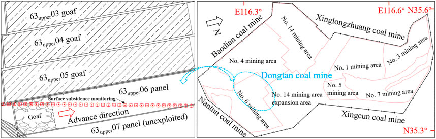
FIGURE 1. Distribution of mining areas in Dongtan coal mine and panels in No. 6 mining area.
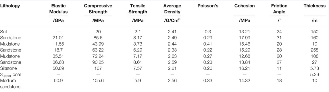
TABLE 1. Main physical and mechanical parameters of the strata in No. 6 mining area.
A total of 1927 seisms occur in the 63upper06 panel of Dongtan coal mine from March 2020 to the first deep-hole blasting on March 9, 2021 (see Figure 2). Among them, there are 26 large seisms with the energy of 105 J and above, and the largest energy is 6.81 × 10⁶ J (see Figure 3).
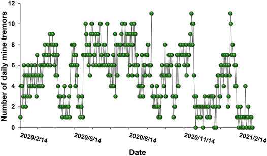
FIGURE 2. Distribution of the mining-induced seismicities on the 63upper06 panel before the treatment.
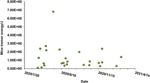
FIGURE 3. Strong mining-related seismicities (>105 J).
A total of four times deep-hole blasting are conducted at the 63upper06 panel in the Dongtan No.6 mining area. The first deep-hole blasting is carried out when the working face is advanced by 597 m, with a total of 12 holes arranged, each at a depth of 90 m, in a vertical direction, with a charge of 90 kg. When the working face is advanced 651 m, the second blasting is carried out, 17 holes are set and the sequence of detonation is adjusted. When the working face is advanced to 712 and 753 m, the 3rd and 4th blasting are implemented, and 16 holes are arranged with a depth of 90m, breaking the sandstone layer in the range of 50–90 m above the coal seam. The holes are inclined to the trackside with an inclination of 80°∼90° (see Figure 4).
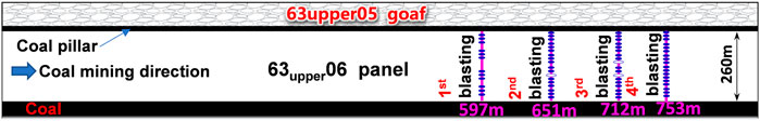
FIGURE 4. Schematic diagram of deep-hole blasting position.
The profile locations of mine-induced seismicities before and after blasting are shown in Figure 5, and the following analysis can be derived from the figure:
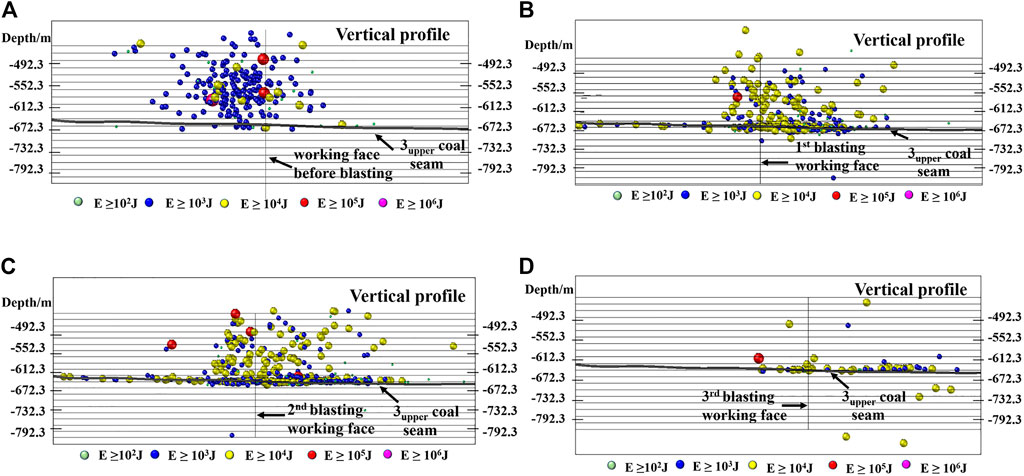
FIGURE 5. Profile distribution of mining-induced seismicities before and after deep-hole blasting: (A) distribution of mining-induced seismicities before blasting, (B) distribution of mining-induced seismicities after the first blasting at 597 m, (C) distribution of mining-induced seismicities after the second blasting at 651 m, and (D) distribution of mining-induced seismicities after the third blasting at 712 m.
Figure 5A shows that before blasting, the influence range of seismicity events is from 275 m in the goaf behind the working face to 80 m in front of the solid coal side. The seisms with large energy are mostly distributed in the range of 180–50 m in the goaf behind the working face, and the sections are 40 m, 60 m, and 140 m away from the coal seam roof on the profile, respectively.
Figure 5B shows that after the first blasting, the number of mining-induced seismicities in the 20 m range of coal seam roof and floor increased sharply, and the seisms are obviously transferred to the front of the working face. The influence range is from 116 m in the goaf behind the working face to 258 m in front of the solid coal side. The major mining-induced seismicities decrease and occur at 100 m in the goaf behind the working face and 80 m from the section to the coal seam roof on the profile. No mining-induced seismicities with energy greater than or equal to 106 J occur again.
Figure 5C shows that compared with the situation after the first blasting, the mining-induced seismicities and their energy increase significantly after the second blasting. The number of mining-induced seismicities continued to increase within the 20 m range of the roof and floor, a total of four major mining-induced seismicities occurred, and the magnitude of strong seisms energy is 105 J. The first major mine tremor occurs 63 m behind the working face and 200 m above the roof; the second occurs close to the working face, 157 m above the roof; the third large mine tremor occurs in the immediate roof of the coal seam and 140 m ahead of the working face; the fourth is 266 m behind the working face, 100 m above the coal seam. The influence range of mine earthquake after blasting is from 138 m behind the working face to 436 m in front of the solid coal side.
As shown in Figure 5D, after the third deep-hole blasting, the number of mining-induced seismicities decreases significantly, and the influence range is from 188 m behind the goaf to 470 m in front of the solid coal measurement. A major seism occurs 186 m behind the working face, 30 m above the coal seam.
According to the field monitoring data, the distribution of mining-induced seismicities before and after several deep-hole blastings can be concluded that after blasting, mining-induced seismicities may shift from the back of the working face to the front. The number of mining-induced seismicities within 20 m of the roof and floor of the coal seam increase significantly. Therefore, the average height of mine seismic events decreases, and the accumulated strain energy releases well. Compared with that before blasting, there has been a noticeable increase in the number of tremors with an energy of 104 J. However, the number of major mining-induced seismicities decreases, and those with energy that reaches 106 J basically disappear.
Different from the shallow coal seam, deep coal features higher in situ stresses. The different blasting methods also have a great influence on the evolution of rock damage cracks. The smaller the blasting hole spacing is, the more concentrated the effective stress action range generated by the blasting stress waves. Meanwhile, the energy decay rate will be slower, the rock crushing plastic zone and fracture zone will be extended to a larger extent, and the blasting effect will be better. Therefore, the triangular hole plane strain model with concentrated stress action is established, and it is simulated in the following three conditions:
I. Basic group model A. The rock mechanics parameters using 63upper06 panel high rock sandstone physical and mechanical parameters, no confining pressure, and five holes simultaneously detonated (see Figures 7A,B).
II. Control model B. Based on A, the X direction is applied with 20 MPa compressive stress, and the Z direction is applied with 5 MPa compressive stress. The impact of high in situ stresses on explosive crack growth could be investigated by comparing models A and B (see Figures 7C,D).
III. Control group model C. Model C is a case of delay blasting with two holes on the top left and bottom right with 1 ms delay initiation (see Figures 7E,F).
LS-DYNA finite element software is used to simulate the fluid-solid coupling of air and rock. The constitutive model of rock is the RHT model, and RHT constitutive equations are as Eq. 1, Eqs 6, 8. The parameters are listed in Table 2. The curve of RHT can be divided into three stages: elastic stage (equivalent stress

TABLE 2. RHT constitutive model parameters.
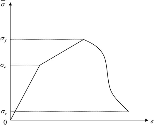
FIGURE 6. RHT constitutive model.
The failure stress
The strain rate factor is given as follows:
where
where
Under quasi-static loading conditions,
where
When
The elastic limit stress
where
The residual stress
where
The equation of state parameters of the explosive and air are listed in Table 3 and Table 4, equations of state for the explosive and air, as shown in Eqs 5, 6. The model size is 12 m (length) × 6 m (height), the accuracy is 0.001 m, and the vertical and horizontal spacings between adjacent boreholes are 2 m.
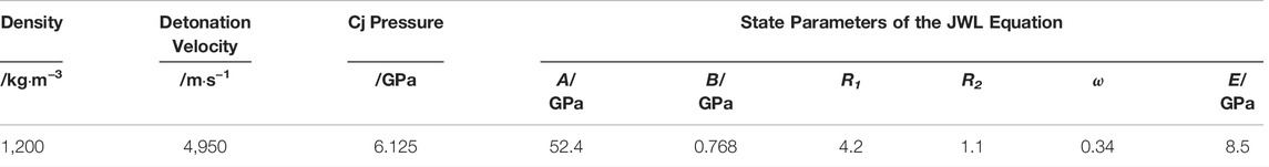
TABLE 3. Explosive material and its state equation parameters.
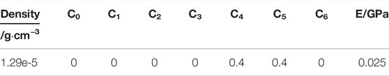
TABLE 4. Air material and its state equation parameters.
The equation of the explosive state is given as follows:
where
The equation of air state is given as follows:
where,
After the model A damage stops expanding, the radius of the smash district is 2–3 times of the aperture, the radius of the fracture zone is 11–17 times of the aperture, and the longest fracture radius is more than 2 m. After the damage of model B stops expanding, the radius of the smash district is 1–2 times of the aperture, the radius of the fracture zone is 10–13 times of the aperture, and the longest fracture is about 1.6 m. Figure 7D shows that the maximum principal stress has a great inhibitory effect on the crack propagation in the vertical direction. After the damage of model C stops expanding, the radius of the smash district is 2–3 times the pore diameter, the radius of the fracture zone is 11–20 times, and the longest fracture radius is 2.5 m. According to the crack propagation direction in the crack zones of No. 1 and No. 5 holes, the holes with cracks produced by blasting have an obvious orientation to the crack propagation of the unexploded holes, and the crack zone of the blast hole with delayed initiation becomes an ellipse with long axis pointing to the blast hole. The stress wave and detonation gas produced by delay initiation further activate the existing cracks, expand the crack area of the blast hole, and deepen the penetration of the blast hole spacing.
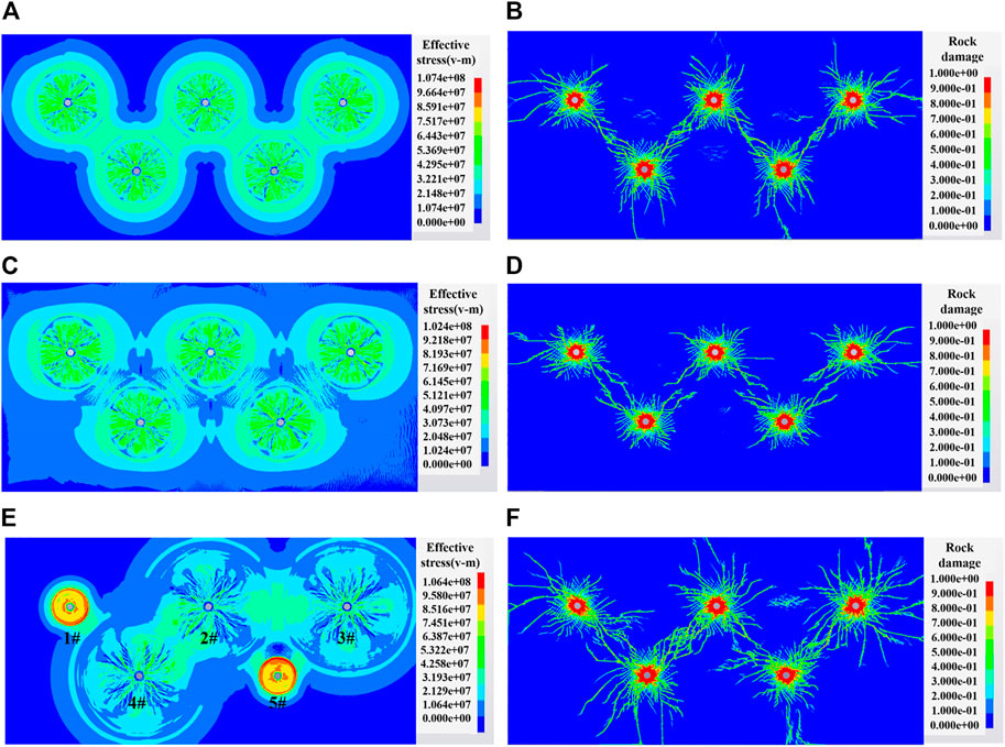
FIGURE 7. Stress and damage nephogram of rock blasting: (A) stress wave expansion nephogram of model A, (B) final damage nephogram of model A, (C) stress wave expansion nephogram of model B, (D) final damage nephogram of model B, (E) stress wave expansion nephogram of model C, and (F) final damage nephogram of model D.
According to the engineering geological conditions and the expansion law of burst cracks under the deep high stress conditions as described earlier, a discrete element model of the whole process of mining on the 63upper06 panel is established by UDEC software. The size of the model is 1,200 m (length) × 735 m (height), which limits the displacement of each node on both sides of the model and at the bottom (see Figure 8). The block element of rock and coal seam adopts the Mohr-Coulomb constitutive model, and the contact constitutive model of the elastic-plastic joint zone with Coulomb slip failure is adopted. The cracks after blasting are approximately simulated by horizontal and cross joints, with a length of 8–10 times the aperture. From right to left, 500 m of excavation is divided into five steps, and then four times deep-hole blasting is carried out. The blasting positions are all within the range of 10 m behind the working face. Finally, 50 m of excavation is continued to observe the subsequent stress distribution. The horizontal ground stress is applied to the model at 23 MPa. The physical and mechanical parameters in Table 1 are used for the stratigraphic parameters.
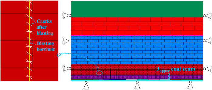
FIGURE 8. Excavation and the blast hole model.
Figure 9 shows the displacement and stress changes in the vertical profile after four simulated roof breaking. When the working face is advanced 597 m, the first blasting is carried out (see Figures 9A,B). The following three blastings are conducted when the working face is advanced at 651 (Figures 9C,D), 712 (Figures 9E,F), and 753 m (Figures 9G,H), respectively.
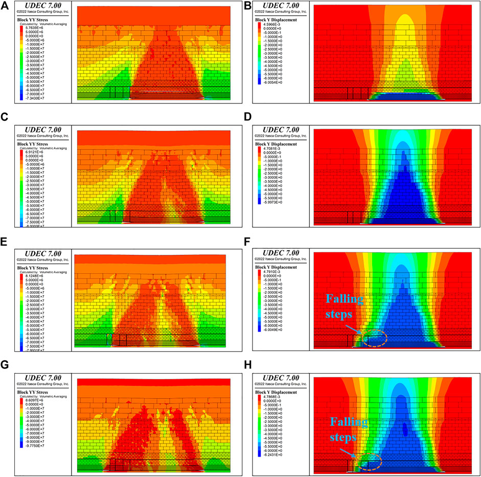
FIGURE 9. Stress and displacement nephograms of deep-hole blasting (+ represents the tensile stress, - represents compressive stress): (A) the stress nephogram after the 1st blasting; (B) the displacement nephogram after the 1st blasting; (C) the stress nephogram after the 2nd blasting; (D) the displacement nephogram after the 2nd blasting; (E) the stress nephogram after the 3rd blasting; (F) the displacement nephogram after the 3rd blasting; (G) the stress nephogram after the 4th blasting; and (H) the displacement nephogram after the 4th blasting.
After the first blasting, the suspended roof collapses rapidly. Within the range of 56 m above the coal seam and 80 m behind the working face, the roof weighting fracture and rotary instability failure occur in the low strata, which is easy to produce high-frequency and low-energy mining-induced seismicities. The range of tensile stress zone after roof cutting is expanded, and the stress concentration zone is formed within the range of 73–86 m above the roof near the end of the blasting hole. It is prone to mining-induced seismicities. Combined with the spatial and temporal distribution range of mining-induced seismicities in the mining area after blasting and the location of major mining-induced seismicities mentioned in Chapter 2, the results are close to the numerical simulation results, which verifies the feasibility of the model. Meanwhile, the suddenly forced roof caving causes the separation of the low rock layer from the upper mudstone layer and the separation of the mudstone layer, leaving a large space for the activity of the upper roof rock. (see Figure 10). The damage form of the blast hole is shown in Figure 11.
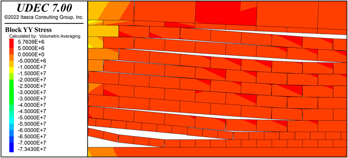
FIGURE 10. Delamination and rotary instability failure.
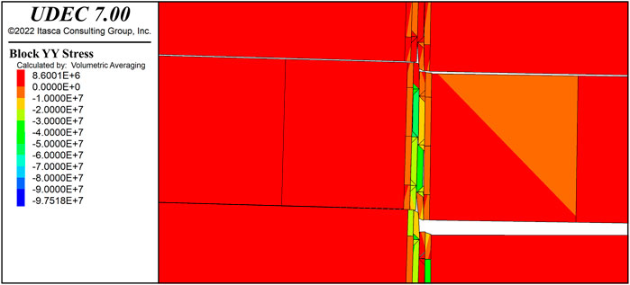
FIGURE 11. Blasting borehole damage.
After the second blasting, the cantilever made up of a long hard roof is further weakened. The mudstone in the hard roof fully collapses and fills the separation space generated by the first deep-hole blasting. The rock’s broken height rises rapidly and migrates violently, the stress changes sharply, and the accumulated energy released from the top cutting hole. The thick sandstone in the high layer above the working face suddenly bears great compressive stress, thus the extrusion shear failure occurs, as shown in Figure 12. On account of the energy accumulated in the high layer being much larger than that in the low layer, the possibility of major mining-induced seismicities increases. Combined with the field monitoring results, two large seisms with the energy of 105 J occur in the high layer above the working face after the second blasting. The simulation results are in accordance with the reality.
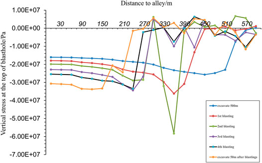
FIGURE 12. Vertical stress at the top of blast hole.
After the second blasting, the rock fully collapses and the space is filled. From Figure 13, the peak stress of the third and fourth blasting is significantly reduced, and lower than the peak stress of the working face without blasting. The peak compressive stress after blasting is in front of the working face and farther away from the working face. The newly emerged faults are mainly in the low layers, where the depth of mining-induced seismicities and their energy will be reduced. However, the frequency will be increased. Mining-induced seismicity events should be lower than the total number of events after either the first blasting or the second blasting.
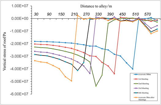
FIGURE 13. Vertical stress of roof.
From Figure 9F and Figure 9H, it can be concluded that the rock strata with top-cutting blasting are more likely to form step collapse. In this way, in the process of advancing the working face, the roof collapse rate will slow down, but the collapse will be more fully and gradually stable filling goaf behind the working face, which is conducive to safe production.
Based on the engineering background of the 63upper06 panel of Dongtan deep coal mine, we first investigate the spatial and temporal distribution of mining-induced seismicities before and after multiple deep-hole blastings, and then the stress and displacement in hard rock are simulated. Results reveal the mechanism of blasting weakening the thick and hard roof to prevent and control mining-induced seismicities. The main conclusions are as follows:
1) After deep-hole blasting, the mining-induced seismicities gradually transferred from the back of the working face to the solid coal side in front of the working face, with an increase in small mining-induced seismicities and an overall decrease in major seismicities. Small mining-induced seismicities are more concentrated within 20 m of the near field.
2) After deep-hole blasting, the crack propagation perpendicular to the direction of the maximum principal stress is inhibited. Delayed blasting could enlarge the range of the fractured zone and deepen the penetration between blasting holes.
3) The first deep-hole blasting may generate a large number of voids and abscission layers in the thick roof. After the second blasting, the rock mass breaks and collapses, with the stress changing rapidly, and cracks developing faster. After the stress released by the second deep-hole blasting, the peak stress decreases significantly after the third blasting, and the energy accumulated in the high strata reduces a lot. The mining-induced seismicities may be greatly diminished and mainly occur in the low layer.
4) Deep-hole blasting cuts off the upper roof, which is easier to form stepped collapse. The roof caving rate is reduced, making the roof collapse more fully as well.
In conclusion, the deep-hole blasting technology has a remarkable effect on weakening coal seam roofs and preventing and controlling large-energy mining-induced seismicities.
The original contributions presented in the study are included in the article/Supplementary Material, further inquiries can be directed to the corresponding authors.
XZ: investigation; CW: methodology; CZ: writing-original draft preparation; JZ and Y-YJ: writing-review and editing. All authors have read and agreed to the published version of the manuscript.
This work was supported by the China National Natural Science Foundation (Nos. 41731284, 41920104007, 42177152, and 41902293) and the Fundamental Research Funds for the Central Universities, China University of Geosciences (Wuhan) (Nos. 107-162301202609 and 107-162301212608).
XZ and CW were employed by the Company Shandong Energy Group Co., Ltd.
The remaining authors declare that the research was conducted in the absence of any commercial or financial relationships that could be construed as a potential conflict of interest.
All claims expressed in this article are solely those of the authors and do not necessarily represent those of their affiliated organizations, or those of the publisher, the editors, and the reviewers. Any product that may be evaluated in this article, or claim that may be made by its manufacturer, is not guaranteed or endorsed by the publisher.
Chen, B., and Liu, C. (2018). Analysis and Application on Controlling Thick Hard Roof Caving with Deep-Hole Position Presplitting Blasting. Adv. Civ. Eng. 2018 (1), 1–15. doi:10.1155/2018/9763137
Chun-rui, L., Li-jun, K., Qing-xing, Q., De-bing, M., Quan-ming, L., and Gang, X. (2009). The Numerical Analysis of Borehole Blasting and Application in Coal Mine Roof-Weaken. Procedia Earth Planet. Sci. 1 (1), 451–459. doi:10.1016/j.proeps.2009.09.072
Gibowicz, S. J., and Lasocki, S. (2001). Seismicity Induced by Mining: Ten Years Later. Adv. Geophys. 44, 39–181. doi:10.1016/S0065-2687(00)80007-2
Guest, A. R., Chitombo, G. P., and Grobler, H. P. (1995). Blast Optimization for Efficient Extraction of a Block Cave Undercut-Case Studies at De Beers Consolidated Mine Ltd., South Africa. Proc. EXPLO 95, 75–80.
He, H., Dou, L., Cao, A., and Fan, J. (2015). Mechanisms of Mining Seismicity under Large Scale Exploitation with Multikey Strata. Shock Vib. 2015 (8), 1–9. doi:10.1155/2015/313069
Holmquist, T. J., Johnson, G. R., and Cook, W. H. (1993). A Computational Constitutive Model for Concrete Subjected to Large Strains, High Strain Rates, and High Pressures. Proc. 14thInternational Symposium Ballist. 91 (22), 116–125. doi:10.1016/j.ijimpeng.2016.01.003
Hua, Z. S. (2019). Study on Rock Mechanics in Deep Mining Engineering. Chin. J. Rock Mech. Eng. 24 (16), 163449–163460. doi:10.1142/9789812772411_0003
Huang, B., Wang, Y., and Cao, S. (2015). Cavability Control by Hydraulic Fracturing for Top Coal Caving in Hard Thick Coal Seams. Int. J. Rock Mech. Min. Sci. 74, 45–57. doi:10.1016/j.ijrmms.2014.10.011
Jiao, Y.-Y., Wu, K., Zou, J., Zheng, F., Zhang, X., Wang, C., et al. (2021). On the Strong Earthquakes Induced by Deep Coal Mining under Thick Strata-A Case Study. Geomech. Geophys. Geo-energ. Geo-resour. 7 (7), 1. doi:10.1007/s40948-021-00301-1
Kan, J., Dou, L., Li, J., Li, X., Bai, J., and Wang, M. (2022). Characteristics of Microseismic Waveforms Induced by Underground Destress Blasting: Comparison with Those Induced by Ground Blasting and Coal Mining. Front. Earth Sci. 10, 797358. doi:10.3389/feart.2022.797358
Kutter, H. K., and Fairhurst, C. (1971). On the Fracture Process in Blasting. Int. J. Rock Mech. Min. Sci. Geomechanics Abstr. 8 (3), 181–202. doi:10.1016/0148-9062(71)90018-0
Liu, Z., Zhang, Y., Huang, Z., Gao, Y., and Zhang, Y. (2012). Numerical Simulating Research on Orifice Pre-splitting Blasting in Coal Seam. Procedia Eng. 45, 322–328. doi:10.1016/j.proeng.2012.08.165
Lu, A., Dou, L., Bai, J., Chai, Y., Zhou, K., Kan, J., et al. (2021). Mechanism of Hard-Roof Rock Burst Control by the Deep-Hole Blasting: Numerical Study Based on Particle Flow. Shock Vib. 2021 (5), 1–14. doi:10.1155/2021/9527956
Riedel, W. (2004). “Beton unter dynamischen Lasten: meso- und makromechanische Modelle und ihre Parameter,” in Institut für Kurzzeitdynamik, Ernst-Mach-Institut EMI. Editor Fraunhofer, (Freiburg/Brsg: Fraunhofer IRB Verlag). doi:10.1002/best.198500370
Senfaute, G., Chambon, C., Bigarré, P., Guise, Y., and Josien, J. P. (1997). Spatial Distribution of Mining Tremors and the Relationship to Rockburst Hazard. Pure Appl. Geophys. 150 (3-4), 451–459. doi:10.1007/s000240050087
Tang, Z. C., Wu, Z. L., and Zou, J. (2022). Appraisal of the Number of Asperity Peaks, Their Radii and Heights for Three-Dimensional Rock Fracture. Int. J. rock Mech. Min. Sci. 153, 105080–111609. doi:10.1016/j.ijrmms.2022.105080
Xie, L. X., Lu, W. B., Zhang, Q. B., Jiang, Q. H., Chen, M., and Zhao, J. (2017). Analysis of Damage Mechanisms and Optimization of Cut Blasting Design under High Iin-Ssitu Stresses. Tunn. Undergr. Space Technol. 66, 19–33. doi:10.1016/j.tust.2017.03.009
Zhang, Y., Du, C., Feng, G., Yuan, H., Deng, X., Zhang, R., et al. (2022). Study on the Law of Subsidence of Overburden Strata above the Longwall Gob. Geofluids 2022, 1–10. doi:10.1155/2022/6321031
Keywords: deep coal mining, deep-hole blasting, mining-induced seismicities, energy release, numerical simulation
Citation: Zhang C, Zou J, Zhang X, Wang C and Jiao Y-Y (2022) Study on the Mechanism of Weakening Thick and Hard Roof by Deep-Hole Blasting in Deep Coal Mines. Front. Earth Sci. 10:933192. doi: 10.3389/feart.2022.933192
Received: 30 April 2022; Accepted: 12 May 2022;
Published: 22 June 2022.
Edited by:
Shibing Huang, Wuhan University of Science and Technology, ChinaCopyright © 2022 Zhang, Zou, Zhang, Wang and Jiao. This is an open-access article distributed under the terms of the Creative Commons Attribution License (CC BY). The use, distribution or reproduction in other forums is permitted, provided the original author(s) and the copyright owner(s) are credited and that the original publication in this journal is cited, in accordance with accepted academic practice. No use, distribution or reproduction is permitted which does not comply with these terms.
*Correspondence: Junpeng Zou, em91anVucGVuZ0BjdWcuZWR1LmNu; Yu-Yong Jiao, eXlqaWFvQGN1Zy5lZHUuY24=
Disclaimer: All claims expressed in this article are solely those of the authors and do not necessarily represent those of their affiliated organizations, or those of the publisher, the editors and the reviewers. Any product that may be evaluated in this article or claim that may be made by its manufacturer is not guaranteed or endorsed by the publisher.
Research integrity at Frontiers
Learn more about the work of our research integrity team to safeguard the quality of each article we publish.