- 1College of Civil Engineering, Hunan City University, Yiyang, China
- 2School of Earth Sciences and Spatial Information Engineering, Hunan University of Science and Technology, Xiangtan, China
- 3Hunan Engineering Research Center of Structural Safety and Disaster Prevention for Urban Underground Infrastructure, Hunan City University, Yiyang, China
- 4Hunan Urban Construction College, Changsha, China
The studies on the steel pipe cutting and support stage in the pipe-roof pre-construction method (PPM) are rare, and their design lacks relevant standards, which is relatively conservative. Based on the Xinleyizhi Station of the Shenyang Metro construction case, MIDAS/GTS is used to study the stress of the original jacking steel pipes, supporting column, and surface subsidence under the influence of different construction parameters in the steel pipe cutting and support process in the PPM. The measured data are consistent with the numerical simulation results, which verifies the reliability of the numerical simulation results. With the increase of the distance between support columns, the maximum Mises stress of the original jacking steel pipe, the axial force of the support column, and the ground settlement gradually increase in a specific range. This indicates that the original design scheme can be optimized.
1 Instruction
The pipe-roof pre-construction method (PPM) is an unconventional method for large underground space construction. This method originates from the pipe-roof method. The PPM had been used in the Antwerp station (Musso, 1979; Hemerijckx, 1983) and Venezia Station on the Milan Rail (Lunardi, 1991; Lunardi, 1992) initially. This construction method has been applied in Korea widely, called the new pipe-roof method (Kim et al., 2003; Kwak et al., 2007). The construction method was introduced in China and is called the pipe-roof pre-construction method (Li et al., 2011a; Li et al., 2011b). At present, the engineering projects that have included this construction method in China include the Shenyang Metro Xinleyizhi station (Yang et al., 2017; Yang et al., 2018) and Yingze street passage under the Taiyuan railway station (Yang et al., 2020a; Yang et al., 2020b).
In the PPM, pipe cutting and support is the crucial stage to construct the pipe gallery, which is the vital process of mechanical transformation of the underground structure and is also a risky link in the entire construction process. The construction safety in this step is directly related to the entire project’s success. Studies about the PPM mainly focus on pipe jacking (Xiao et al., 2016; Zhang et al., 2016; Liu et al., 2018; Shi et al., 2018; Zhang et al., 2018; Jia et al., 2019), environmental effects (Ba et al., 2018; Yang et al., 2018; Jia et al., 2020) and mechanical behavior of the pipe roof (Xiao et al., 2016). Studies on steel pipe cutting and support in the PPM are rare. This study intends to analyze the stress of the original jacking steel pipes after cutting, the stress of the concrete-filled steel pipe support column, and the surface subsidence in the steel pipe cutting and support process in the PPM by numerical simulation. The numerical simulation results are compared with the field monitoring results to verify the authenticity.
2 Project Overview
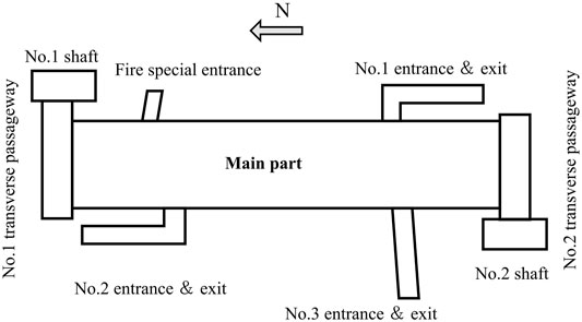
Xinleyizhi station is an underground island station with two floors, and the main part of the station is the single arch reinforced concrete structure. The total length of the station is 179.8 m, the width of the standard section is 26.2 m, and the height is 18.9 m. The buried depth of the bottom plate is 26.5∼30.1 m. The station is equipped with three entrances and exits and one fire special entrance, with a total construction area of about 9,800 m2. The foundation soil mainly comprises miscellaneous fill, sandy soil, gravel soil, and a small amount of cohesive soil. The layout plan of the project is shown in Figure 1.
The two shafts are constructed by open excavation, and the two transverse passageways and the main part of the station are constructed by the PPM. The specific process is as follows: taking the two completed shafts as the working shafts, the two transverse passageways are constructed by the PPM first. Then, taking the two transverse passageways as the working shafts, the main part is constructed by the PPM.
The construction process of the PPM is as follows: 1) in the working shaft, large-diameter steel pipes are jacked into the ground along the contour of the underground structure. 2) The pipe gallery is constructed by steel pipe cutting, support steel plates, and concrete-filled steel tubular columns. 3) The final structure of the underground structure is poured into the pipe gallery space. 4) After the structure construction is completed, large-area soil excavation is carried out under the protection of the structure, and the inner structures are built to construct the available underground space (Figure 2).
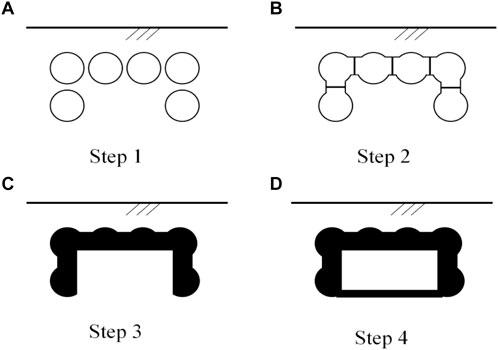
FIGURE 2. Schematic diagram of the PPM process. (A) Step 1: pipe jacking; (B) Step 2: pipes cutting and support; (C) Step 3: reinforced concrete construction; (D) Step 4: baseplate construction.
This study explores two pipe cutting and support at the top of the no. 1 transverse passageways. The size of the no. 1 transverse passageways is 22.1 × 11.8 m, and the steel pipe jacking length (longitudinal extension direction) is 35.4 m. The steel pipe diameter is 2.2 m, the thickness is 18 mm, and the pipe spacing is 255 mm. A total of 30 support columns are set in the longitudinal extension direction, and the distance between the support columns is 1.2 m. This project completes the steel pipe cutting and support process in two steps. First, the jacked steel pipes shall be cut at intervals. After the first cutting, the support steel plate and concrete-filled steel tubular support column shall be set. Then, the remaining part of the pipes is cut for the second time, and the support steel plate is set for the second time to construct an underground pipe gallery (Figure 3).

FIGURE 3. Pipe cutting and support. (A) Pipe cutting at intervals; (B) supporting first; (C) underground pipe gallery.
3 Numerical Simulation and Result Analysis
3.1 Overview of Numerical Simulation
Midas/GTS is used to establish the three-dimensional numerical model of two parallel pipe cutting and support according to the engineering background in the construction of no. 1 transverse passageways in the Xinleyizhi station. In the project, a total of 21 pipes need to be cut and supported in the no. 1 transverse passageways. If a complete numerical simulation analysis is carried out for all the pipes, due to the small size of support plates and columns, the number of calculation unit grids is huge, which may consume a lot of calculation resources, but it is difficult to obtain reasonable calculation results.
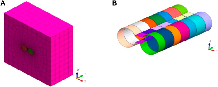
The diameter of the pipe is 2.2 m, the center distance between the two pipes is 2.46 m, and the top of the two pipes is 8.85 m from the ground. The bottom of the pipes is 8.85 m from the bottom of the model. The center of the left pipe is 8.57 m from the left wall of the model, and the center of the right pipe is 8.57 m from the right wall of the model. The longitudinal direction is the extension direction of the pipeline, and the total longitudinal length of the model is 5 m. The model’s boundary conditions are as follows: the upper surface is a free boundary without constraints. The left and right sides are constrained in the x-direction, the front and back sides are constrained in the y-direction, and the node displacement of the model’s bottom is fixed. The numerical simulation model is shown in Figure 4.
The calculation parameters of the stratum and other materials in the model calculation are shown in Table 1. The support column in actual construction is concrete-filled steel tubular. In the numerical simulation, the steel tubular and concrete are equivalent to one material according to the proportion of its cross-sectional area to assign the material parameters.
In the numerical simulation, the construction parameters of the actual construction scheme (such as case 1 in Table 2) are simulated, and the first cutting length and supporting column spacing (such as case 2∼5 in Table 2) are gradually increased. The specific construction parameters are shown in Table 2.
3.2 Analysis of Calculation Results
3.2.1 Axial Force Analysis of Support Columns
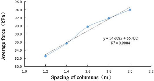
The axial stress nephograms of the middle support columns in case 1 to case 5 numerical simulations are shown in Figure 5. According to the stress nephograms of the support columns, the average axial force borne by each support column can be calculated. The relationship between the axial force borne by the support column and the distance of the support column can be analyzed, as shown in Figure 6.

FIGURE 5. Axial stress nephograms of the middle column in various cases (Unit: Pa). (A) Case 1; (B) case 2; (C) case 3; (D) case 4; and (E) case 5.
As shown in Figure 5, the axial stress of the support column gradually increases with the increase of the distance between the support columns and the most dangerous axial stress section is the lowest surface of the support column. In on-site engineering, the outer diameter of the concrete-filled steel tubular is 110 mm, the thickness of the steel tube is 4 mm, and the calculated steel content is 0.14. According to the national standard “Technical code for concrete-filled steel tubular structures” (GB50936-2014), the design compressive strength of the concrete-filled steel tubular is 45.6 MPa, which is far greater than the axial stress of the most dangerous section in case 5 (10.5 MPa). It indicates that even if the spacing of the support columns increases from 1.2 to 2 m, increasing by 66.7%, the compressive bearing capacity of the support column still has a large surplus.
As shown in Figure 6, the average axial force of the support column increases gradually with the increase of the distance between the support columns. There is a positive linear correlation between the axial force of the support column and the distance of the support column. When the distance between support columns increases from 1.2 to 2 m, increasing by 66.7%, the axial force of support columns increases from 82.5 to 94.0 kN, increasing by 13.9%. It shows that when the distance of support columns increases in a specific range, the axial force increment of support columns is limited.
3.2.2 Maximum Stress Analysis of Jacked Steel Pipes
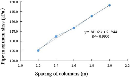
The maximum stress value of the jacking steel pipe is selected in the numerical simulation case 1∼ case 5. The relationship between the maximum Mises stress of the steel pipe and the distance of support column in the process of the cutting and support is analyzed, as shown in Figure 7.
As shown in Figure 7, with the larger distance of support columns, the maximum stress of the original jacked steel pipe gradually increases. This roughly conforms to the positive linear correlation. When the distance between support columns is 2 m, the maximum stress of the pipe reaches 148 MPa, which is less than the maximum yield stress of steel (235 MPa), and the steel pipe will not yield, and when the distance between support columns increases from 1.2 to 2 m, increasing by 66.7%, the maximum stress of the pipeline increases from 125 to 148 MPa, increasing by 15.5%. It shows that when the distance between support columns increases in a specific range, the maximum stress increment of the pipeline is limited.
3.2.3 Surface Subsidence
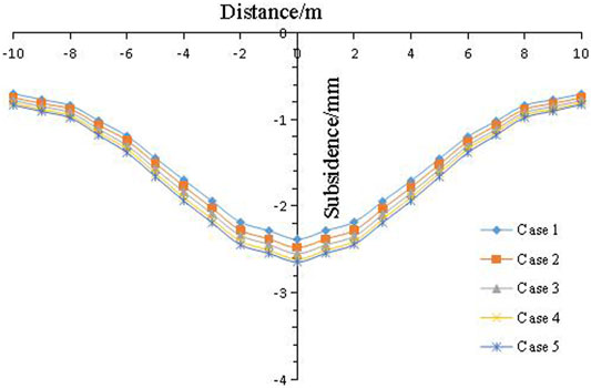
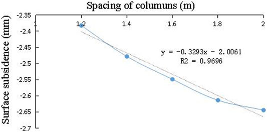
According to the surface transverse subsidence values, under all construction parameters in the case 1 to case 5 to draw the transverse surface settlement curve in various cases, as shown in Figure 7 (the ordinate origin in the Figure is the center position of two jacked pipes) and the relationship between the maximum settlement and the distance of support columns, as shown in Figure 9.
As shown in Figures 8, 9, the surface subsidence caused by the steel pipe cutting and support construction stage roughly conforms to the normal distribution under various construction parameters, with characteristics of the large settlements in the middle and small settlements on both sides. The greater the spacing between support columns, the severer the surface subsidence will be. The relationship between the maximum surface subsidence and the distance of support columns is approximately positively linear. When the distance of support columns increases from 1.2 to 2 m, increasing by 66.7%, the maximum ground subsidence increases from 2.4 to 2.6 mm, increasing by 8.3%. It shows that when the distance between support columns increases within a specific range, and the maximum increment of the ground subsidence is limited.
4 Comparative Analysis of Numerical Simulation and Measured Results
4.1 Numerical Simulation and Calculation of Axial Force of the Steel Pipe
The axial pressure of concrete-filled steel tubular is
Comprehensive elastic modulus of the reinforced concrete steel tubular
According to the comprehensive elastic modulus, the axial pressure of the concrete-filled steel tubular is
The axial pressure of the steel tubular is
The outer diameter of the steel tubular is 110 mm, and its thickness is 4 mm. The area of steel tubular and concrete can be obtained. According to Eq. 4, the relationship between the axial pressure of the steel tubular and the axial pressure of the concrete-filled steel tubular can be obtained
where Fy0 is the axial pressure of the concrete-filled steel tubular, kN; Fs is the axial pressure of the steel tubular, kN; Fc is the axial pressure of the concrete, kN; σs is the axial stress of the steel tubular, MPa; σc is the axial stress of the concrete, MPa; As is the area of the steel tubular, mm2; Ac is the area of the concrete, mm2; ε is the axial strain of the concrete-filled steel tubular; Es is the elastic modulus of the steel tubular, MPa; Ec is the elastic modulus of the concrete, MPa; and E1 is the elastic modulus of the concrete-filled steel tubular, MPa.
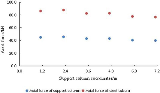
According to the axial force of the support column calculated by the numerical simulation, the axial force of the steel tubular of each support column in the numerical simulation model can be obtained by Eq. 5.
As shown in Figure 10,the maximum axial force of each support column in the longitudinal direction calculated by the numerical simulation in case 1 is 87.9 kN, and its minimum value is 76.7 kN. Accordingly, the maximum axial force of the steel tubular is 45.8 kN, its minimum axial force is 40 kN, and the average axial force of each steel tubular is 42.9 kN.
4.2 Comparative Analysis of Axial Force of Steel Tubular
In the actual construction process, in order to ensure the construction time limit, some construction procedures are carried out alternately. For example, the lower part is still jacking, and the upper part has begun cutting and supporting. Therefore, it is impossible to accurately monitor the structural stress and surface settlement in the whole cutting and supporting process. So, the field monitoring data in cutting and support of the leftmost two pipes (the first two pipes to be cut and supported) are studied.
During the construction of no. 1 transverse passageways via pipe cutting and support, four steel tubulars are selected from the top layer’s two rows of support columns for axial force monitoring. A total of eight steel pipe axial force monitoring sensors are set, and the monitoring frequency is once a day. The axial force monitoring results of the support column are shown in Figure 11.
It can be seen that the monitoring results of the measuring points, except sensor 1 and sensor 7, are close to the average value of numerical simulation calculation (42.89 kN). The monitoring results are consistent with the numerical simulation results which verify the reliability of the numerical simulation.
4.3 Comparative Analysis of Surface Subsidence
During the construction of steel pipes on the top layer of no. 1 transverse passageways via pipe cutting and support, surface subsidence monitoring points are set for continuous construction monitoring, and its monitoring frequency is once a day. Taking the construction of the leftmost two pipes of no. 1 transverse passageways via pipe cutting and support as an example, the measured surface subsidence is analyzed in the article. The layout of monitoring points and the location of monitoring points in the cross-section are shown in Figure 12.
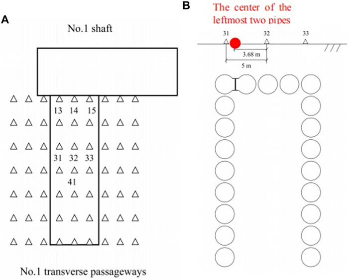
FIGURE 12. Monitoring results of axial force of the steel pipe. (A) Layout of monitoring points. (B) Location of monitoring points in the cross section.
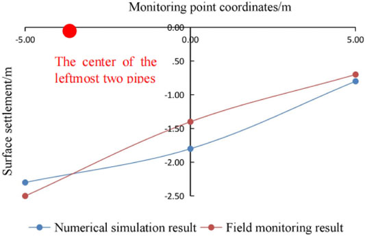
In the actual monitoring process, partial points are selected for long-term monitoring (the points marked with point numbers in Figure 11 are long-term monitoring points). The monitoring section formed by points 31, 32, and 33 in the Figure is the middle section, which is representative. The measured results of the middle section are selected to analyze the surface subsidence monitoring results during the construction of the leftmost two pipes via pipe cutting and support. Point 32 is located at the no. 1 transverse passageways centerline, and the distance between the two points is 5 m. The distance between the midpoint of the leftmost two jacking pipes and the point 32 is 3.68 m. The typical surface subsidence transverse curve is shown in Figure 13.
Through the comparison with the numerical simulation results of the surface subsidence, it can be seen that although the measured points are not arranged at the center of the two pipes, they are still consistent with the numerical simulation results. The measured cumulative maximum subsidence value is 2.5 mm, which is slightly larger than the numerical simulation results of the corresponding points (2.3 mm). The farther it is from the center of the two pipes, the smaller the subsidence value.
5 Conclusion and Suggestions
1) MIDAS/GTS is used to analyze the steel pipe cutting and support construction stage in the PPM. The effects of gradually increasing the distance of support columns on the maximum Mises stress of the original jacking steel pipe, the axial force of support columns, and the surface subsidence are studied. The numerical simulation results show that when the distance of support columns increases from 1.2 to 2 m, that is 66.7%, the axial force increment of the support column, maximum Mises stress of original jacking steel pipe, and surface subsidence are 13.9, 15.5, and 8.3%, respectively. The maximum axial force of the support column is less than its compressive strength, and the maximum Mises stress of the original jacking steel pipe is less than its yield strength. It shows that when the distance of support columns increases within a specific range, the maximum Mises increment of the original jacking steel plate, the axial force of support columns, and surface subsidence are restricted.
2) The numerical simulation results and on-site monitoring results of axial force of support columns and the surface subsidence in the pipe cutting and support stage are compared. The monitoring results of the most axial force measurement points are close to their numerical simulation calculation average value (42.9 kN). The measured cumulative maximum surface subsidence value is 2.5 mm, slightly larger than its numerical simulation result (2.3 mm). The changing trend of the measured value is the same as that of the numerical simulation value. The farther it is from the center of the two pipes, the smaller the subsidence value will be. The numerical simulation results are consistent with the monitoring results, which proves the reliability of the monitoring results.
3) In the PPM, the pipe cutting and support are crucial for the underground pipe gallery construction. At present, rare studies focus on the pipe cutting and support. Its design lacks standard guidance, and its relevant on-site monitoring data are insufficient. The results in this study show that the original design scheme of this study still needs to be improved.
Data Availability Statement
The original contributions presented in the study are included in the article/Supplementary Material; further inquiries can be directed to the corresponding author.
Author Contributions
Field monitoring, XY and YoL; numerical simulation, YaL and ZY.
Funding
This research was funded by the Natural Science Foundation of Hunan Province (2021JJ30078).
Conflict of Interest
The authors declare that the research was conducted in the absence of any commercial or financial relationships that could be construed as a potential conflict of interest.
Publisher’s Note
All claims expressed in this article are solely those of the authors and do not necessarily represent those of their affiliated organizations, or those of the publisher, the editors, and the reviewers. Any product that may be evaluated in this article, or claim that may be made by its manufacturer, is not guaranteed or endorsed by the publisher.
References
Ba, F., Chen, J., and Shi, H. (2018). “Performance of New Tubular Roof Construction Method - A 3D Numerical Investigation,” in Proceedings of the 2018 Int Conference on Engineering Simulation and Intelligent Control (ESAIC), Hunan, China, Aug. 11 2018 (IEEE).
Hemerijckx, E. (1983). Tubular Thrust Jacking for Underground Roof Construction on the Antwerp Metro, Part 1. Tunn. Tunn. Int. 15 (5), 13–16. doi:10.1016/0148-9062(83)90151-1
Jia, P., Jiang, B., and Zhao, W. (2019). Calculating Jacking Forces for Circular Pipes with Welding Flange Slabs from a Combined Theory and Case Study. KSCE J. Civ. Eng. doi:10.1007/s12205-019-0977-2
Jia, P., Zhao, W., and Arman, K. (2020). A New Model to Predict Ground Surface Settlement Induced by Jacked Pipes with Flanges. Tunn. Undergr. Space Technol. 98 (2), 1–16. doi:10.1016/j.tust.2020.103330
Kim, J. Y. (2003). The Method of Building Underground Structure Using the Space in the Steel Pipes Injected to the Ground. Application of New Technology Authorization. Seoul, Korea: Ministry of Construction and Transportation.
Kwak, C. W. (2007). Seismic Behavior of Tubular Roof & Trench Method (T.R&T) by Numerical Analysis. Underground Space - the 4th Dimension of Metropolises , Landon, 513–518.
Li, Y., Zhang, K., and Huang, C. (2011). “Analysis of the Ground Deformation to Large Crosssection Tunnel by Pipe-Roof Pre-construction Method,” in Second International Conference on Mechanic Automation & Control Engineering, 15-17 July 2011 (IEEE). doi:10.1109/MACE18262.2011
Liu, J., Ma, B., and Cheng, Y. (2018). Design of the Gongbei Tunnel Using a Very Large Cross-Section Pipe-Roof and Soil Freezing Method. Tunn. Undergr. Space Technol. 72, 28–40. doi:10.1016/j.tust.2017.11.012
Lunardi, P. (1991). Cellular Arch Technique for Large-Span Station Cavern. Tunn. Tunnell. Int. 23 (11), 23–26. doi:10.1016/0148-9062(92)91006-q
Lunardi, P. (1992). Method for Building Large Span Tunnels by Means of a Cellular Arch. Milano, Italy: US, EP0332799. [P].
Musso, G. (1979). Jacked Pipe Provides Roof for Underground Construction in Busy Urban Area. Civ. Eng. 49 (11), 79–82. doi:10.1016/0360-1323(79)90007-6
Shi, P., Liu, W., Pan, J., and Yu, C. (2018). Experimental and Analytical Study of Jacking Load during Microtunneling Gongbei Tunnel Pipe Roof. J. Geotech. Geoenviron. Eng. 144 (1), 05017006. doi:10.1061/(asce)gt.1943-5606.0001801
Xiao, J., Dai, F., Wei, Y., Xing, Y., Cai, H., and Xu, C. (2016). Analysis of Mechanical Behavior in a Pipe Roof during Excavation of a Shallow Bias Tunnel in Loose Deposits. Environ. Earth Sci. 75 (4), 1–18. doi:10.1007/s12665-015-5176-y
Yang, S., Wang, M., and Du, J. (2020a). Research of Jacking Force of Densely Arranged Pipe Jacks Process in Pipe-Roof Pre-construction Method. Tunn. Undergr. Space Technol. 97 (3), 1–10. doi:10.1016/j.tust.2019.103277
Yang, S., Wang, M., and Du, J. (2020b). Influence of Construction Sequence of Pipe Jacking by Pipe-Roof Pre-construction Method on Ground Surface Settlement. J. Zhejiang Univ. Eng. Sci. 54 (09), 1706–1714. doi:10.3785/j.issn.1008-973X.2020.09.006
Yang, X., and Li, Y. (2018). Research of Surface Settlement for a Single Arch Long-Span Subway Station Using the Pipe-Roof Pre-construction Method. Tunn. Undergr. Space Technol. 72, 210–217. doi:10.1016/j.tust.2017.11.024
Yang, X., and Liu, Y. (2017). Monitoring and Controlling on Surface Settlement in Sand and Gravel Strata Caused by Subway Station Construction Applying Pipe-Roof Pre-construction Method (Ppm). Cej 26, 179–188. doi:10.14311/cej.2017.02.0016
Zhang, H., Zhang, P., Zhou, W., Dong, S., and Ma, B. (2016). A New Model to Predict Soil Pressure Acting on Deep Burial Jacked Pipes. Tunn. Undergr. Space Technol. 60, 183–196. doi:10.1016/j.tust.2016.09.005
Zhang, P., Behbahani, S. S., Ma, B., Iseley, T., and Tan, L. (2018). A Jacking Force Study of Curved Steel Pipe Roof in Gongbei Tunnel: Calculation Review and Monitoring Data Analysis. Tunn. Undergr. Space Technol. 72, 305–322. doi:10.1016/j.tust.2017.12.016
Keywords: pipe-roof pre-construction method, pipe cutting and support, structural stress, surface subsidence, field measurement
Citation: Yang X, Liu Y, Li Y and Yang Z (2022) Research of Pipe Cutting and Support in the Pipe-Roof Pre-Construction Method. Front. Earth Sci. 10:930764. doi: 10.3389/feart.2022.930764
Received: 28 April 2022; Accepted: 23 May 2022;
Published: 01 July 2022.
Edited by:
Mingfeng Lei, Central South University, ChinaReviewed by:
Pengjiao Jia, Soochow University, ChinaJianyong Han, Shandong Jianzhu University, China
Yang Songsong, Southeast University, China
Copyright © 2022 Yang, Liu, Li and Yang. This is an open-access article distributed under the terms of the Creative Commons Attribution License (CC BY). The use, distribution or reproduction in other forums is permitted, provided the original author(s) and the copyright owner(s) are credited and that the original publication in this journal is cited, in accordance with accepted academic practice. No use, distribution or reproduction is permitted which does not comply with these terms.
*Correspondence: Zeyu Yang, NjkxMDE1MDU4QHFxLmNvbQ==
 Xian Yang
 Yang Liu2
 Yongsuo Li