
95% of researchers rate our articles as excellent or good
Learn more about the work of our research integrity team to safeguard the quality of each article we publish.
Find out more
ORIGINAL RESEARCH article
Front. Earth Sci. , 06 July 2022
Sec. Geohazards and Georisks
Volume 10 - 2022 | https://doi.org/10.3389/feart.2022.921716
This article is part of the Research Topic Rock Avalanche, Landslide and Debris Flow Hazards in Mountainous Areas View all 15 articles
 Shuai Li1,2
 Xiaoqing Chen1,2,3
 Jiangang Chen1,2,3*
 Hui Tang4
 Yong You1,2
 Huayong Chen1,2
 Wanyu Zhao1
 Xueyu Geng5
Drainage channels are widely used for discharging debris flows into deposition basins or rivers. However, the current drainage channel designs for guiding rapid debris flows downstream do not account for the variations of the gullies’ gradient and debris flow energy. In this study, we evaluated the performance of different step-baffle geometries (square, triangle, and trapezoid) in regulating debris flows. Specifically, their effects on the flow patterns, sediment transport, energy dissipation, and impact pressure are investigated using flume experiments. Results here showed that the square baffles promote highly turbulent flows which in turn result in the highest lift height relative to the triangular and trapezoidal baffles. Maximum sediment interception and highest energy dissipation are obtained using the trapezoidal baffle, whereas the triangular baffle exhibits minimal solid interception and the lowest energy dissipation. Trapezoidal baffles generally experience the greatest impact forces relative to both square and triangular baffles. However, when only the first baffle in the channel is considered, it is the square baffles that experience the largest impact forces. The present work improves the understanding of the effectiveness of step-baffle drainage channels in mitigating debris flows.
A drainage channel is an engineering mitigation measure designed to protect residents, facilities, and infrastructures from debris flows. Generally, it works in association with the channel control works (Chen X. et al., 2015; Ozturk et al., 2018; Bernard et al., 2019; Marchi et al., 2019). Drainage channels are widely implemented in the basins of downstream areas (VanDine 1996) with the primary goal of discharging the debris flows. Due to its relevance to disaster mitigation, several works have been dedicated to the improvement of debris flow drainage channel design.
Debris flows were previously treated as sand-carrying floods or hyper-concentrated flows. Hence, civil engineers have designed debris-flow drainage channels similar to spillways in hydropower dams. In most cases, the debris flow drainage channels were designed according to the general flood magnitude of flows along flat-bottomed trapezoidal or rectangular cross sections. However, since the solid content in debris flows is much larger than that of floods or hyper-concentrated flows, there is significant scouring, impact, and abrasion on the channel. To minimize the damage due to erosion and abrasion, two debris flow drainage channels were proposed, i.e., Dongchuan-type and V-type drainage channels (Figures 1A,B), which became widely adopted between the 1960s and 1980s in China. The Dongchuan-type drainage channels are characterized by a series of sills that are embedded in the soil. The sills minimize the erosion of the valley bed. When debris flows, mixed with the sediment soil, interact with the sills, flow energy is dissipated, thereby protecting the downstream area. This type of drainage channel is suitable for terrains having slopes of 5–20% (Li, 1997; Huang et al., 2009). However, at gentler slopes (less than 5%), debris flows tend to deposit due to having low velocities and high basal resistance. To overcome this limitation, the V-type drainage channels were proposed and applied in the Laogan gully, Yunnan province (You and Liu, 2008; You et al., 2011). The full section of concrete included in this design reduces the roughness of the drainage channel, which increases the flow velocity and discharge capacity, thereby alleviating siltation.
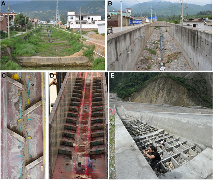
FIGURE 1. Different types of debris flow drainage channels (A) Dongchuan-type; (B) V-type; (C) SIS-type; (D) OSS-type; (E) PRCB-type.
External perturbations resulting from large earthquakes (e.g. 12 May 2008 Wenchuan MS 8.0 earthquake) can alter local geographic and geomorphic conditions in mountain areas which in turn change local debris flow characteristics. The steeper slopes (more than 20%) and smaller watersheds (less than 5 km2), which may result from the large earthquake events, increase debris flow velocities and bulk densities (Cui et al., 2010). In these situations, it is necessary to explore new technologies and drainage channel designs that improve energy dissipation and resistance from wearing (erosion).
In the past decade, three representative debris flow drainage channels with energy dissipation structures were proposed: 1) staggered indented sills (SIS) (Chen et al., 2014) (Figure 1C), 2) oblique symmetrical sills (OSS) (Wang et al., 2018) (Figure 1D), and 3) pre-fabricated reinforced concrete boxes (PRCBs) (Figure 1E) (Chen et al., 2016; Chen J. et al., 2017). Compared to the Dongchuan-type and the V-type drainage channels, the SIS-type and OSS-type drainage channels increase the bed friction and improve the velocity reduction ratios by a factor of two, thereby increasing the energy dissipation. The PRCB-type drainage channel can effectively enhance the flow resistance and relieve bed erosion when the debris flow passes over the concrete boxes. Energy is dissipated through the strong interactions between the debris flow and the rocks in the box structure. The maximum energy dissipation ratio of the PRCB-type drainage channel may be more than 50%, as suggested by Chen et al. (2016). Although the abovementioned debris flow drainage channels have been studied and used in practice for more than 60 years, universal drainage channel designs are still not available. The continuous variation of geological settings induced by large earthquakes and extreme rainfall results in abundant sediment sources and steeper valleys which subsequently promotes larger and more frequent debris flows (Cui et al., 2010). These variabilities force us to design new types of drainage channels that are able to accommodate current debris flow characteristics.
Step-pool geomorphologic systems are a common phenomenon in steep mountain terrains (3–30%) (Figure 2A). This self-organized bed configuration can enhance channel resistance, decrease velocity, and extensively dissipate flow energy (Chin 2002; Comiti et al., 2009; Wilcox et al., 2011; Golly et al., 2019; Saletti and Hassan 2020; Zimmermann et al., 2022). In addition, stepped cascades (Figure 2B) are known to significantly dissipate hydraulic energy in hydraulic engineering (Chanson 2001; Matos and Chanson 2006; Bung et al., 2012; Felder et al., 2019; Zhang et al., 2019). Inspired by these two naturally occurring structures, a similar system, step-baffle drainage channels were introduced to mitigate debris flows (Figure 2C). This type of drainage channel is composed of a sequence of steps and baffles, resembling a staircase.
The goal of this study was to systematically investigate the performance of the new step-baffle drainage channel in terms of four evaluation indexes (Figure 2D). Previous works have shown that debris flow velocity has a positive relationship with channel gradients (Chen et al., 2014). Averaged velocities decreased by 14.2–51.1%, 28–40%, and 27.3–39.3% for OSS-type drainage channels (Wang et al., 2018), step-pool configurations (Chen X. et al., 2017), and energy dissipation baffles (Wang et al., 2017), respectively. Particularly, the energy dissipation in step-pool channels increases gradually with the length and width of the channel (Wang et al., 2012; Chen J. et al., 2015; Chen X. et al., 2015). Other key parameters, such as the step height, pool length, and step-pool gradient were investigated by Abrahams et al. (1995), Chin (1999), Chartrand and Whiting (2000), and Wooldridge and Hickin (2002). Chen et al. (2018) recommended an expression to calculate the roughness coefficient of a drainage channel with an energy dissipation structure. The work of Chen X. et al. (2017) proposed design guidelines for the shape and total length of a single step-pool configuration, as well as the slope of the step. Li et al. (2020) systematically studied the impact pressure on steps and baffles based on the stability of the drainage channel and recommended an expression to predict impact pressure by considering the baffle shape.
The abovementioned works have only considered one variable or aspect of debris flow drainage channels, and very few of them incorporate sediment transportation, energy dissipation, and impact pressure to make a comprehensive performance evaluation of drainage channel designs. There has also been no research that has focused explicitly on debris flow drainage channels with step-baffles.
In the present study, the authors reported detailed experimental tests on drainage channels with baffles having three geometric shapes (square, triangle, and trapezoid). Using these experiments, we investigated the relationships between baffle geometry and their regulation efficiency, specifically on (1) the variation of longitudinal debris flow patterns along with the step-baffle sequences; 2) the variation of the solid fraction in debris flows across the drainage channel; 3) the efficiency of step-baffles in dissipating debris flow energy; and 4) the performance of impact-resisting baffles. Finally, we briefly discussed the development of debris flow drainage channels, their applicability, and recommendations for different drainage channel designs.
The experimental tests are carried out in the Dongchuan Debris Flow Observation and Research Station (DDFORS), Chinese Academy of Sciences, in Yunnan Province, China. The experimental flume used for modeling is composed of a sequence of steps and baffles, resembling a staircase. The configurations and dimensions of the experimental tests are shown in Figure 3. The angle of inclination of the flume is fixed (θ = 8.5°, 0.45 m width, 0.40 m depth, and 6.0 m length). Debris flow materials are stored and released from a tank upstream, while a tailing pool is situated downstream. Five artificial step-pool sequences (from 1# to 5#) are installed starting at 1.8 m from the tank entrance with an interval of 0.27 m along the flume. The wall of the flume is in glass, which allows for observation of the flowing processes. The baffles used in this study have three shapes: square (0.04 m × 0.04 m×0.45 m), triangle (0.04 m × 0.04 m×0.45 m), and trapezoid (0.04 m bottom length, 0.02 m top length, 0.04 m height, and 0.45 m width), which come into contact with the debris flows with faces inclined at β = 90°, 63°, and 45°, respectively (Figure 3). At the start of each experiment, the debris flow samples are released onto the flume by a manual gate at the bottom of the tank and are collected at the end of the flume. To prevent sedimentation of the materials in the tank, a hand-held electric mixer continuously stirs the samples before the release of the mixture. The repeatability of manual operation is checked within an error of ±0.05s.
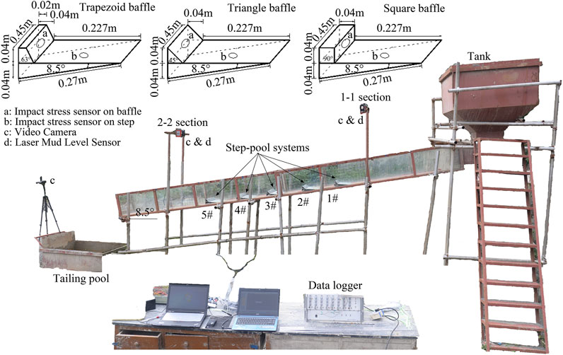
FIGURE 3. Schematic diagram of the test equipment, baffle configurations and impact pressure measurement points.
Five impact stress sensors (LH-Y127B, 2000 Hz, with a range of 0–100 N, and accuracy of ±1.0 %) with a diameter of 25 mm are used to record the impulsive force on stationary load frames (Pa1-Pa5) placed on the center of the baffles along the flume (Figure 3). Other measuring devices are installed in two sections (i.e., 1-1 and 2–2), which are mounted near the start (1.5 m) and close to the end of the flume (1.0 m), respectively. The equipment set includes two mud level laser sensors (Leuze, ODSL 30/V-30M-S12, 10 Hz) with a resolution of ±1.0 mm to measure the temporal variations of debris flow depth. Three video cameras (SONY FDR-AX40, 1,440 × 1,080 pixels, 25 fps) are installed to capture the debris flow process and the debris flow impacts on the step-baffles. To measure the velocity of the debris flow front, we marked reference lines with an interval of 0.1 m at the bottom of the flume in sections 1-1 and 2–2. The debris flow velocity can be estimated (within an error of about ±0.1 m/s) from the video recordings of the motion of the flow front with respect to the reference lines.
The experimental mixture materials are prepared based on water combined with solid particles obtained from natural debris flow deposits in the Jiangjia Ravine, China, which has a bulk density of 2,680 kg/m3. The mass of dry sediment is kept constant at 200 kg, while the water content is varied. Material densities are controlled by varying the water content, namely, high water contents (or low solid volume fraction) correspond to bulk materials with low debris flow density (see Table 1). For each type of baffle, five source material sets (M1–M5) are used (i.e., 15 experimental tests in total). The sediment grain size ranges from 0.001 to 20 mm, with d50 = 5.1 mm. The maximum used grain diameter of 20 mm was defined in accordance with the maximum height of the baffles (40 mm), as well as the size of the impact area of each aluminum device (diameter equals 25 mm) within the force plate. Figure 4 shows the cumulative grain size distribution (GSD) curve of the granular materials. A summary of the source material properties (density, solid volume fraction, yield stress, and dynamic viscosity) and Froude numbers of debris flow at the 1-1 section is listed in Table 1.
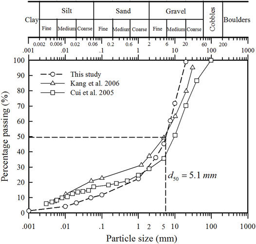
FIGURE 4. The cumulative grain size distribution of the debris-flow materials adopted in this study and datasets from Jiangjia Gully (cf. Cui et al. 2005 and Kang et al. 2006).
Directly measuring the regulation of drainage channels on debris flows in the field or in large-scale experiments usually does not require scaling considerations. However, it is difficult to obtain direct measurements in the field due to the infrequent, unpredictable, and destructive features of debris flow events, and large-scale experiments are costly. For these reasons, small-scale flume experiments are preferred for studying debris flows (Zhou and Ng 2010; Iverson 2015).
To ensure that debris flow experiments are representative of their larger natural counterparts, certain similarity criteria need to be taken into account. In this study, we do not consider the geometric similarity because our work does not represent a specific real-world scenario. The kinematic similarity is characterized by the Froude number, Fr, which represents the ratio of bulk inertia to the gravitational forces acting on the flowing mass, i.e., Fr = v/(gh)0.5, where v is the flow velocity, g is the acceleration due to gravity, and h is the flow depth. Fr governs the dynamic behavior of mass flow in open channels, which has been identified and validated as a major parameter for scaling debris-structure interactions (Hübl et al., 2009; Armanini et al., 2011). The Fr used in the experiments is made similar to natural debris flow events which are usually less than 5.0 (Hübl et al., 2009; Cui et al., 2015). In this study, the flow velocities and depths measured in section 1-1 range from 2.8 to 3.4 (see Table 1) and are therefore representative of natural debris flows.
The debris flow pattern is one of the fundamental indicators used to evaluate the performance of step-baffle systems. The measurement time starts (t = 0 s) when the source material is released from the storage tank. The flow surface profiles of the five debris flow densities in section 1-1, before they make contact with the first baffle, are shown in Figure 5. The flow depth prior to coming into contact with the first baffle is generally similar in the different tests: it initially rapidly increases until it reaches a peak value after which it slowly decreases with several small magnitude surges. The peak flow depth slightly decreases with the increase in the solid volume fraction. It is also observed that the debris flow front arrives at section 1-1 after ∼ 0.4 s for all cases, with a slight delay for those with high solid volume fractions. This may be attributed to the difference in viscosity in debris flows since flows with a high solid fraction exhibit more evident viscous behavior which then results in greater internal resistance and lower velocity.
The evolution of debris flow surface profiles for the three types of baffles in drainage channels for a typical debris flow having a solid volume fraction of Cs = 0.55 is shown in Figure 6. When the debris flow front impacts the first baffle, the flowing material is propelled sharply into the air, which later drops onto the downstream step-baffles. The downstream baffles in turn lift the debris flow materials again until they eventually reach the end of the flume. The maximum lift height is observed after the first baffle for all three types of step-baffle channels. Generally, the debris flows in the step-baffle drainage channel are similar to wave-like flows with very chaotic flow surface patterns. Also, the wavy flow is induced by step-baffle systems, which in turn increases the debris flow height.
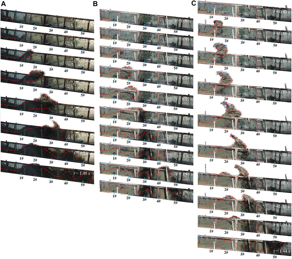
FIGURE 6. The evolution of debris flow profiles (Cs = 0.55) in the drainage channel: (A) step + triangular baffle; (B) step + trapezoidal baffle; and (C) step + square baffle.
It is also observed in Figure 6 that the maximum heights of the flows propelled upon impacting the square, triangle, and trapezoidal baffles exceed the height of the sidewalls by 0.6, 0.35, and 0.2 m, respectively. These results indicate that a higher sidewall may be needed to avoid the debris splashing out for the step-baffle drainage channel. The position associated with the maximum lift height is closer to the second baffle in the square baffle system than it is for the triangle and trapezoidal systems in which they fall between the second and third baffles. These results are due to the different inclination angles of the upwind face of baffles (Figure 2). The upwind face of the square baffle, inclined at 90°, results in a greater and more abrupt change of the flow direction than the trapezoidal (60°) and triangular (45°) systems.
A natural consequence of step-baffle channels is step pools which trap portions of the sediments in debris flows. The remaining debris and water mixture will continue to move downstream. The regulatory performance of the step-baffle channel varies with the geometry of the baffle and the property of incoming debris flows. In this study, the sediment-trapping ratio, κ, is used to quantify the regulatory performance of step-baffle channels on debris flows. The ratio κ is formally written as follows:
where Csori is the solid fraction of the source mixture, and Cs is the solid fraction collected behind each step-baffle. When κ < 1, Cs of the trapped volume is less than that of the source material. On the other hand, κ > 1 indicates relatively larger amounts of sediments confined behind a baffle.
The sediment-trapping ratio κ at the different types of baffles as well as at the outlet of the channel is shown in Figure 7. Generally, the sediment-trapping ratio is less than 1.0 at the first step-baffle and at the channel outlet, whereas κ > 1 at the 3rd and 5th step-baffles (Figures 7A–C). In other words, less amount of sediments are trapped in the 1st step-baffle; however, since the trapping is highly efficient at the middle baffles, very little solid material is transported downstream. The sediment-trapping ratio at the outlet of the channel is less than 1.0 (in the range of 0.96–0.98, see Figure 7D), which confirms that the solid fraction is decreased after the regulation by step-baffle systems. This consequently results in the reduction of damage caused by solids in debris flows. These results indicate that all three types of baffles are able to regulate debris flows well. The value of κ at the channel outlet decreases with the increase in Csori (Figure 7D). This implies that the regulatory performance of the step-baffle channel is better when the incoming debris flow becomes viscous.
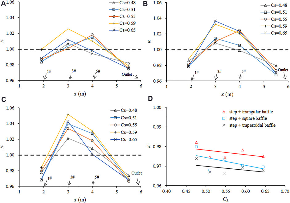
FIGURE 7. The sediment-trapping ratio for the (A) triangular baffle; (B) square baffle; (C) trapezoidal baffle; and (D) channel outlet.
It can also be observed from the values of κ in the 3rd and 5th step-baffles in Figure 7 that a trapezoidal design results in the most efficient trapping of sediments. This is followed by the square baffles and the triangular baffles. This is somewhat surprising since one would expect the design with the steepest face angle would be more effective in stopping and trapping flowing sediments. The reason for this is not clear, but it may be related to the maximum height of the propeller flow.
The primary purpose of drainage channels is to quickly discharge debris flows downstream. However, high-speed debris flows with immense energy may cause severe damage to the downstream area. Therefore, the drainage channel should be able to dissipate as much energy as it is discharging the debris flow. In this study, the addition of step-baffle systems in the conventional drainage channel is to dissipate debris flow energy.
The energy dissipation principle of the step-baffle drainage channel lies in two aspects. 1) Due to the drop space between the upper and lower steps, a cavity is often formed there. Under the shear of the high-speed debris flow in the upper part of the cavity, the debris flow inside the cavity is driven to form a strong turbulent vortex in the cavity. The cyclic shear in the vortex cavity reduces the energy of debris flow. 2) The baffles and steps roughen the channel bed and provide resistance to the debris flows and effectively consume the debris flow energy.
Debris flows are special fluids; therefore, the energy balance governing the debris flow in the flume experiments from initiation to end can be described in terms of fluid mechanics. The energy balance approach is commonly used to calculate the energy dissipation in debris flow drainage channels (Chen J. et al., 2015; Choi et al., 2015; Chen X. et al., 2017). It is assumed that the movement of debris flows in a flume is similar to uniform flows. Then, the total energies at the cross sections 1–1 and 2–2 (Figure 3) are as follows:
Hence, the expression of the energy dissipation ratio, η, can be calculated as follows:
where Δz is the potential energy difference between sections 1-1 and 2–2; θ is the channel slope; h1 and h2 are debris flow depths, and v1 and v2 are the time-averaged surface velocities of debris flows at sections 1-1 and 2–2, respectively; α1 and α2 are the kinetic energy correction factors (α1 = α2 ≈ 1.0); g is gravity acceleration.
Figure 8 shows that the energy dissipation ratio η clearly increases with the debris flow solid friction Cs for different types of baffles. This implies that the step-baffle channel dissipates more energy when debris flows hold a higher solid fraction (i.e., viscous debris flow). The most surprising result in Figure 8 is that the energy dissipation ratio in the trapezoidal baffle is the largest, while that of the triangular baffle is the smallest.
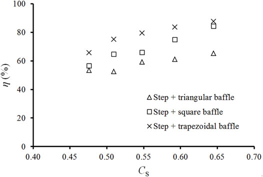
FIGURE 8. Variation of the energy dissipation ratio κ with solid fraction of the with incoming debris-flow.
The impact force of debris flows quantifies its destructive potential toward structures. A good step-baffle channel should have a strong impact-resisting ability. The baffle, being the key component in step-pool systems, is the most vulnerable to the impacts of debris flows and ought to be the pivotal object to study.
Generally, the peak impact pressure is the critical factor causing structural damage to baffles. Therefore, the ratio of the peak impact pressure (R) on each baffle’s upstream face is adopted to evaluate the performance of step-baffles to resist the impact of debris flows. Here, R can be expressed as follows:
where Pa_X and Pa_Squ are the peak impact pressure on each baffle for X type (X represents the triangular and trapezoidal baffles) and square baffles, respectively. The square baffles were adopted as the standard for comparison in accordance with the common baffle shape used in practice engineering. R > 1 means the peak impact pressure on the baffle is larger than that on the square baffle (i.e., the impact resistance of this baffle is much higher).
The ratio of the peak impact pressure on triangular and trapezoidal baffles over the peak impact pressure on the square baffles, i.e., “Pa_Tri/Pa_Squ” and “Pa_Tra/Pa_Squ,” is shown in Figure 9. Generally, the value of “Pa_Tra/Pa_Squ” is greater than the value of “Pa_Tri/Pa_Squ” for all tests. This implies that the impact resistance of trapezoidal baffles is larger than the triangular counterparts. It is also observed that the value of R on the 2nd and 3rd baffles (the blue shaded area) is greater than 1.0 (represented by the red dashed line, where the impact force is equal to that on the square baffles), whereas at the other three baffles (1st, 4th, and 5th), it is less than 1.0. These results mean that the impact pressure on the 2nd and 3rd square baffles is smaller than that on both triangular and trapezoidal baffles, while it is larger on the 1st, 4th, and 5th square baffles. This may be caused by the differences in the inclinations of the upwind faces of the baffles (45°, 63°, and 90° for the triangular, trapezoidal, and square baffles, respectively). For square baffles (90°), the 1st baffle plays a major role in blocking the incoming flow (see the highest lift height of debris flow in Figure 6) and experiences the maximum impact. Thus, the impact pressure on the 1# square baffle is the largest among the three types of baffles. However, for triangular (45°) and trapezoidal baffles (63°), the first baffle becomes a ramp over which the debris flow is lifted. The whole jet front or the main jet then falls onto the region between the 2nd and 3rd baffle and induces the largest peak impact pressure. These results indicate that changing the angle of the upwind face may have a notable difference in the impact pressure. This implies that the impact resistance of step-baffle systems is highly dependent on the inclination of the baffle surface.

FIGURE 9. Variation of the peak pressure attenuation on baffles along the channel for (A) Cs = 0.48; (B) Cs = 0.51; (C) Cs = 0.55; (D) Cs = 0.59; (E) Cs = 0.65. The red dashed line means the impact force on the triangle or trapezoid baffles is equal to that on the square baffles.
Debris flow drainage channels play a significant role in mitigating debris flow hazards at the headwaters of the deposit fan, where communities, highways, railways, and infrastructures are highly vulnerable to debris flows. Basically, the main purpose of drainage channels is to discharge the debris flow safely, quickly, and smoothly to protect the downstream areas.
Effective and efficient step-baffle drainage channels should be able to transport debris flows downstream while minimizing the solid material content, maximizing the dissipated energy of debris flow, and maintaining its strong impact resistance, thereby ensuring their long-term operation. Considering the debris flow patterns in the drainage channel, the step-baffles lift the debris flow and cause a flow wave in the drainage channel until the movement of the debris flow eventually ceases (Figure 6). The wave-like flow is induced by the step-baffle system, which in turn increases the debris-flow depth. The experiment results indicate that the square baffle requires the highest sidewalls, whereas the trapezoidal baffle requires the lowest sidewalls among the three types of step-baffle drainage channels. This result may be attributed to the difference in the angle of the upwind faces. As shown in Figure 10, the inclinations of the upwind face of the triangular, trapezoidal, and square baffles are 45°, 63°, and 90°, respectively. The square baffle, having the steepest upwind inclination, provides the strongest blocking effect and induces an abrupt vertical uplift of the debris flow. Although the upstream-facing angle of the trapezoidal baffle is larger, the streamline of the debris flow is smoother when passing over the triangular baffle, resulting in a relatively greater lifting height. However, this conjecture is based only on the observation of flow patterns and needs to be further verified using experiments involving strongly turbulent flows in the step-baffle channels.
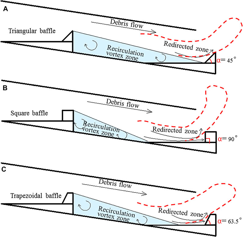
FIGURE 10. Sketch of the flow structure of debris flows passing over (A) triangular (B) square and (C) trapezoidal baffles.
In step-baffle drainage channels, the magnitude of energy dissipation decreases from the trapezoidal baffles to the square baffles with the lowest being the triangular baffles (see Figure 8). We attempt to explain these results using generalized diagrams of the flow structure in step-baffle systems, as illustrated in Figure 10. The debris flow structure between the adjacent step-baffles is divided into two regions: the recirculation vortex zone characterized by eddies and vortices and the redirected zone that re-adjusts the flow toward the main flow. The energy dissipation mainly occurs in two regions. However, the recirculation vortex zone plays a minimal role in dissipating energy, while the redirected zone dissipates considerable energy, especially for skimming debris flow. The energy dissipation for the redirected zone depends mainly on the momentum transfer. Among the reasons why square baffles dissipate more energy than the triangular baffles is that the area of the redirected zone is greater for the square baffle configuration. Although, the area of the redirected zone for square baffles (Figure 10A) is larger than that of trapezoidal baffles (Figures 10B,C), the influence of the baffle shape (90° of upwind stream face) in adjusting the flow toward the main flow is too strong and instead propels the debris high into the air. These will result in high additional potential energy which later contributes to the increase in momentum, compensating for the reduction in energy.
The effectiveness of the step-baffle drainage channel to regulate the solid phase in debris flows can be ranked according to trapezoidal, square, and triangular baffles (see Figure 7D). The trapezoidal baffles experience greater impact forces than triangular baffles, and at least for the first baffle in the channel, it is the square baffles that experience the greatest impact force (see Figure 9). In other words, in a step channel with square baffles, it is the first baffle that will most likely be damaged by the debris flow impact, while it is the second baffle in both triangular and trapezoidal baffles that are likely to be destroyed by debris flow impacts.
In practice, it is difficult to guarantee that all the evaluation indices of any type of baffle are optimal at the same time. It is recommended that for a specific creek valley, field surveys and measurements of the topography, scale, and velocity of possible debris flow events should be conducted in advance from which suitable types of drainage channels can be designed.
In this study, the flume model is adopted to study the mitigation of step-baffle drainage channels on debris flows. A series of tests with varying source material densities and baffle shapes (triangular, trapezoidal, and square) are carried out to demonstrate the performance of each baffle type in terms of the induced flow pattern, sediment transportation, energy dissipation, and impact pressure. The conclusions are summarized as follows:
1) The flow pattern in the step-baffle drainage channel is a very complex wave-like flow. The lifting height of debris flows induced by square baffles is the largest, whereas the lowest lifting heights are recorded for trapezoidal baffles.
2) Trapezoidal baffle systems trap the largest volume of sediments whereas triangular baffles trap the least. Similarly, trapezoidal baffles also dissipate the most energy while the triangular baffles dissipate the least.
3) The impact forces experienced by trapezoidal baffles are larger than those of triangular baffles. The impact on the first baffle in square systems is the largest among the three geometries under similar flow conditions, while the impact pressure on the second baffle of both triangular and trapezoidal baffle systems is greater than that on square baffles. The results give insight into potential strategies for designing debris-resisting barriers in debris flow drainage channels.
The original contributions presented in the study are included in the article/Supplementary Material; further inquiries can be directed to the corresponding author.
SL and XC made substantial contributions to the conception, validation, project administration, and funding acquisition. JC and YY made substantial contributions to the methodology, supervision, and writing—original draft preparation. HC and WZ made substantial contributions to the resources, data curation, and investigation. HT made substantial contributions to reviewing and editing. XG polished the English, reviewed the results and approved the manuscript.
The authors declare that the research was conducted in the absence of any commercial or financial relationships that could be construed as a potential conflict of interest.
All claims expressed in this article are solely those of the authors and do not necessarily represent those of their affiliated organizations, or those of the publisher, the editors, and the reviewers. Any product that may be evaluated in this article, or claim that may be made by its manufacturer, is not guaranteed or endorsed by the publisher.
The authors would like to thank the funding supported by the National Natural Science Foundation of China (Grant Nos. 42007270 and 41925030), the Strategic Priority Research Program of the Chinese Academy of Sciences (Grant No. XDA23090403), the Sichuan Science and Technology Program (Grant No. 2019YJ0009), the Youth Innovation Promotion Association CAS (Grant No. 2022379), and the Helmholtz-OCPC Postdoc Program fellowship (ZD2019042).
Abrahams, A. D., Li, G., and Atkinson, J. F. (1995). Step-pool Streams: Adjustment to Maximum Flow Resistance. Water Resour. Res. 31 (10), 2593–2602. doi:10.1029/95wr01957
Armanini, A., Larcher, M., and Odorizzi, M. (2011). “Dynamic Impact of a Debris Flow Front against a Vertical Wall,” in Proceedings of the 5th International Conference on Debris-Flow Hazards, Mitigation, Mechanics, Prediction and Assessment, Padua, Italy (Rome: Casa Editrice Universita` La Sapienza), 1041–1049.
Bernard, M., Boreggio, M., Degetto, M., and Gregoretti, C. (2019). Model-based approach for design and performance evaluation of works controlling stony debris flows with an application to a case study at Rovina di Cancia (Venetian Dolomites, Northeast Italy). Sci. total Environ. 688, 1373–1388. doi:10.1016/j.scitotenv.2019.05.468
Bung, D. B., Sun, Q., Meireles, I., Viseu, T., and Matos, J. S. (2012). “USBR Type III Stilling Basin Performance for Steep Stepped Spillways,” in Proc. 4th Intl. IAHR Symposium on Hydraulic Structures. Editors J. Matos, S. Pagliara, and I. Meireles. (Porto, Portugal: Portuguese Water Resources Association). (CD-ROM).
Chanson, H. (2001). The Hydraulics of Stepped Chutes and Spillways. Lisse, the Netherlands: Balkema Publishers.
Chartrand, S. M., and Whiting, P. J. (2000). Alluvial Architecture in Headwater Streams with Special Emphasis on Step-Pool Topography. Earth Surf. Process. Landforms 25 (6), 583–600. doi:10.1002/1096-9837(200006)25:6<583::aid-esp92>3.0.co;2-3
Chen, J.-G., Chen, X.-Q., Chen, H.-Y., and Zhao, W.-Y. (2016). Characteristics of Viscous Debris Flow in a Drainage Channel with an Energy Dissipation Structure. J. Mt. Sci. 13 (2), 223–233. doi:10.1007/s11629-014-3290-z
Chen, J., Chen, X., Li, Y., and Wang, F. (2015). An Experimental Study of Dilute Debris Flow Characteristics in a Drainage Channel with an Energy Dissipation Structure. Eng. Geol. 193, 224–230. doi:10.1016/j.enggeo.2015.05.004
Chen, J., Chen, X., Zhao, W., and You, Y. (2018). Debris Flow Drainage Channel with Energy Dissipation Structures: Experimental Study and Engineering Application. J. Hydraul. Eng. 144 (10), 06018012. doi:10.1061/(asce)hy.1943-7900.0001523
Chen, J., Chen, X., Zhao, W., Yu, X., and Wang, X. (2017). Experimental Study on the Characteristics of a Debris-Flow Drainage Channel with an Energy Dissipation Structure. Bull. Eng. Geol. Environ. 76 (1), 341–351. doi:10.1007/s10064-016-0860-z
Chen, X.-q., You, Y., Chen, J.-g., Huang, K., and Li, D.-j. (2014). Characteristics of a Drainage Channel with Staggered Indented Sills for Controlling Debris Flows. J. Mt. Sci. 11 (5), 1242–1252. doi:10.1007/s11629-013-2917-9
Chen, X., Chen, J., Zhao, W., Li, Y., and You, Y. (2017). Characteristics of a Debris-Flow Drainage Channel with a Step-Pool Configuration. J. Hydraul. Eng. 143 (9), 04017038. doi:10.1061/(asce)hy.1943-7900.0001352
Chen, X., Cui, P., You, Y., Chen, J., and Li, D. (2015). Engineering Measures for Debris Flow Hazard Mitigation in the Wenchuan Earthquake Area. Eng. Geol. 194, 73–85. doi:10.1016/j.enggeo.2014.10.002
Chin, A. (1999). The Morphologic Structure of Step–Pools in Mountain Streams. Geomorphology 27 (3-4), 191–204. doi:10.1016/s0169-555x(98)00083-x
Chin, A. (2002). The Periodic Nature of Step-Pool Mountain Streams. Am. J. Sci. 302 (2), 144–167. doi:10.2475/ajs.302.2.144
Choi, C. E., Ng, C. W. W., Law, R. P. H., Song, D., Kwan, J. S. H., and Ho, K. K. S. (2015). Computational Investigation of Baffle Configuration on Impedance of Channelized Debris Flow. Can. Geotech. J. 52 (2), 182–197. doi:10.1139/cgj-2013-0157
Comiti, F., Cadol, D., and Wohl, E. (2009). Flow Regimes, Bed Morphology, and Flow Resistance in Self-Formed Step-Pool Channels. Water Resour. Res. 45 (4), 1–18. doi:10.1029/2008wr007259
Cui, P., Zeng, C., and Lei, Y. (2015). Experimental Analysis on the Impact Force of Viscous Debris Flow. Earth Surf. Process. Landforms 40 (12), 1644–1655. doi:10.1002/esp.3744
Cui, P., Zhuang, J. Q., Chen, X. C., Zhang, J. Q., and Zhou, X. J. (2010). Characteristics and Countermeasures of Debris Flow in Wenchuan Area after the Earthquake. J. Sichuan Univ. Eng. Sci. Ed. 42 (5), 10–19. (In Chinese). doi:10.15961/j.jsuese.2010.05.004
Felder, S., Geuzaine, M., Dewals, B., and Erpicum, S. (2019). Nappe Flows on a Stepped Chute with Prototype-Scale Steps Height: Observations of Flow Patterns, Air-Water Flow Properties, Energy Dissipation and Dissolved Oxygen. J. Hydro-environment Res. 27, 1–19. doi:10.1016/j.jher.2019.07.004
Golly, A., Turowski, J. M., Badoux, A., and Hovius, N. (2019). Testing Models of Step Formation against Observations of Channel Steps in a Steep Mountain Stream. Earth Surf. Process. Landforms 44 (7), 1390–1406. doi:10.1002/esp.4582
Huang, H., Ma, D. T., and Wang, X. L. (2009). Experimental Study on the Relationship between the Velocity of Debris Flow and Structure of the Dongchuan Debris Flow Channel. J. Mt. Sci. 27 (5), 551–556. (In Chinese).
Hübl, J., Suda, J., and Proske, D. (2009). “Debris Flow Impact Estimation,” in the 11th international symposium on water management and hydraulic engineering conference. Ohrid, Macedonia: University of Ss Cyril and Methodius, Faculty of Civil Engineering, Skopje, Macedonia, 1–4.
Iverson, R. M. (2015). Scaling and Design of Landslide and Debris-Flow Experiments. Geomorphology 244, 9–20. doi:10.1016/j.geomorph.2015.02.033
Li, D. J. (1997). Debris Flow Mitigation Theory and Practices. Beijing: Science Press, 132–148. (In Chinese).
Li, S., Peng, C., Wu, W., Wang, S., Chen, X., Chen, J., et al. (2020). Role of Baffle Shape on Debris Flow Impact in Step-Pool Channel: an SPH Study. Landslides 17, 2099–2111. doi:10.1007/s10346-020-01410-w
Marchi, L., Comiti, F., Crema, S., and Cavalli, M. (2019). Channel Control Works and Sediment Connectivity in the European Alps. Sci. total Environ. 668, 389–399. doi:10.1016/j.scitotenv.2019.02.416
Matos, J., and Chanson, H. (2006). “Hydraulic Structures: a Challenge to Engineers and Researchers,” in Proceedings of the International Junior Researcher and Engineer Workshop on Hydraulic Structures (IJREWHS’06) (Montemor-o-Novo: Division of Civil Engineering, University of Queensland. Hydraulic Model Report No. CH61/06, Div. of Civil Engineering.
Ozturk, U., Wendi, D., Crisologo, I., Riemer, A., Agarwal, A., Vogel, K., et al. (2018). Rare Flash Floods and Debris Flows in Southern Germany. Sci. total Environ. 626, 941–952. doi:10.1016/j.scitotenv.2018.01.172
Saletti, M., and Hassan, M. A. (2020). Width Variations Control the Development of Grain Structuring in Steep Step‐pool Dominated Streams: Insight from Flume Experiments. Earth Surf. Process. Landforms 45 (6), 1430–1440. doi:10.1002/esp.4815
VanDine, D. F. (1996). Debris Flow Control Structures for Forest Engineering. Victoria, B.C.: Research Branch, B.C. Ministry of Forests. (Working Paper 08/1996).
Wang, F., Chen, X., Chen, J., and You, Y. (2017). Experimental Study on a Debris-Flow Drainage Channel with Different Types of Energy Dissipation Baffles. Eng. Geol. 220, 43–51. doi:10.1016/j.enggeo.2017.01.014
Wang, T., Chen, X., Li, K., Chen, J., and You, Y. (2018). Experimental Study of Viscous Debris Flow Characteristics in Drainage Channel with Oblique Symmetrical Sills. Eng. Geol. 233, 55–62. doi:10.1016/j.enggeo.2017.11.024
Wang, Z. Y., Qi, L., and Wang, X. (2012). A Prototype Experiment of Debris Flow Control with Energy Dissipation Structures. Nat. Hazards 60 (3), 971–989. doi:10.1007/s11069-011-9878-5
Wilcox, A. C., Wohl, E. E., Comiti, F., and Mao, L. (2011). Hydraulics, Morphology, and Energy Dissipation in an Alpine Step-Pool Channel. Water Resour. Res. 47 (7), W07514. doi:10.1029/2010WR010192
Wooldridge, C. L., and Hickin, E. J. (2002). Step-pool and Cascade Morphology, Mosquito Creek, British Columbia: a Test of Four Analytical Techniques. Can. J. Earth Sci. 39 (4), 493–503. doi:10.1139/e01-087
You, Y., and Liu, J. F. (2008). The Optimum Cross-Section Design on the V-Shaped Drainage Channel of Debris Flow. J. Mt. Sci. 26 (2), 218–222. (In Chinese)
You, Y., Pan, H., Liu, J., and Ou, G. (2011). The Optimal Cross-Section Design of the “Trapezoid-V” Shaped Drainage Canal of Viscous Debris Flow. J. Mt. Sci. 8 (1), 103–107. doi:10.1007/s11629-011-1023-0
Zhang, C., Xu, M., Hassan, M. A., Chartrand, S. M., Wang, Z., and Ma, Z. (2019). Experiment on Morphological and Hydraulic Adjustments of Step‐pool Unit to Flow Increase. Earth Surf. Process. Landforms 45, 280–294. doi:10.1002/esp.4722
Zhou, G. G. D., and Ng, C. W. W. (2010). Dimensional Analysis of Natural Debris Flows. Can. Geotech. J. 47 (7), 719–729. doi:10.1139/t09-134
Keywords: drainage channel, debris flow, flume test, energy dissipation, impact-resisting
Citation: Li S, Chen X, Chen J, Tang H, You Y, Chen H, Zhao W and Geng X (2022) Small-Scale Flume Investigation of the Performance of Step-Baffle Drainage Channels in Mitigating Debris Flows. Front. Earth Sci. 10:921716. doi: 10.3389/feart.2022.921716
Received: 16 April 2022; Accepted: 30 May 2022;
Published: 06 July 2022.
Edited by:
Wen Zhang, Jilin University, ChinaReviewed by:
Xinghua Zhu, Chang’an University, ChinaCopyright © 2022 Li, Chen, Chen, Tang, You, Chen, Zhao and Geng. This is an open-access article distributed under the terms of the Creative Commons Attribution License (CC BY). The use, distribution or reproduction in other forums is permitted, provided the original author(s) and the copyright owner(s) are credited and that the original publication in this journal is cited, in accordance with accepted academic practice. No use, distribution or reproduction is permitted which does not comply with these terms.
*Correspondence: Jiangang Chen, Y2hlbmpnQGltZGUuYWMuY24=
Disclaimer: All claims expressed in this article are solely those of the authors and do not necessarily represent those of their affiliated organizations, or those of the publisher, the editors and the reviewers. Any product that may be evaluated in this article or claim that may be made by its manufacturer is not guaranteed or endorsed by the publisher.
Research integrity at Frontiers

Learn more about the work of our research integrity team to safeguard the quality of each article we publish.