 Feng Chen
 Xue-Bin Wang2
95% of researchers rate our articles as excellent or good
Learn more about the work of our research integrity team to safeguard the quality of each article we publish.
Find out more
ORIGINAL RESEARCH article
Front. Earth Sci. , 11 May 2022
Sec. Geohazards and Georisks
Volume 10 - 2022 | https://doi.org/10.3389/feart.2022.899755
This article is part of the Research Topic Rock Landslide Risk Assessment, Stability Analysis and Monitoring for The Development of Early Warning Systems and Reinforcement Measures View all 24 articles
With the continuous increase in the mining depth and engineering burying depth, the nonlinear physical and mechanical phenomena exhibited by rock are more complicated. The load value often exceeds the yield strength of the traditional Poisson’s ratio support materials, resulting in failure of the support body. Therefore, the bolt still needs further in-depth research into new materials. In this study, the numerical model with a negative Poisson’s ratio bolt had been established, the properties of negative Poisson’s ratio materials and the working principle of RFPA software were introduced, and RFPA software was used to study the reinforcement effect of negative Poisson’s ratio bolt on the rock. The numerical experiment results show that compared with the positive Poisson’s ratio bolt, the negative Poisson’s ratio bolt can significantly increase the bearing capacity of anchored rock; enhance the friction between the bolt, body, and the surrounding rock; and limit the rock movement. The anchored rock with a negative Poisson’s ratio bolt can absorb more energy. A negative Poisson’s ratio material is one of the future development directions of the bolt material.
A bolt is a kind of support body that transmits the tensile load to the stable rock layer to improve the stability and strength of the rock medium, and has a lower cost in terms of material and manpower, so it has been widely used in mining, transportation, water conservancy, and urban underground space engineering (He et al., 2005; Hyett et al., 2015; Vandermaat et al., 2016; Kim et al., 2017). With the development of rock anchoring, problems in the direction of “large, deep, and difficult” sudden engineering disasters and major malignant accidents caused by nonlinear large deformation damage have occurred frequently in recent years (He et al., 2005). The reason for these problems is that the traditional supporting materials including traditional bolts, anchor cables, U-shaped steel brackets, and other traditional supporting materials frequently fail (Jalalifar, 2006; Kang et al., 2013). One of the root causes is that the materials of these supporting bodies belong to the traditional Poisson’s ratio materials, that is, plastic hardening materials, which instantly reach the yield strength and lose the bearing capacity under a large load, leading to the failure of the support (Wan et al., 2004; Alderson and Alderson, 2007; He et al., 2014; Yu et al., 2016).
Poisson’s ratio ν is called the transverse deformation coefficient, which refers to the value of the ratio changed in the sign of the transverse strain to the axial normal strain when the material is subjected to uniaxial tension or compression. It is the elastic constant reflecting the material transverse deformation and is expressed by the formula as
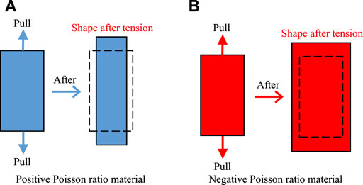
FIGURE 1. Deformation of axial tension material. (A)Positive Poisson ratio material. (B) Negative Poisson ratio material.
According to the thermodynamic theory, Poisson’s ratio of isotropic material ranges from −1 to 1, so there are negative Poisson’s ratio materials in theory (Horrigan et al., 2009; Gaspar, 2010). Lakes was the first to obtain a new type of material of a concave unit structure with a Poisson’s ratio −0.7 in a series of treatments of ordinary polyurethane foam in 1987 (Shi et al., 2012). This also means that when the material is subjected to axial tension, it will cause lateral expansion deformation (see Figure 1B). This kind of auxetic behavior greatly improves the material mechanical properties such as shear modulus, fracture toughness, energy absorption, and indentation resistance. In addition, negative Poisson’s ratio materials have a good stress dispersion effect, a very high shear modulus, and a very low bulk modulus (Evans, 2010; Liu and Hu, 2010; Critchley et al., 2013; Saxena et al., 2016). Because negative Poisson’s ratio materials have a higher value of the strength than positive Poisson’s ratio materials, they can be used as structural materials and functional materials at the same time. Therefore, they have broad application space in the fields of biomedicine and national defense technology (Lakes, 1987; Martz et al., 1996; Li et al., 2019).
Because the physical and mechanical parameters of different experimental samples have a certain degree of discreteness, it is impossible to change only one physical and mechanical parameter of the experimental sample while keeping other physical and mechanical parameters the same in indoor and outdoor comparative experiments (Tang et al., 2018; Chen et al., 2019). However, the numerical experiment method can quickly adjust the parameters.
Based on the special mechanical properties of negative Poisson’s ratio material, as well as the advantages of the numerical experiment method, we used RFPA2D-Basic software to study the failure characteristics of an anchored rock with a negative Poisson’s ratio bolt. The similarities and differences in stress, displacement, and acoustic emission (AE) of anchored rocks with the positive Poisson’s ratio bolt and the negative Poisson’s ratio bolt had been compared and analyzed.
Since Lakes (1987) first pointed out that a material with a cellular structure can produce a negative Poisson’s ratio during deformation, a large number of negative Poisson’s ratio materials and structures have been discovered, synthesized, and prepared, ranging from a molecular microscopic scale to macrostructure scale (Grima et al., 2005; Alderson et al., 1998; Ravirala et al., 2006; Alderson et al., 2002; Lakes, 1993). Figure 2 shows negative Poisson’s ratio materials at different scale levels. The structure of negative Poisson’s ratio materials is also diverse, including negative Poisson’s ratio foam structure, microscopic negative Poisson’s ratio structure, and negative Poisson’s ratio composite structure (Wojciechowski, 1989; Grima et al., 2006; Gercek, 2007; Miller et al., 2009).
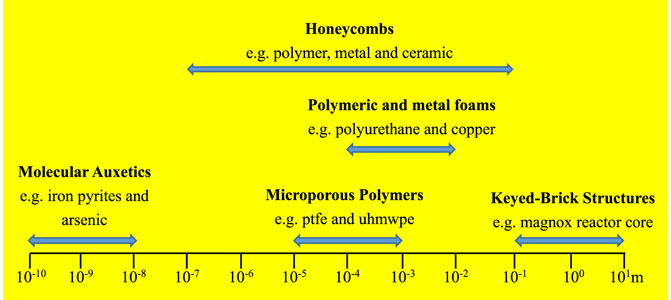
FIGURE 2. Different scale materials with negative Poisson’s ratio.
Negative Poisson’s ratio material can improve the service performance of the structure by designing the mechanical properties of the structure (Alderson et al., 2002; Grima et al., 2006). The elastic properties of the material can be expressed by four elastic constants in elastic theory, namely, Young’s modulus E, shear modulus G, bulk modulus K, and Poisson’s ratio ν. These four constants are not independent of each other for the isotropic material, and they are related to each other by the following equation: G= E/(2(1+ν)) and K= E/(3(1-2ν))。. Many materials require G to be larger than K. If we change ν by changing the microstructure of the material under the condition that the E of the material remains unchanged, we can change the values of K and G. For example, when ν is reduced to −1, a shear modulus that is much higher than a bulk modulus can be obtained. In other words, the material is not prone to shear deformation but prone to volume changes.
Tang et al. (1998) proposed a new numerical simulation software named RFPA (Realistic Failure Process Analysis). RFPA software is a numerical experiment tool that can simulate the progressive failure process of the material. The calculation method of this software is based on finite element theory and statistical damage theory. This method has considered the nonuniformity of material properties and the randomness of defect distribution and combined the statistical distribution assumptions of this material property into the numerical calculation method (finite element method). The elements which satisfy the given strength criterion are destroyed, so that the numerical simulation of the failure process of heterogeneous materials can be realized (Li and Tang, 2015; Huang et al., 2017; Li et al., 2018; Tang et al., 2020).
The entire workflow can be seen in Figure 3. For each given displacement increment, RFPA software first performs stress calculation and then checks whether there are phase change primitives in the model according to the phase change criterion. If there is no phase change element, this software will continue loading to add a displacement component and proceed to the next step of stress calculation (Tang, 1997; Tang and Kaiser, 1998; Tang, 2003). If there is a phase change element, the stiffness will be weakened according to the stress state of the element, and then the stress calculation of the current step is performed again until no new phase change element appears. The aforementioned process is repeated until the applied load, deformation, or macro fracture of the whole medium is reached (Zhang et al., 2007; Du et al., 2019; Du et al., 2021).
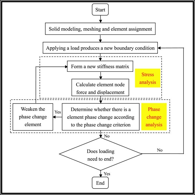
FIGURE 3. RFPA software workflow picture.
In order to study the negative Poisson’s ratio effect of the bolt, a numerical model has been established (see Figure 4). The one-dimensional coordinate system is established along the axial direction of the bolt for the convenience of marking, and the origin O of the coordinate is located on the upper side of the bolt. The overall size of the model is 2000 × 1,500 mm, and the number of divided units is 400 × 300. The bottom side of this numerical model is fixed. Displacement compression load is applied to the left and right sides of the model, and the displacement increment is 0.002 mm. The tensile load is applied to the upper-end face of the bolt, and the displacement increment is also 0.002 mm. The bolt size is 1,000 × 20 mm, which is located in the transverse middle of this model. Three points A, B, and C are marked along the left boundary of the bolt to analyze the lateral displacement of the rock. The coordinates of the aforementioned three points along the axial direction of the bolt are 250 mm, 500, and 750 mm, respectively. The physical and mechanical parameters of rock mass and bolt are shown in Table 1. At the same time, the numerical model of the bolt with a positive Poisson’s ratio is established. The Poisson’s ratio of the bolt with a positive Poisson’s ratio is 0.3, and the other physical and mechanical parameters are the same as that of the bolt with a negative Poisson’s ratio. The constitutive relation of the rock bolt is simplified as an elastic-plastic model, and the rock is endowed with an ideal elastic-plastic constitutive relation. The anchoring effects of two kinds of bolts are compared and analyzed.
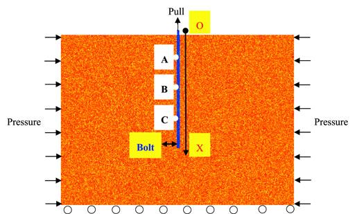
FIGURE 4. Numerical model.
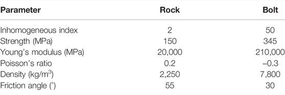
TABLE 1. Physical and mechanical parameters of the rock and the bolt with a positive Poisson’s ratio.
As shown in Figure 5, the displacements of points A, B, and C of anchored rock with the negative Poisson’s ratio bolt all increase linearly under the action of external force, the slopes of displacement curves are the same. The displacement values of the three points are 1.4293, 1.4018, and 1.4063 mm, respectively, after the negative Poisson’s ratio bolt is broken. Under the action of external force, the displacements of points A, B, and C of the anchored rock with the positive Poisson’s ratio bolt also show a linear increase and the changing trend of displacement curves is the same. The displacement values of the three points are 0.4219, 0.4221, and 0.4211 mm, respectively, after the positive Poisson’s ratio bolt is broken. Because the anchored rock with the positive Poisson’s ratio bolt ends the numerical experiment in loading step 168, the horizontal coordinates of the displacement and stress comparison curves of two anchored rocks are taken to loading step 168. The displacements of points A, B, and C of anchored rock with the positive Poisson’s ratio bolt are greater than those of anchored rock with the negative Poisson’s ratio bolt at any loading moment. This is because the positive Poisson’s ratio material undergoes lateral contraction deformation, the surrounding rock can further deform toward the bolt body, while the negative Poisson’s ratio material undergoes lateral expansion deformation, which limits the deformation of the surrounding rock to the bolt body and reduces the displacement of surrounding rock. The aforementioned numerical experiment results are in line with the actual situation, indicating that it is feasible and reliable to use numerical experimental methods to study this problem. In addition, the displacement differences of points A, B, and C generally increase linearly, the maximum displacement differences of the aforementioned three points are 0.0015, 0.0028, and 0.0012 mm (see Figure 6).
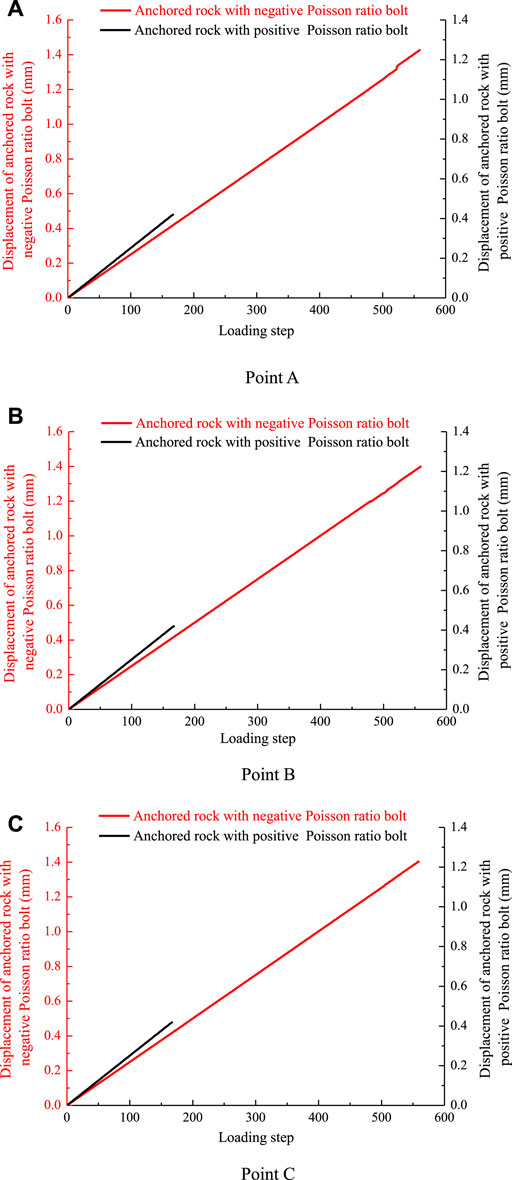
FIGURE 5. Displacement comparison curves of points A, B, and C of two kinds of anchored rock. (A) Point A. (B) Point B. (C) Point C.
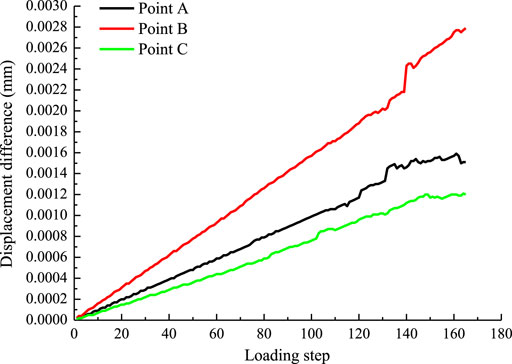
FIGURE 6. Displacement difference curve of points A, B, and C of two kinds of anchored rock.
It can be seen from Figure 7 that the bearing capacity of anchored rock with the negative Poisson’s ratio bolt reaches the maximum value of 378.2 MPa in loading step 479, this bolt is not damaged at this time (see Figure 8A). When loading continues, the bearing capacity begins to drop, and then the bolt first breaks in the middle of the bolt body at loading step 480 (see Figure 8B).
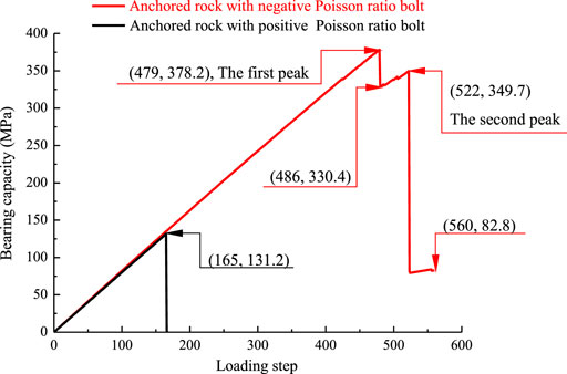
FIGURE 7. Stress curve of two different anchored rocks.
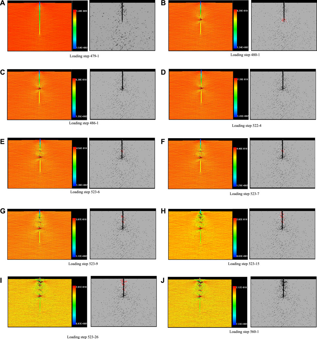
FIGURE 8. Failure process of anchored rock with the negative Poisson’s ratio bolt (the left column is the minimum principal stress nephogram, and the right column is the acoustic emission diagram). (A) Loading step 479-1. (B) Loading step 480-1. (C) Loading step 486-1. (D) Loading step 522-4. (E) Loading step 523-6. (F) Loading step 523-7. (G) Loading step 523-9. (H) Loading step 523-15. (I) Loading step 523-26. (J) Loading step 560-1.
The bearing capacity drops to 330.4 MPa in the 486th step. Then the bearing capacity increases slightly and reaches the second peak of 349.7 MPa. The other parts of the bolt body are not damaged at this stage (see Figures 8C∼D). At the next loading step when the stress reaches the second peak, i.e., loading step 523, the failure occurs successively at 5/8, 6/8, and 7/8 positions of the bolt body (see Figures 8E∼I). Through the aforementioned analysis, it can be seen that the failure of the bolt body occurs in the next loading step after the stress reaches the peak value, which is also the stage of stress decrease. On the other hand, there is only one failure in the anchored rock mass with the positive Poisson’s ratio bolt (see Figure 9).
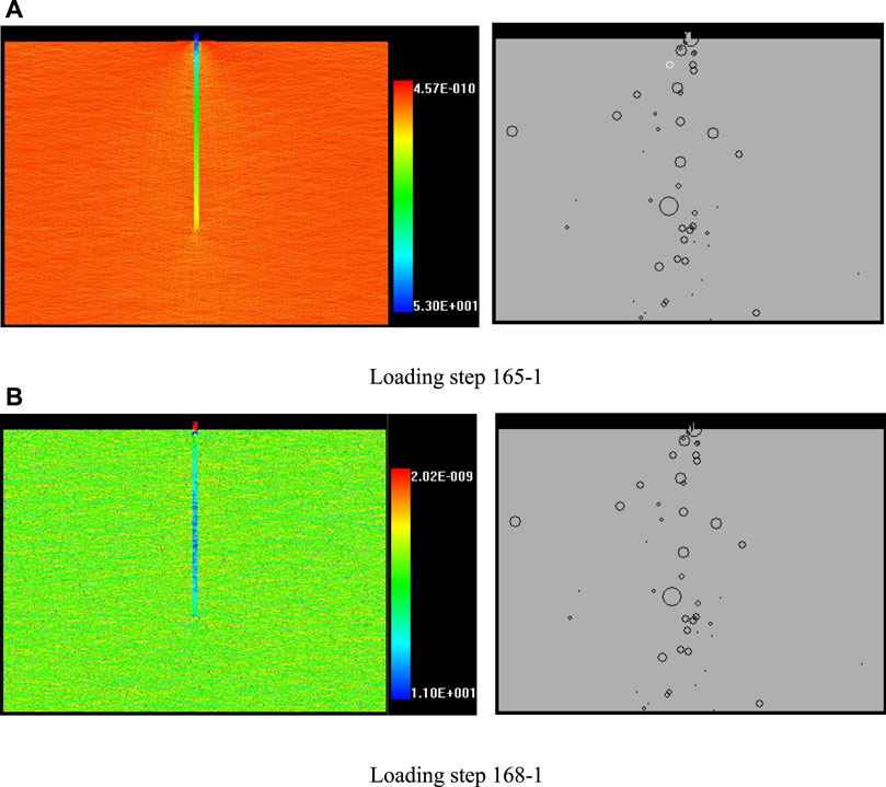
FIGURE 9. Failure process of anchored rock with the positive Poisson’s ratio bolt (the left column is the minimum principal stress nephogram, and the right column is the acoustic emission diagram). (A) Loading step 165-1. (B) Loading step 168-1.
When the loading is over, the bearing capacity of the rock strengthened by the positive Poisson’s ratio bolt is reduced to 0, while the rock strengthened by the negative Poisson’s ratio bolt still has a certain bearing capacity, which is 82.8 MPa. The maximum bearing capacity of the rock reinforced with positive and negative Poisson’s ratio bolts is 131.2 and 378.2 MPa, respectively. It can be seen that the addition of a negative Poisson’s ratio bolt in the rock can improve the stress state of the rock mass, enhance the bearing capacity of the anchored rock mass, and make up for the defects of the traditional bolt.
As shown in Figure 10, the stress of points A, B, and C of the anchored rock with the negative Poisson’s ratio bolt is greater than that of the corresponding points of anchored rock with the positive Poisson’s ratio bolt. This is because the expansion deformation of the bolt body increases the friction between the bolt body and the surrounding rock, and the increased friction in turn also limits the displacement of the surrounding rock.
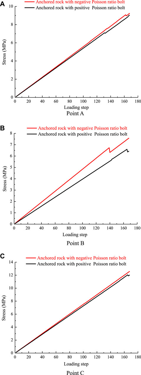
FIGURE 10. Stress comparison curves of points A, B, and C of two kinds of anchored rock before loading step 168. (A) Point A. (B) Point B. (C) Point C.
When it is loaded to loading step 480, both AE quantity and AE energy of the anchored rock mass with the negative Poisson’s ratio bolt appear to rise suddenly, reaching the first peak value, and their values are 145 times and 0.099 J, respectively (see Figure 11 and Figure 12). When it is loaded to loading step 523, the number and energy of AE increase again, reaching the second peak value, which is 296 time and 0.403 J, respectively. The difference is that the second peak value of stress is lower than the first peak value, while the second peak value of AE quantity and AE energy are both higher than the first peak. This also shows that the AE quantity and AE energy mainly occur in the stress drop stage. The number of AE quantity reaches the peak value for the anchored rock with the positive Poisson’s ratio bolt when loaded to loading step 166 (see Figure 13). The peak of AE quantity is also after the stress peak, but the AE energy does not show obvious regularity (see Figure 14).
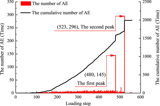
FIGURE 11. AE curve of anchored rock with the negative Poisson’s ratio bolt.
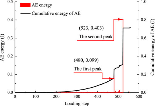
FIGURE 12. AE energy curve of anchored rock with the negative Poisson’s ratio bolt.
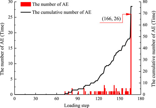
FIGURE 13. AE curve of anchored rock with the positive Poisson’s ratio bolt.
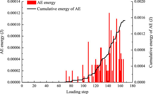
FIGURE 14. AE energy curve of anchored rock with the positive Poisson’s ratio bolt.
It can be seen from Table 2 that the maximum and cumulative values of AE energy of the anchored rock mass with the positive Poisson’s ratio bolt are 0.00012 and 0.00153 J, respectively. The maximum and cumulative value of AE energy of anchored rock with the negative Poisson’s ratio are much larger than that of anchored rock with the negative Poisson’s ratio, and the values are 0.40329 and 0.71482 J, respectively. The aforementioned phenomena show that more energy would be absorbed after the negative Poisson’s ratio bolt is driven into the rock. That is to say, after adding a negative Poisson’s ratio bolt to rock, the negative Poisson’s ratio bolt can better protect the integrity of the surrounding rock and prevent the occurrence of geological disasters under the condition of the same geological conditions and load.
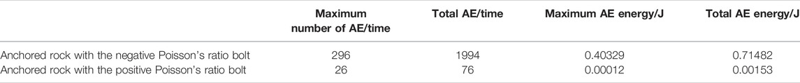
TABLE 2. Number and energy of AE in two different anchored rocks after loading.
Mogi (1985) summarized three basic types of AE by analyzing the AE characteristics of different types of materials, namely, main shock type, foreshock–main shock–aftershock type, and swarm shock type. According to this AE classification basis, it can be known that the AE quantity and AE energy for the anchored rock with the negative Poisson’s ratio bolt belong to the main shock type, while the AE quantity and AE energy of the anchored rock with the positive Poisson’s ratio bolt belong to the main shock type and the swarm shock type, respectively.
(1) Under the action of external force, the expansion deformation of the negative Poisson’s ratio bolt prevents the surrounding rock from moving toward the bolt, causing the displacement of the surrounding rock around the bolt with the negative Poisson’s ratio to be smaller than that around the bolt with the positive Poisson’s ratio. The numerical experiment results are in good agreement with the actual situation, which also proves the reliability of the numerical experiment.
(2) The negative Poisson’s ratio bolt has been damaged sequentially from one half of the bolt body to the bolt head under the stress of surrounding rock, the failure mode of rock mass near the bolt failure is a tensile failure, and the bolt failure occurs in the stage of stress reduction. When the bolt Poisson’s ratio changes from positive to negative, the bearing capacity of anchored mass rock is greatly increased, and the maximum bearing capacity is increased by 2.9 times. The anchored rock with the negative Poisson’s ratio bolt still has a certain residual bearing capacity value after loading, which increases the strength of the reinforced body. The surrounding rock stress of the negative Poisson’s ratio bolt is higher than the surrounding rock stress of the positive Poisson’s ratio bolt, which means that the friction between the bolt and the surrounding rock has been increased, the movement of the surrounding rock has been restricted, and the integrity of surrounding rock has been protected.
(3) The peak values of AE quantity and AE energy of anchored rock with the negative Poisson’s ratio bolt occur in the next loading step of the peak bearing capacity. The maximum loadable energy and cumulative energy of anchored rock with the negative Poisson’s ratio bolt are far greater than that of anchored rock with the positive Poisson’s ratio bolt, indicating that the reinforcement body with a negative Poisson’s ratio bolt can absorb more energy and increase the strength and stiffness of anchored rock. In addition, the AE quantity and AE energy of the anchored rock with the negative Poisson’s ratio bolt belong to the main shock type, and the AE quantity and AE energy of the anchored rock with the positive Poisson’s ratio bolt belong to the main shock type and the swarm shock type, respectively.
The raw data supporting the conclusion of this article will be made available by the authors, without undue reservation.
FC: data curation and manuscript writing; X-BW: supervision; Y-HD: conceptualization; and C-AT: software.
This study was supported by the Chinese National Natural Science Foundation (No. 52074142).
The authors declare that the research was conducted in the absence of any commercial or financial relationships that could be construed as a potential conflict of interest.
All claims expressed in this article are solely those of the authors and do not necessarily represent those of their affiliated organizations, or those of the publisher, the editors, and the reviewers. Any product that may be evaluated in this article, or claim that may be made by its manufacturer, is not guaranteed or endorsed by the publisher.
Alderson, A., and Alderson, K. L. (2007). Auxetic Materials. Proc. Institution Mech. Eng. Part G J. Aerosp. Eng. 221, 565–575. doi:10.1243/09544100jaero185
Alderson, K. L., Alderson, A., Webber, R. S., and Evans, E. (1998). Evidence for Uniaxial Drawing in the Fibrillated Microstructure of Auxetic Microporous Polymers[J]. J. Mater. Sci. 17 (16), 1415–1419. doi:10.1023/a:1026409404057
Alderson, K. L., Alderson, A., Smart, G., Simkins, V. R., and Davies, P. J. (2002). Auxetic Polypropylene fibres:Part 1 - Manufacture and Characterisation. Plastics, Rubber Compos. 31 (8), 344–349. doi:10.1179/146580102225006495
Chen, F., Tang, C. A., Sun, X. M., Ma, T. H., and Du, Y. H. (2019). Supporting Characteristics Analysis of Constant Resistance Bolts under Coupled Static-Dynamic Loading[J]. J. Mt. Sci. 16 (05), 217–226. doi:10.1007/s11629-018-5044-9
Critchley, R., Corni, I., Wharton, J. A., Walsh, F. C., Wood, R. J. K., and Stokes, K. R. (2013). A Review of the Manufacture, Mechanical Properties and Potential Applications of Auxetic Foams. Phys. Status Solidi B 250 (10), 1963–1982. doi:10.1002/pssb.201248550
Du, Y., Xie, M. W., Jiang, Y. J., Liu, W. N., Liu, R. C., and Liu, Q. Q. (2019). Research Progress on Dynamic Monitoring Index for Early Warning of Rock Collapse [J]. Chin. J. Eng. 41 (04), 427–435. doi:10.13374/j.issn2095-9389.2019.04.002
Du, Y., Xie, M. W., Jiang, Y. J., Chen, C., Jia, B. N., and Huo, L. C. (2021). Review on the Formation Mechanism and Early Warning of Rock Collapse[J]. Metal. Mine 535 (01), 106–119. doi:10.19614/j.cnki.jsks.202101008
Evans, K. E. (2010). Auxetic Materials: Functional Materials and Structures from Lateral Thinking. J. Adv. Mater. 12 (9), 617–628.
Gaspar, N. (2010). A Granular Material with a Negative Poisson's Ratio. Mech. Mater. 42, 673–677. doi:10.1016/j.mechmat.2010.05.001
Gercek, H. (2007). Poisson's Ratio Values for Rocks. Int. J. Rock Mech. Min. Sci. 44, 1–13. doi:10.1016/j.ijrmms.2006.04.011
Grima, J. N., Gatt, R., Alderson, A., and Evans, K. E. (2006). An Alternative Explanation for the Negative Poisson's Ratios in α-cristobalite. Mater. Sci. Eng. A 423, 219–224. doi:10.1016/j.msea.2005.08.230
Grima, J. N., Gatt, R., Alderson, A., and Evans, K. E. (2005). On the Potential of Connected Stars as Auxetic Systems. Mol. Simul. 31 (13), 925–935. doi:10.1080/08927020500401139
He, M. C., Xie, H. P., Peng, S. P., and Jiang, Y.-D. (2005). Study on Rock Mechanics in Deep Mining Engineering[J]. Chin. J. Rock Mech. Eng. 24 (16), 2803–2813.
He, M., Gong, W., Wang, J., Qi, P., Tao, Z., Du, S., et al. (2014). Development of a Novel Energy-Absorbing Bolt with Extraordinarily Large Elongation and Constant Resistance. Int. J. Rock Mech. Min. Sci. 67 (1), 29–42. doi:10.1016/j.ijrmms.2014.01.007
Horrigan, E. J., Smith, C. W., Scarpa, F. L., Gaspar, N., Javadi, A. A., Berger, M. A., et al. (2009). Simulated Optimisation of Disordered Structures with Negative Poisson's Ratios. Mech. Mater. 41 (8), 919–927. doi:10.1016/j.mechmat.2009.04.008
Huang, X., Tang, S. B., Tang, C. A., Xie, L. M., and Tao, Z. Y. (2017). Numerical Simulation of Cracking Behavior in Artificially Designed Rock Models Subjected to Heating from a Central Borehole. Int. J. Rock Mech. Min. Sci. 98, 191–202. doi:10.1016/j.ijrmms.2017.07.016
Hyett, A. J., Moosavi, M., and Bawden, W. F. (2015). Load Distribution along Fully Grouted Bolts with Emphasis on Cable Bolt Reinforcement[J]. Int. J. Numer. Anal. Methods Geomechanics 20 (7), 517–544.
Jalalifar, H. (2006). A New Approach in Determining the Load Transfer Mechanism in Fully Grouted bolts[D]. Australia: University of Wollongong.
Kang, H., Wu, Y., Gao, F., Lin, J., and Jiang, P. (2013). Fracture Characteristics in Rock Bolts in Underground Coal Mine Roadways. Int. J. Rock Mech. Min. Sci. 62 (5), 105–112. doi:10.1016/j.ijrmms.2013.04.006
Kim, Y., Hossain, M. S., and Lee, J. (2017). Dynamic Installation of a Torpedo Anchor in Two-Layered Clays[J]. Can. Geotechnical J. (2), 446–454. doi:10.1139/cgj-2016-0607
Lakes, R. (1987). Foam Structures with a Negative Poisson's Ratio. Science 235 (4792), 1038–1040. doi:10.1126/science.235.4792.1038
Lakes, R. (1993). Materials with Structural Hierarchy. Nature 361 (6412), 511–515. doi:10.1038/361511a0
Li, G., and Tang, C.-A. (2015). A Statistical Meso-Damage Mechanical Method for Modeling Trans-scale Progressive Failure Process of Rock. Int. J. Rock Mech. Min. Sci. 74, 133–150. doi:10.1016/j.ijrmms.2014.12.006
Li, J. W., Qiao, J. G., Fu, X., and Liu, X. (2019). Research Progress on Material/Structure and Mechanical Properties of Energy-Absorbing Bolt Used in Ground Anchorage[J]. Mater. Rep. 33 (5), 1567–1574. doi:10.11896/cldb.18100030
Li, Z., Li, L., Li, M., Zhang, L., Zhang, Z., Huang, B., et al. (2018). A Numerical Investigation on the Effects of Rock Brittleness on the Hydraulic Fractures in the Shale Reservoir. J. Nat. Gas Sci. Eng. 50, 22–32. doi:10.1016/j.jngse.2017.09.013
Liu, Y. P., and Hu, H. (2010). A Review on Auxetic Structures and Polymeric Materials[J]. Sci. Res. Essays 5 (10), 1052–1063. doi:10.1073/pnas.1003503107
Martz, E. O., Lee, T., Lakes, R. S., Goel, V. K., and Park, J. B. (1996). Re-entrant Transformation Methods in Closed Cell Foams [J]. Cell. Polym. 15 (4), 229–249.
Miller, W., Hook, P. B., Smith, C. W., Wang, X., and Evans, K. E. (2009). The Manufacture and Characterisation of a Novel, Low Modulus, Negative Poisson's Ratio Composite. Compos. Sci. Technol. 69 (5), 651–655. doi:10.1016/j.compscitech.2008.12.016
Ravirala, N., Alderson, K. L., Davies, P. J., Simkins, V. R., and Alderson, A. (2006). Negative Poisson's Ratio Polyester Fibers. Text. Res. J. 76 (7), 540–546. doi:10.1177/0040517506065255
Saxena, K. K., Das, R., and Calius, E. P. (2016). Three Decades of Auxetics Research − Materials with Negative Poisson's Ratio: A Review. Adv. Eng. Mat. 18, 1847–1870. doi:10.1002/adem.201600053
Shi, Z.-c., Fan, R.-h., Zhang, Z.-d., Qian, L., Gao, M., Zhang, M., et al. (2012). Random Composites of Nickel Networks Supported by Porous Alumina toward Double Negative Materials. Adv. Mat. 24 (17), 2349–2352. doi:10.1002/adma.201200157
Tang, C. A., Chen, F., Sun, X. M., Ma, T. H., and Du, Y. H. (2018). Numerical Analysis for Support Mechanism of Constant-Resistance Bolts[J]. Chin. J. Geotechnical Eng. 40 (12), 2281–2288.
Tang, C. A., Yang, W. T., Fu, Y. F., and Xu, X. H. (1998). A New Approach to Numerical Method of Modelling Geological Processes and Rock Engineering Problems-Continuum to Discontinuum and Linearity to Nonlinearity. Eng. Geol. 49 (3-4), 207–214. doi:10.1016/s0013-7952(97)00051-3
Tang, C. A. (2003). Numerical Experiments of Rock Failure process[M]. Beijing: Science Press. (in Chinese).
Tang, C. A., Webb, A. A. G., Moore, W. B., Wang, Y. Y., Ma, T. H., and Chen, T. T. (2020). Breaking Earth's Shell into a Global Plate Network. Nat. Commun. 11 (3621), 3621–3626. doi:10.1038/s41467-020-17480-2
Tang, C. A., and Kaiser, P. K. (1998). Numerical Simulation of Cumulative Damage and Seismic Energy Release during Brittle Rock Failure-Part I: Fundamentals. Int. J. Rock Mech. Min. Sci. 35 (2), 113–121. doi:10.1016/s0148-9062(97)00009-0
Tang, C. (1997). Numerical Simulation of Progressive Rock Failure and Associated Seismicity. Int. J. Rock Mech. Min. Sci. 34 (2), 249–261. doi:10.1016/s0148-9062(96)00039-3
Vandermaat, D., Saydam, S., Hagan, P. C., and Crosky, A. G. (2016). Examination of Rockbolt Stress Corrosion Cracking Utilising Full-Size Rockbolts in a Controlled Mine Environment. Int. J. Rock Mech. Min. Sci. 81, 86–95. doi:10.1016/j.ijrmms.2015.11.007
Wan, H., Ohtaki, H., Kotosaka, S., and Hu, G. (2004). A Study of Negative Poisson's Ratios in Auxetic Honeycombs Based on a Large Deflection Model. Eur. J. Mech. - A/Solids 23 (1), 95–106. doi:10.1016/j.euromechsol.2003.10.006
Wojciechowski, K. W. (1989). Two-dimensional Isotropic System with a Negative Poisson’s Ratio[J]. Phys. Lett. A 137 (1), 60–64. doi:10.1016/0375-9601(89)90971-7
Yu, C., Ji, S., and Li, Q. (2016). Effects of Porosity on Seismic Velocities, Elastic Moduli and Poisson's Ratios of Solid Materials and Rocks. J. Rock Mech. Geotechnical Eng. 8 (1), 35–49. doi:10.1016/j.jrmge.2015.07.004
Keywords: rock engineering, negative Poisson’s ratio, bolt, RFPA, bearing capacity
Citation: Chen F, Wang X-B, Du Y-H and Tang C-A (2022) Numerical Experiment Research on Failure Characteristics of Anchored Rock With Negative Poisson’s Ratio Bolt. Front. Earth Sci. 10:899755. doi: 10.3389/feart.2022.899755
Received: 19 March 2022; Accepted: 11 April 2022;
Published: 11 May 2022.
Edited by:
Yan Du, University of Science and Technology Beijing, ChinaCopyright © 2022 Chen, Wang, Du and Tang. This is an open-access article distributed under the terms of the Creative Commons Attribution License (CC BY). The use, distribution or reproduction in other forums is permitted, provided the original author(s) and the copyright owner(s) are credited and that the original publication in this journal is cited, in accordance with accepted academic practice. No use, distribution or reproduction is permitted which does not comply with these terms.
*Correspondence: Feng Chen, Y2ZsdWNreUBzaW5hLmNu
Disclaimer: All claims expressed in this article are solely those of the authors and do not necessarily represent those of their affiliated organizations, or those of the publisher, the editors and the reviewers. Any product that may be evaluated in this article or claim that may be made by its manufacturer is not guaranteed or endorsed by the publisher.
Research integrity at Frontiers
Learn more about the work of our research integrity team to safeguard the quality of each article we publish.