- 1School of Emergency Management, Xihua University, Chengdu, China
- 2Sichuan College of Emergency Management, Chengdu, China
- 3Key Laboratory of Geohazard Prevention of Hilly Mountains, Ministry of Natural Resources, Fuzhou, China
- 4Fujian Key Laboratory of Geohazard Prevention, Fuzhou, China
- 5Institute of Exploration Technology, CAGS, Chengdu, China
Debris flows is one of the most common natural disasters in mountainous areas, posing a seriously risk to local people’s life and property. It is fundamental basis to study the criteria for movement of solid materials subjected to seepage flow and surface flow for the purpose of prevent this hazard. Therefore, mechanical analysis methods and laboratory experiments were used to study the effect of seepage flow on movable solid materials in debris flow. First, the definition of movable solid materials was proposed. Then, a geological model of debris flow is established considering saturated seepage flow. Finally, through mechanical analysis, formulas for dynamical force and resistance force are derived. The results show that the dynamical force and resistance force increase linearly with depth when the geologic model is homogenous and the seepage flow saturates the entire debris layer. It also indicated that pore-water pressure is one of the most important factors for causing debris flow, especially when the slope angle exceeds 12°. Through comparing the results of tests and theoretical analysis under saturated seepage flow, the discrepancy is only 1.3%–24.2%, showing that the formulas are fairly reliable. The motion of the solid materials should be described as a mechanical problem rather than a statistic qualitative description. The research contributes to the source volume calculation of small debris-flow watersheds and advances the study of the movable solid materials in complex dynamic conditions.
Introduction
The interaction between natural geo-environment and human activities leads to a series of geological hazards, such as debris flow, landslide, groundwater deterioration etc. (Degetto et al., 2015; Hu et al., 2016; Li Q. et al., 2021, Li X. et al., 2021; Zhang et al., 2021a, 2021b). A debris flow consists of a sediment-water mixture driven by gravity and is related to factors such as geological tectonics, topographical conditions, hydrology, and human engineering (Xu, 2010). Debris flows have been reported in more than 70 countries globally and every year cause severe economic losses and human casualties, which seriously retard social and economic development (Dahal et al., 2009; Liu et al., 2010; Cui et al., 2011; McCoy et al., 2012). Generally, three conditions are required for debris flows: a steep slope angle, abundant water, and sufficient loose solid materials. According to Takahashi (2007), the mechanical triggers of debris flows can be classified into three types, namely erosion by surface runoff, transformation from landslides, and collapse of debris dams. By studying the water content before the onset of debris flow, the thinner soil layer fails by rainfall infiltration, which increases the weight and thereby increases the matrix suction. Gravity and hydrodynamics are the main criteria for debris-flow formation (Chen et al., 2006). Numerous experiments and field surveys have found that the pore-water pressure increases as loose solid materials move with the surface water, which leads to liquefaction (Wang and Sassa, 2003; Iverson and Schaeffer, 2004). Based on laboratory experiments and field observations, Mao and Duan (2009) analyzed in detail saturated seepage in the soil layer to elucidate the relationship between buoyancy and the seepage force, they also concluded that water pressure at the soil surface can be transformed into seepage force on the soil.
Through experimentation and field observations, researchers found the landslide mass fails to move upon increasing of the pore-water pressure. Pore-water pressure plays a key role in the triggering of slope failures and enhancing the mobility of debris flows (Zhou, 2014). Through monitoring, the pore-water pressure at different points during soil failure, show the pore-water pressure rises quickly at the initial infiltration and decreases sharply before failure. Using a rotating ring shearing experiment, soil liquefied to form a debris flow because of a dramatic change in pore-water pressure (Sassa et al., 2004); this theory was also verified by other researchers (Emmanuel and Simon, 2006). The soil matrix suction of unsaturated soil is determined the landslide mass stability from. Through field surveys, experimentation, and theoretical analysis, Richard (2005) identified three processes by which slope failure forms a debris flow: Coulomb failure, liquefaction by high pore-water pressure, and energy dissipation. Stability against shallow mass sliding in saturated sandy slopes under seepage depends on the flow direction and hydraulic gradient, particularly near the ground surface (Hossein and Soheil, 2008). Although the liquefaction process is thought to reflect the flow, variations process still require further study. Slope materials is one of the important supplies of material for debris flows, the slope failures were not triggered by positive pore pressure but by a decrease in suction due to the wetting of the soil (Hu et al., 2015). Field observations have found that the slope failures across a slope are random and discontinuous (Guo et al., 2021). As for the catastrophic debris flow slides initiation, Carey explore the potential failure mechanisms in response to seismic loading and elevated pore-water pressures by the dynamic back-pressured shear box (Carey et al., 2019; Carey et al., 2021). It found that whilst looser coarse-grained fills display a ductile style of deformation in response to elevated pore water pressures, denser fine-grained fills display a brittle style of deformation and require higher levels of pore water pressure to initiate failure.
Loose solid materials are an essential condition of debris flow formation, previous research indicated that water infiltration induced the migration of fine particles within soil slopes and lead to the initiation of shallow failure and subsequent debris flows (Guo and Cui, 2020). Gravel soil is widely distributed in the source region, clay content can influence gravel soil mass failure and debris flow initiation significantly (Chen et al., 2010; Chen et al., 2018). Given the numerous solid materials distributed in a typical watershed, the question arises as to how much solid material is required to form a debris flow and how the debris flow moves. Currently, most volume calculations are based on statistical analyses. Numerous statistical studies have focused on debris flow volume calculations, such as the volume and distribution of loose solid materials or the traditional concept of effective solid materials (Tang et al., 2011; Qiao et al., 2012), even some researchers established novel approach to estimate the glacial moraine reserves in the Parlung Tsangpo basin (Wang et al., 2022). These studies have aided in debris flow prevention and reconstruction. However, most such methods are based on field surveys and statistics and lack physical or mechanical data. Thus, we analyze debris-flow formation by asking whether loose solid materials will move under given hydrodynamic conditions in a debris-flow source area given the dynamic force and resistance. This is a mechanical equilibrium problem rather than a broadly qualitative description, as is the problem of movable solid materials (Yang, 2014). In mountainous areas, the significant height differences of the topography satisfy the conditions for debris-flow initiation, whereas the surfaces of sloped gullies are relatively constant. A certain quantity of heavy rainfall, surface flow, and underground water could provide sufficient water. Abundant deposits due to rock avalanches, landslides, or gully deposits provide sufficient loose solid materials. The topographic conditions may be assumed to be constant because of the minimal changes over decades, or even hundreds of years, unless a natural catastrophe occurs. The water conditions due to rainfall and surface flow have been extensively researched in studies of hydrology and natural disasters and combined with the complexity of loose solid materials to constrain debris-flow initiation, forecasting, and prevention.
The current study is based on the mechanical equilibrium principle and begins by defining the movable solid material of a debris flow. Next, we develop a geological model of saturated seepage flow based on natural phenomena. A mechanical analysis leads to two equations: one for the driving force and one for the resistance force. Finally, the theoretical results are verified by comparison with the results of flume experiments. In addition, we discuss the difference between the traditional definitions of dynamic reserve, effective solid material, and movable solid material. This research thus provides a quantitative method to calculate the dynamics of loose solid material in debris flows upstream from source areas. The results of this research should contribute to designing prevention measures in small-debris-flow watersheds.
Materials and methods
Definition
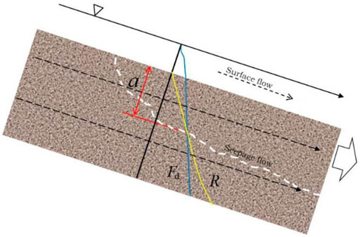
Currently, most calculations of the volume of solid material in small watersheds are based on statistics and estimations and can result in statistical errors ranging from 70% to 150%. For the design of debris-flow check dams, an unreasonable volume of loose solid material can lead to high costs or low preventability. Therefore, based on Yang’s (2014) research, we propose herein the concept of “movable solid materials”, which we define with the help of the critical depth a (see Figure 1), when the driving force exceed the resistance beneath the slope surface.
Thus, the movable solid materials are the solid materials within the critical depth when
Geological model of saturated seepage flow
The deposition mode and the amount of loose solid material in debris flow watershed affect the thickness of the loose solid material, the mechanical characteristics of the material, the slope angle, and various hydrodynamic characteristics. Generally, the motion of movable solid material is controlled by the relationships between slope angle, hydrodynamic conditions, gravity, and resistance. Given the definition, when the superposition of the hydrodynamic component and the gravity component exceeds the resistance, the solid material would lose failure and even initiate a debris flow.
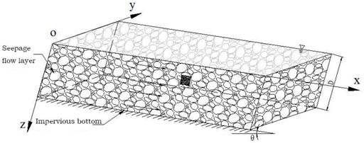
Water is the essential ingredient in debris flows and mainly comes from rainfall, surface water flow, and groundwater flow. The water movement occurs in saturated seepage flow, unsaturated flow, and surface flow. Figure 2 shows the model of saturated seepage flow of loose solid materials. We assume that the particles are heterogeneous and anisotropic. The porosity of the detrital grain layer is n, the thickness is D, the slope angle is θ, and the thickness of the surface water layer is H (H = 0 means an absence of surface water). Finally, the bottom plate is impermeable, and the saturated seepage flow is distributed over the whole layer.
Mechanics analysis
When the slope angle is less than the natural angle of repose, the loose solid materials remain static. However, a certain hydrodynamic contribution of seepage flow and surface flow will disturb the equilibrium, allowing the loose solid material to move in a debris flow. The seepage force and the drag force generated by surface flow are the main hydrodynamic forces and are related by the following equations.
The seepage force
where
For saturated seepage flow, we select a differential volume element
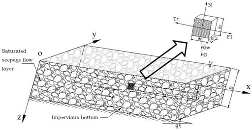
FIGURE 3. The mechanical analysis diagram of the solid materials unit under saturated seepage flow conditions.
The differential force dG of gravity exerted on the soil and water is
where
Therefore, the differential force exerted on the saturated layer in the x direction is
The differential force in the z direction is
The differential force
where
The differential force
The differential force
The differential seepage force
Considering the low flow velocity in the saturated layer, we set the flow velocity head difference to a minimum (∆u2 = 0). The volume element is taken to be parallel to the slope debris layer, and the water pressure on the upstream side is the same as that on the downstream side, so we can neglect the water pressure head. Therefore, Eq. 9 can be rewritten as follows.
During the seepage process, the particle framework prevents water flow in the pores between the particles. We assume dense debris so that the shear resistance
where
The dynamic force along the slope direction includes the seepage force and the force of gravity, which can be expressed as following
The force in the z direction is mainly composed of the gravity component
The pore-water pressure
Combined with the Mohr–Coulomb criterion, the differential resistance
Therefore, Eqs 12, 15 give the dynamic force and resistance exerted on the volume element, respectively, at the depth z and for saturated seepage flow. Eq. 12 consists of the seepage force
Eqs 12, 15 lead to an expression for the dynamic and resistance stress distribution vertical with respect to the slope direction for the volume element undergoing saturated seepage flow. Generally, the dynamic force and the resistance vary with slope angle, soil strength, and porosity of the layer. The depth z is the variable; the thickness of the volume element is dz, which we assume is the characteristic particle size
Results
Stress distribution
The porosity and density are constant when the slope layer contains homogeneous and isotropic particles, so the dynamic force and the resistance vary linearly with depth (i.e., with z). When the slope material consists of heterogeneous particles, the density and the porosity vary with depth, so the dynamic force and the resistance are nonlinear in depth. We assume a slope angle
Using the parameters given in Table 1 produces the distribution of dynamic force and resistance along the z direction shown in Figure 4.
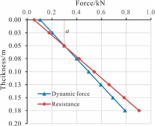
FIGURE 4. The stress distribution of movable solid materials under saturated seepage flow conditions.
From Figure 4, it shows that the dynamic force and resistance of movable solid material under saturated seepage flow are linear in depth. The results show that the critical thickness
Experiment verification and analysis
We now verify the formulas derived above against experiments carried out in a laboratory using the apparatus shown in Figure 5. This apparatus includes a water tank, flume, circular water pond, and frame. The flume slope can be adjust in different angles, and the flow route of the experiment can be captured from side view of the flume glass; the water pump can provide a constant flow of water from water pond.
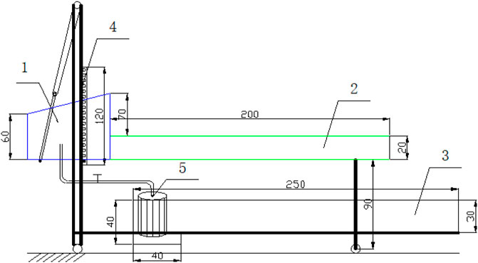
FIGURE 5. Schematic of the experimental setup (units in cm) one water tank, two experiment flume, three circular water pond, four frame, five water pump.
Two varieties of sand were used as the experimental materials for the geologic experiments. The parameters of these sands are listed in Table 2. The grain size distributions (1–2 and 2–5 mm) are isotropic. The water content of the sand is less than 3% in each experiment. The pore water pressure is recorded by sensors, the seepage flow discharge is fixed at 440 ml/s and the experimental slope angle is set as given in Table 3.
During the experiments, the sand starts to move as it undergoes seepage-flow infiltration. Each experiment can be stopped in two ways: when a section of sand collapses, or when the sand is stable for more than 5 min. All experiments were recorded by using a video camera.
The flow regime of experiments with different slope angles was recorded in side-view by the video camera, which shows that the sand layer evolves from stable to collapse upon saturation of the seepage flow infiltration (see Figure 6).
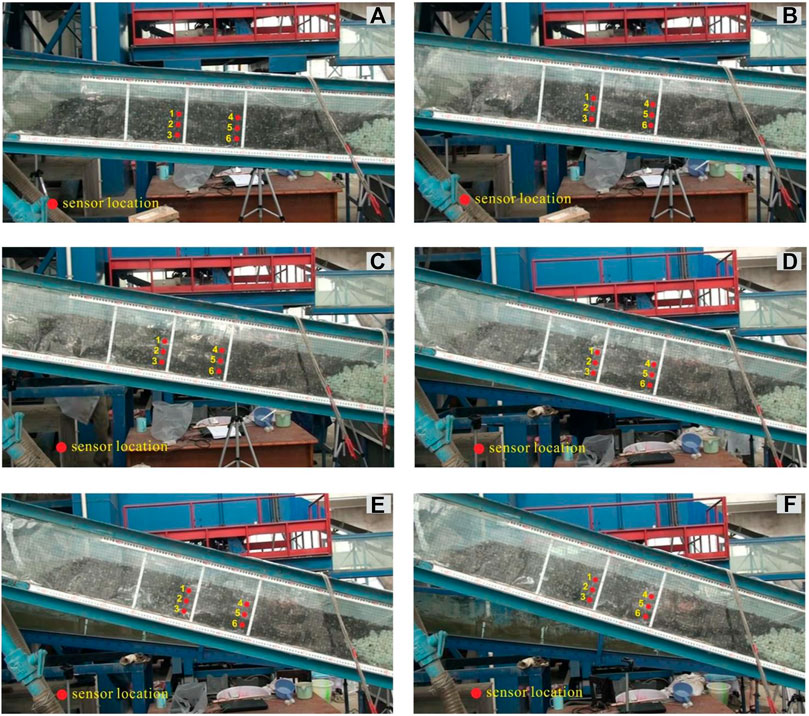
FIGURE 6. The flow regime under different slope angles (A) 6°, (B) 9°, (C) 12°, (D) 15°, (E) 18°, and (F) 20°; the red dots indicate the sensor locations in the center longitudinal section.
Figure 6 shows that, as the saturated seepage flow infiltrates into the sand layer, fine particles less than 2 mm in size move out through the outlet and large particles move after several seconds. Next, the whole layer collapses and the debris flow forms. This is especially apparent at the larger slope angles, such as 12°, 15°, 18°, and 20°. The pore-water sensors record the pore-water pressure. The red, blue, and green curves in Figure 7 show the results of sensors four to six, respectively.
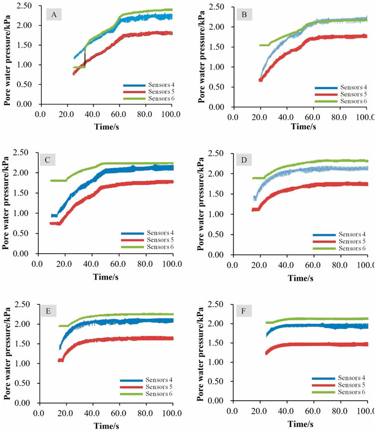
FIGURE 7. Pore-water pressure changes through the experimental process for various slope angles (A) 6°, (B) 9°, (C) 12°, (D) 15°, (E) 18°, and (F) 20°.
In the experiments, the water level in the sand layer rises rapidly and the sensors record significant variations in pore-water pressure with increasing water level, together with sand particle movements on the surface. When the slope angle is less than 12°, the pore-water pressure gradually stabilizes after the water level rises (see Figures 7A–C). The video data show that moving sand particles appear at 50 s and the thickness is less than 0.30 cm. When the slope angle exceeds 12°, sand particles move on the surface as the water level rises but stabilize quickly and then decrease slightly (see Figures 7D–F). In the video, the particle movement began after 30 s, and the thickness increases to over 2.90 cm.
Verification of dynamic expression
The experiment of water flow discharge was set to 440 ml/s and run with six different slope angles: 6°, 9°, 12°, 15°, 18°, and 20°. Since the sand particle size was 2–5 mm, each experimental layer was 0.80 m long by 0.20 m wide, and we assumed that the whole layer was isotropic. In addition, each seepage flow discharge was constant because the experimental conditions were the same. A geotechnical test gave a porosity n = 0.32, which was constant. In addition, the position of sand moving in this layer under different slopes was determined by visual interpretation of the experimental images. We then entered the data from the images into Eq. 16 and calculated the driving force under different conditions and compared the calculated results with the pore-water pressure recorded in each experiment. The parameters used in the formulas are given in Table 1, and the experimental and calculated results appear in Table 4. The parameters recorded in the table are the moving thickness for various slopes, the force of gravity exerted on the sand within the moving thickness, the pore-water pressure corresponding to sand motion during the test, and the dynamic theoretical pore-water pressure.

TABLE 4. Comparison of experiment value and calculation value under saturated seepage in 60 cm section.
According to the flume experiment record and the calculation by Eq. 16, it can attain the comparison between those two values, seen Figure 8.
From Figure 8, it shows that, with increasing flume slope angle, the seepage force in the sand particles varies. When the slope angle is less (greater) than 15°, the calculated value is smaller (greater) than the experimental value. For saturated seepage, the error analysis gives an error between the experimental and the calculated results from 1.3% to 24.2% percent, which shows that the theoretical results are consistent with the experimental results.
Discussion
Loose solid materials initiated by rainfall and surface flow have been widely researched (Takahashi 2007) and classified as either landslide-transforming type or water-erosion type. Based on hydraulic theory and assuming saturated seepage conditions, we derive dynamic force and resistance formulas that consider the force of gravity and pore-water pressure. Pore-water pressure depends on position and is difficult to measure because the position easily changes when the loose material layer fails. Thus, the model proposed in this work needs to be improved in future research.
Contrast between movable solid material and traditional solid material
The volume of loose solid materials is one of the most important parameters in the design of debris flow prevention (Ministry of Land and Resources of the People’s Republic of China, 2006). Many researchers have focused on the solid material content of a debris flow and numerous studies have used the terms of loose solid material, dynamical reserve, and effective solid materials, but the research methods were based on quantitative descriptions, field surveys, and calculations based on experiments. The contrast between movable solid materials and the traditional concept is made evident in Table 5.

TABLE 5. The contrast between movable solid materials and traditional loosen solid materials concept.
Solid material is a defined qualitative concept in traditional debris flow studies, but a definition of what kind of loose content will form a debris flow under specific hydrologic conditions has still not appeared in published research. In practical applications, most volume calculations of loose solid material are based on field survey estimates. The debris-flow dynamical reserve of the loose solid material volume can be calculated by measuring the length, width, and estimated potential thickness. However, a problem with this approach is that the estimated thickness originated from investigating outside and there is no practical meaning. The thickness should be controlled by the mechanical properties of the solid materials. The effective solid materials concept is defined as the solid material that joins the debris flow because of water, but this concept does not apply in the current example.
The potential movement of loose solid materials down a sloped surface and the quantity of solid material that moves due to rainfall is a mechanical problem that should be treated by propulsion and resistance. As with the analysis above, the dynamic propulsion includes seepage flow, surface flow, and gravity components. The debris-flow dynamic propulsion contributed by rainfall can be calculated based on rainfall, runoff, and convergence for a certain frequency of rainfall. Resistance is due to cohesion, friction, and shear resistance between particles in the soil layer. The concept of a moving solid material is based on mechanical equilibrium, which has a clear physical meaning, in contrast with the traditional definition.
Dynamic characteristics of soil-mechanical and water-mechanical debris flow
Based on the diversity of dynamic characteristics, debris flows can be divided into soil-mechanical and water-mechanical debris flows. With the former, the debris flow moves over the slope, the driving force consists of gravity and the soil shearing force, and the loose soil materials are mainly generated by rock falls and landslides. With the latter, the slope over which the debris flows route is less than 15°, and the driving force comes from hydrodynamics and gravity, so the loose solid material is mainly deposited on the gully sides and at the slope toe in the form of rock avalanches and slope bodies. Currently, significant research has focused on debris-flow initiation in the source area, which is caused by rainfall and surface water, whereas few studies have focused on the characteristics of the loose solid materials of a debris flow area under seepage flow and surface flow. In the latter category, Takahashi (2007) systematically studied the debris flow initiation mechanism in a saturated soil layer with seepage and thin surface water flow.
Field surveys and experiments indicate that loose solid materials are distributed widely in the debris flow watershed, but the area and volume are distributed randomly. Specially, slope materials is one of the important supplies of material for debris flows, field survey show that the slope failures are random and discontinuous in each landslide (Guo et al., 2021). Heterogeneous characteristics are reflected in the wide range of grain sizes and particle densities that depend on the source rock. Anisotropy in porosity, strength, seepage, and rheology means that these parameters also depend on direction. In addition, soil-water content and the changeable topographic surface also significantly affect the water confluence, seepage field, and runoff field.
There are two common particle types in loose solid materials: one is coarse particles that constitute the framework of the soil, and the other is fine particles that fill in the pore space of the framework. The stability of the slope is determined by the shear resistance of the coarse particles. Under seepage flow, the fine particles are carried away by the seepage force, which changes the viscosity of the seepage flow. With increasing loss of fine particles, the framework may be destroyed by the shear force. Thus, given abundant loose solid materials in the topography, the seepage force and surface flow mechanics control the layer’s destruction form, and the movable thickness and the spatial distribution are determined by the gross volume of the loose solid materials.
Conclusion
Loose solid materials transform into debris flows under the seepage flow effect is one of the most common natural disasters in mountainous areas. The high frequency of debris flow events in the rainy season pose significant risk to local people’s lives and properties and require rehabilitation and reconstruction scientifically.
Water and loose solid materials are essential components of a debris flow. Based on the principle of mechanical equilibrium, this work defines movable solid materials and expresses clearly the movable characteristics of a debris flow firstly. Movable solid materials become relevant when the dynamic force is greater than the resistance, which define with the critical depth.
Taking saturated seepage flow as an example, a geologic model is set up and a mechanical analysis is carried out. A dynamic force formula and a resistance formula are derived based on specific conditions. When the geologic model is homogenous and the seepage flow saturates the whole debris layer, the dynamic force and resistance increase linearly with depth for the given parameters.
Mechanical analysis and laboratory experiments show that fine sand particles are carried out of the layers by seepage water flow and that the pore-water pressure is a vital driving force, which confirms the results of previous research, especially when the slope angle exceeds 12°. Comparing the experimental results with the calculated results under saturated seepage flow reveals a discrepancy of 1.3%–24.2% for the assumed conditions, showing that the calculated results are suitably accurate.
By considering the concepts, calculations, and mechanics of traditional solid materials and movable solid materials, we conclude that the motion of loose solid materials due to hydrodynamic forces is a mechanical problem rather than the traditional problem of qualitative description and estimation. Thus, further study of movable solid materials in complex dynamic condition is required.
Data availability statement
The original contributions presented in the study are included in the article/supplementary material, further inquiries can be directed to the corresponding author.
Author contributions
SY carried out experiment design, data analysis and manuscript writing. MG taken the experiment, participated in the discussion and decision-making process. JJ taken out of the experiment and discussion in advance. TS writing reviewing. KC carried out the manuscript editing and supervision. All the authors participated and contributed to the final manuscript.
Funding
This research work was supported by the Talent Introduction Program of Xihua University (Grand No. Z211016), the Opening Foundation of Key Laboratory of Geohazard Prevention of Hilly Mountains, Ministry of Natural Resources (Grant No. FJKLGH 2022K005) and the National Natural Science Foundation of China (Grant No. 41502330).
Conflict of interest
The authors declare that the research was conducted in the absence of any commercial or financial relationships that could be construed as a potential conflict of interest.
Publisher’s note
All claims expressed in this article are solely those of the authors and do not necessarily represent those of their affiliated organizations, or those of the publisher, the editors and the reviewers. Any product that may be evaluated in this article, or claim that may be made by its manufacturer, is not guaranteed or endorsed by the publisher.
Acknowledgments
The authors appreciate the editors and reviewers for their critical and valuable comments and suggestions that greatly helped us to improve the present manuscript. We would also like to thank Charlesworth Author Services [https://www.cwauthors.com.cn] for English language editing work.
References
Carey, J., Cosgrove, B., Norton, K., Massey, C. I., Petley, D. N., and Lyndsell, B. (2021). Debris flow-slide initiation mechanisms in fill slopes, Wellington, New Zealand. Landslides 18, 2061–2072. doi:10.1007/s10346-021-01624-6
Carey, J., Massey, C., Lyndsell, B., and Petley, D. (2019). Displacement mechanisms of slow-moving landslides in response to changes in pore water pressure and dynamic stress. Earth Surf. Dynam. 7 (3), 707–722. doi:10.5194/esurf-7-707-2019
Chen, H., Dadson, S., and Chi, Y.-Q. (2006). Recent rainfall-induced landslides and debris flow in northern Taiwan. Geomorphology 77, 112–125. doi:10.1016/j.geomorph.2006.01.002
Chen, N., Gao, Y., Yang, C., and Hu, G. s. (2018). Effect of clay content to the strength of gravel soil in the source region of debris flow. J. Mt. Sci. 15, 2320–2334. doi:10.1007/s11629-018-4911-8
Chen, N., Zhou, W., Yang, C., Hu, G., Gao, Y., Han, D., et al. (2010). The processes and mechanism of failure and debris flow initiation for gravel soil with different clay content. Geomorphology 121 (3-4), 222–230. doi:10.1016/j.geomorph.2010.04.017
Cui, P., Hu, K., Zhuang, J., Yang, Y., and Zhang, J. (2011). Prediction of debris flow danger area by combining hydrological and inundation simulation methods. J. Mt. Sci. 8 (1), 1–9. doi:10.1007/s11629-011-2040-8
Dahal, R., Hasegawa, S., Nonomura, A., Yamanaka, M., Masuda, T., Nishino, K., et al. (2009). Failure characteristics of rain fall-induced shallow landslides in granitic terrains of Shikoku Island of Japan. Environ. Geol. 56 (7), 1295–1310. doi:10.1007/s00254-008-1228-x
Degetto, M., Gregoretti, C., and Bernard, M.(2015). Comparative analysis of the differences between using LiDAR and contour-based DEMs for hydrological modeling of runoff generating debris flows in the Dolomites. Front. Earth Sci. 49 3, 21. doi:10.3389/feart.2015.00021
Emmanuel, J., and Simon, M. (2006). The mobilization of debris flows from shallow landslides. Geomorphology 74, 207–218. doi:10.1016/j.geomorph.2005.08.013
Guo, C., and Cui, Y. (2020). Pore structure characteristics of debris flow source material in the Wenchuan earthquake area. Eng. Geol. 267 (1), 105499. doi:10.1016/j.enggeo.2020.105499
Guo, X., Li, Y., Cui, P., Yan, Y., Wang, B., Zhang, J., et al. (2021). Spatiotemporal characteristics of discontinuous soil failures on debris flow source slopes. Eng. Geol. 295, 106438. doi:10.1016/j.enggeo.2021.106438
Hossein, G., and Soheil, G. (2008). Stability of sandy slopes under seepage conditions. Landslides 5, 397–406. doi:10.1007/s10346-008-0132-5
Hu, W., Dong, X., Wang, G., van Asch, T., and Hicher, P. (2016). Initiation processes for run-off generated debris flows in the Wenchuan earthquake area of China. Geomorphology 253, 468–477. doi:10.1016/j.geomorph.2015.10.024
Hu, W., Xu, Q., Wang, G., van Asch, T., and Hicher, P. (2015). Sensitivity of the initiation of debris flow to initial soil moisture. Landslides 12, 1139–1145. doi:10.1007/s10346-014-0529-2
Iverson, R., and Schaeffer, D. (2004). Regulation of landslide motion by dilatancy and pore-pressure feedback. AGU Fall Meeting, 273–280.
Li, Q., Huang, D., Pei, S., Qiao, J., and Wang, M. (2021). Using physical model experiments for hazards assessment of rainfall-induced debris landslides. J. Earth Sci. 32, 1113–1128. doi:10.1007/s12583-020-1398-3
Li, X., Huang, X., and Zhang, Y. H. (2021). Spatio-temporal analysis of groundwater chemistry, quality and potential human health risks in the Pinggu basin of North China Plain: Evidence from high-resolution monitoring dataset of 2015–2017. Sci. Total Environ. 800, 1495568. doi:10.1016/j.scitotenv.2021.149568
Liu, J., You, Y., Chen, X., and Fan, J. (2010). Identification of potential sites of debris flows in the upper Min River drainage, following environmental changes caused by the Wenchuan earthquake. J. Mt. Sci. 3, 255–263. doi:10.1007/s11629-010-2017-z
Mao, C., and Duan, X. (2009). On seepage forces and application. Rock Soil Mech. 30 (6), 1569–1574. (in Chinese). 10.00-7598(2009)06-1569-07.
McCoy, S., Kean, J., Coe, J., Tucker, G., Staley, D., Wasklewicz, T., et al. (2012). Sediment entrainment by debris flows: In situ measurements from the headwaters of a steep catchment. J. Geophys. Res. 117 (F3). doi:10.1029/2011jf002278
Ministry of Land and Resources of the People’s Republic of China (2006). Specification of geological investigation for debris flow stabilization. DZ\T 0220. Beijing: Ministry of Land and Resources of the People’s Republic of China. (in Chinese).
Qiao, J., Huang, D., and Yang, Z. (2012). Statistical method on dynamic reserve of debris flow's source materials in meizoseismal area of wenchuan earthquake region. Chin. J. Geol. Hazard Control 23 (02), 1–6. (in Chinese). doi:10.3969/j.issn.1003-8035.2012.02.001
Richard, M. (2005). Regulation of landslide motion by dilatancy and pore pressure feedback. J. Geophys. Res. 110 (F2), F02015. doi:10.1029/2004JF000268
Sassa, K., Fukuoka, H., Wang, G., and Ishikawa, N. (2004). Undrained dynamic-loading ring-shear apparatus and its application to landslide dynamics. Landslides 1 (1), 7–19. doi:10.1007/s10346-003-0004-y
Takahashi, T. (2007). Debris flow: Mechanics, prediction and countermeasures. London, UK: Taylor and Francis Group, 33–101.
Tang, C., Li, W., and Ding, J. (2011). Field investigation and research on giant debris flow on august 14, 2010 in yinxiu town, epicenter of wenchuan earthquake. Earth Science-Journal China Univ. Geosciences 36 (1), 172–180. (in Chinese). doi:10.3799/dqkx.2011.018
Wang, G., and Sassa, K. (2003). Pore-pressure generation and movement of rainfall-induced landslides: Effects of grain size and fine-particle content. Eng. Geol. 69, 109–125. doi:10.1016/S0013-7952(02)00268-5
Wang, J., Cui, P., Wang, H., Zhang, G., Zou, Q., Chen, X., et al. (2022). Novel approach to estimating glacial moraine reserves in the Parlung Tsangpo basin. Front. Earth Sci. 10, 853089. doi:10.3389/feart.2022.853089
Xu, Q. (2010). The 13 august 2010 catastrophic debris flows in sichuan province: Characteristics, genetic mechanism and suggestions. J. Eng. Geol. 18 (5), 576–608. (in Chinese). doi:10.04-9665/2010/18(5)-0596-13
Yang, S. (2014). Study on the movable critical model of solid materials under hydro-dynamical condition in debris flow area. Beijing: University of Chinese Academy of Sciences, 2–4. (in Chinese).
Zhang, Y. H., Dai, Y. S., Wang, Ying, Huang, X., Xiao, Y., Pei, Q. M., et al. (2021a). Hydrochemistry, quality and potential health risk appraisal of nitrate enriched groundwater in the Nanchong area, southwestern China. Sci. Total Environ. 2021, 784147186. doi:10.1016/j.scitotenv.2021.147186
Zhang, Y. H., He, Z. H., Tian, H. H., Huang, X., Zhang, Z. X., Liu, Y., et al. (2021b). Hydrochemistry appraisal, quality assessment and health risk evaluation of shallow groundwater in the Mianyang area of Sichuan Basin, southwestern China. Environ. Earth Sci. 80 (17), 576. doi:10.1007/s12665-021-09894-y
Keywords: debris flow, seepage flow effect, solid materials, movable, experiment
Citation: Yang S, Gao M, Jiao J, She T and Chen K (2022) The effect of seepage flow on movable solid materials research in debris flow experiments. Front. Earth Sci. 10:896897. doi: 10.3389/feart.2022.896897
Received: 15 March 2022; Accepted: 27 June 2022;
Published: 14 July 2022.
Edited by:
Yunhui Zhang, Southwest Jiaotong University, ChinaCopyright © 2022 Yang, Gao, Jiao, She and Chen. This is an open-access article distributed under the terms of the Creative Commons Attribution License (CC BY). The use, distribution or reproduction in other forums is permitted, provided the original author(s) and the copyright owner(s) are credited and that the original publication in this journal is cited, in accordance with accepted academic practice. No use, distribution or reproduction is permitted which does not comply with these terms.
*Correspondence: Shun Yang, eWFuZ3NodW4wOUBmb3htYWlsLmNvbQ==
 Shun Yang
 Meiben Gao
 Jiaxua Jiao
 Tao She
 Kun Chen1,2