 Ning Wang
 Yalong Jiang
 Daxin Geng
 Zhanjun Huang
 Haibin Ding
- 1Institute of Geotechnical Engineering, School of Civil Engineering and Architecture, East China Jiaotong University, Nanchang, China
- 2Jiangxi Key Laboratory of Infrastructure Safety and Control in Geotechnical Engineering, East China Jiaotong University, Nanchang, China
- 3Nanchang Rail Transit Group Limited Corporation, Nanchang, China
In this study, the combined influence of shield tunneling and the old pile cutting process on underpinning piles is investigated through finite element method (FEM) modeling based on a shield tunnel project in Nanchang Metro Line 2, China. Numerical models have been developed to analyze the influence of intersection angles and the vertical distance between the underpinning foundation and tunnels on the mechanical responses of underpinning piles during tunnel excavation. Simulation results show that the bending moment of the underpinning piles decreases with increasing vertical distance between the pile and tunnel, and is inversely proportional to the intersection angle between the underpinning beam and tunnel. In addition, the maximum pile bending moment occurs in the buried depth of the tunnel axis, indicating a high risk of damage in this part. According to the simulation results, more attention should be given to the underpinning piles in case a small vertical distance and intersection angle are encountered.
Introduction
With the rapid development of the urban metro system, an increasing number of tunnels are being constructed in China (Ding and Xu 2017; Wang et al., 2018). However, tunnel excavation induces the deformation of the surrounding soil (Chen et al., 2016) and adjacent structures, such as buildings, existing tunnels, and buried pipelines (Liao et al., 2009). Hence, minimizing the interference of the tunnel construction process on adjacent structures has attracted the attention of engineers and scholars in the field of geotechnical engineering (Verruijt and Booker 1996; Park 2005; Lin et al., 2013).
In recent years, significant efforts have been made to investigate the influence of tunnel construction on adjacent structures and ground deformation (Dimmock and Mair 2008; Mirhabibi and Soroush 2012; Liu et al., 2014; Hong et al., 2015). Since shield tunneling has a significant influence on the surrounding pile foundations (Meguid and Mattar 2009; Yang et al., 2009; Huang and Mu 2012; Lee 2012), considerable amount of attention has been given to this issue by researchers. The research approaches include model tests (Loganathan et al., 2000; Jacobsz et al., 2004; Soomro et al., 2015), centrifuge experiments (M. and J. 2011; Marshall 2012; Ng and Lu 2014; Ng et al., 2014), and numerical simulations combined with field monitoring (Xu and Poulos 2001; Cheng et al., 2007; Zhang et al., 2013; Soomro et al., 2017). Chen et al. (1999) found that tunnel excavation results in significant bending moments in piles, and the pile behavior was affected by various factors, including the tunnel geometry, soil properties, pile diameter, and the ratio of pile length to tunnel coverage depth. Huang et al. (2009) analyzed the variation in the bending moments of piles during tunnel excavation by comparing the results of various centrifuge and numerical models, which precisely revealed the response of passive piles subjected to tunneling. Loganathan et al. (2000) studied the influence of tunnel construction on adjacent pile foundations through three centrifugal model tests, and the results indicated that the bending moment and lateral deformation of the pile were significantly influenced by the construction of the tunnel when the centerline of the tunnel was near the pile tip. Regarding numerical modeling, Pang et al. (2005)analyzed the influence of a double-track tunnel construction on the existing pile foundation based on a real case of the MRT North-East Line in Singapore using a three-dimensional FEM model. The influences of face pressure, shield tunnel advancement, over-cutting, tail void closure, and installation of lining were numerically investigated and were verified by comparison with field monitoring data. A three-dimensional elastoplastic coupling consolidation model was developed by Lee and Ng (2005) to analyze the bending moment of piles during tunnel excavation, indicating that the tunnel excavation did not significantly affect the existing bending moment and the axial structural load distribution within the pile. Utilizing a three-dimensional finite element model, Lee (2013) investigated the influence of open-air tunnel construction in hard clay on adjacent piles and revealed the basic load transfer mechanism as well as the mechanical responses of the piles. Research results showed that the bearing capacity of piles experiencing adjacent tunneling is more significantly affected by pile settlement than that by axial pile force changes, in particular for piles inside groups. Soomro et al. (2015) numerically studied the tunneling effects on an existing 2×2 pile group, and the results indicated that the bending moment induced by the tunnel excavation of each front pile was the most significant while tunneling near the mid-depth of the pile group (i.e., cover-to-diameter-of-tunnel ratios of 1.5).
However, once the existing pile foundations of the surrounding buildings invaded the shield tunnel line, old pile cutting and underpinning pile construction were necessary to protect the existing structures. In the foundation underpinning, the plies that intruded into the designed tunnel area were cut off after underpinning piles were constructed, creating a new foundation of the upper structure (Li et al., 2021). This engineering process is very complex, involves complicated interactions of the tunnel, soil and pile foundation, and has attracted a considerable amount of attention from researchers and engineers. Based on the expansion project of St. Joseph Mercy Hospital in Georgetown, Guyana, Stulgis et al. (2004) pointed out that the pile foundation should be replaced before the destructive settlement of the building, and that grouting micropiles should be installed in the replacement area to effectively ensure the safety of the structures. Taking the Xi’an Metro shield tunnel project as an example, Ma and Wang (2012) obtained the bearing capacity of a single pile and the joist deformation through theoretical calculations according to the structural design, which indicated that the pile foundation underpinning method is valid. Yao et al. (2012) analyzed the pile foundation underpinning scheme for Beijing Metro Line 8 using the finite difference software of FLAC3D, indicating the effectiveness of pile foundation underpinning in reducing the deformation of structures and isolating piles. Combining theoretical calculations and field model tests, Yan et al. (2018) obtained the shear formula of a pile foundation underpinning structure to calculate the shear bearing capacity of the structure. Based on the practical shield cutting pile engineering case, in which bridge piles with a large-diameter of 14 m were cut by a shield machine, Chen et al. (2016) analyzed the effect and mechanism of cutting piles, the characteristics of cutting parameters and the damage law of cutting tools through field tests. Subsequently, a configuration plan for the advanced shell cutter and the cutting concept of sub-cut ribs were proposed (Yuan et al., 2016). It was recommended that the pushing speed did not exceed 2 mm/min, and that the rotation speed of the cutter head was in a reasonable range. Fu (2014) simulated small diameter (400 mm) shields to cut plain concrete, glass fiber concrete, and reinforced concrete to study the feasibility of the direct shield cutting pile foundation construction technology, and the transformation of the shield cutter head as well as the control data of tunneling construction parameters were analyzed. Currently, most of the research on this topic has focused on the design and optimization of the underpinning scheme, whereas the corresponding force transfer mechanism and the influence on shield tunnel construction as well as the deformation mechanism of new pile foundation was neglected (Li et al., 2021). Moreover, the previous studies did not consider the influence of the intersection angles and vertical distances between the new underpinning piles and the tunnel on the underpinning plies, which is one of the key factors for selecting the underpinning scheme for a certain case.
To overcome the aforementioned limitations, numerical analysis is conducted in this study using the 3D finite element software ABAQUS to investigate the combined influence of shield tunneling and pile cutting on underpinning piles based on the shield tunnel project of Nanchang Metro Line 2 in China. Numerical models are established using ABAQUS to study the influence of the shield excavation and pile cutting process on the new underpinning piles, and the possible engineering problems during tunnel construction are analyzed. By comparing the results of the pile bending moments, shear forces, and displacements, the influence of shield tunnel and pile cutting on the change of pile spacing and intersection angles are obtained, based on which reasonable suggestions are given for optimization of the underpinning pile scheme.
Study Area
The comprehensive construction of Metro Line 2 in Nanchang City began in July 2013 and was completed in August 2017 with the total length of 42.2 km. Between the Honggu Avenue (Middle) Station and the Yangming Park Station of Metro Line 2 in Nanchang, seven bridge piles of the south approach of the Bayi Bridge intruded into the tunnel excavation area as shown in Figure 1A. To ensure the safety and stability of the Bayi Bridge during tunneling, underpinning piles were built, and five bridge piles, namely, L1, L2, L3, R1, and R2, were subsequently cut by a shield machine, as shown in Figure 1B. The soil profile in the location of the underpinning piles is shown in Figure 1C.
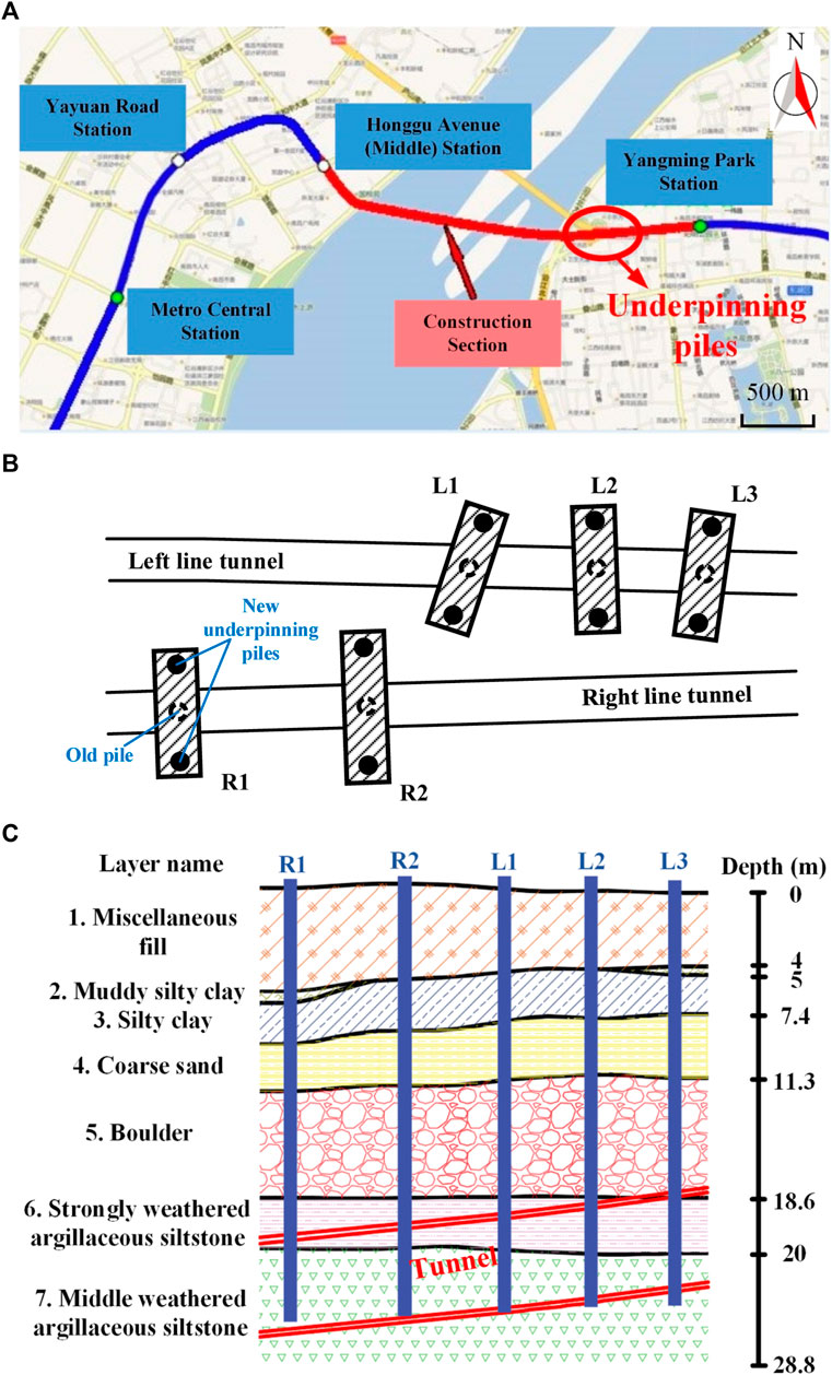
FIGURE 1. Basic information of the study area: (A) location of the underpinning piles; (B) layout of the underpinning piles; (C) soil profile in the location of underpinning piles.
Numerical Modeling
Model Establishment
To investigate the influence of shield tunneling on the existing bridge, a 3D FEM model is established using ABAQUS software. As shown in Figure 2A, the size of the model stratum is 50.0 m (length)×40.0 m (width)×50.0 m (height), and the underpinning beam is 14.4 m (length)×5.5 m (width)×3 m(height). As shown in Figure 2B, the length and diameter of the existing pile are 24.8 and 1.2 m, respectively, which is truncated before tunnel excavation. The underpinning piles have a length of 27.0 m and a diameter of 1.2 m on both sides of the old pile. The diameter of the shield tunnel is 6.0 m with a segment thickness of 0.3 m. The calculation element for the 3D numerical model is C3D8R with a total element number of 88,864. The normal displacement of all boundaries of the soil model was constrained, and the bottom of the model was fixed.
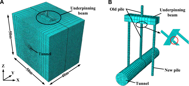
FIGURE 2. Model geometry and mesh: (A) finite element model; (B) underpinning structure and tunnel.
The Mohr–Coulomb model, which has been proven applicable in previous literature works, is adopted to model the mechanical behavior of the soil. The lining, underpinning beam, and pile are modeled as homogeneous and linear elastic materials. The parameters of the soil layers and concrete structures are presented in Table 1.
TABLE 1. Material properties.
Tunneling Process Simulation
Soil excavation and pile cutting in the shield tunneling process are simulated using the birth–death element method. As shown in Figure 3A, the tunneling process is divided into 21 steps, in which the pile truncating (shown in Figure 3B) was located at the area of rQZ. To simulate the shield tunneling process, a grouting pressure of 0.07 MPa, which is consistent with the synchronous grouting pressure adopted in the practical engineering case, is applied around the excavated soil surface, and the grouting pressure is removed instead of a 0.3 m thick lining immediately after each soil excavation step. Considering the thrust exerted by the shield on the tunnel face, a driving force of 150.0 kN is also applied to each excavation step in the simulation process (shown in Figure 3C). In addition, the shield machine may bear additional driving forces during pile cutting. Therefore, the driving force is increased to 200.0 kN in the rQZ step.
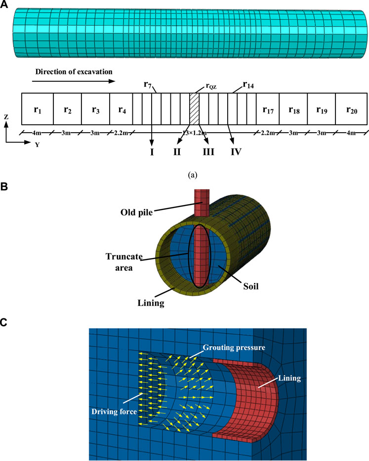
FIGURE 3. Numerical modeling of the tunneling process: (A) schematic diagram of the shield tunneling process; (B) schematic diagram of the existing pile truncating; (C) driving force and grouting pressure during tunneling.
Numerical Results and Discussion
Analysis Methods
In this section, the influence of the layout of the underpinning pile is investigated in four different tunneling stages: stage I—tunneling toward the existing pile, stage II—tunneling before the existing pile cutting, stage III—tunneling after the existing pile cutting, and stage IV—tunneling away from the existing pile (as shown in Figure 3A).
To study the influence of the shield cutting of the piles on the underpinning piles at different distances, the method of changing the length of the underpinning beam and the distance between the new underpinning piles is adopted while the intersection angle between the underpinning beam and the tunnel axis remains 90°. The distances between the new underpinning piles of model 1 (Figure 4A), model 2 (Figure 4B), and model 3 (Figure 4C) are 12.0, 14.0, and 16.0 m, respectively, and the distance between the new underpinning pile and the outer end of the underpinning beam is 0.6 m.
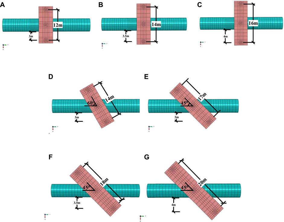
FIGURE 4. Numerical models with different spacing distance between underpinning piles and different intersection angles between underpinning beams and tunnel: (A) model 1; (B) model 2; (C) model 3; (D) model 4; (E) model 5; (F) model 6; (G) model 7.
To further study the influence of the shield cutting of the piles on the underpinning piles at different angles, the method of changing the length of the underpinning beam is adopted for analysis under the condition that the distance between the two underpinning piles and the tunnel remains unchanged, as shown in model 4 (Figure 4D) and model 5 (Figure 4E). When θ = 60° in Figure 4D, the distance between the piles is 14.0 m. When θ = 45° in Figure 4E, the distance between the piles is 17.0 m. However, the vertical distance between the new underpinning pile and the outer boundary of the tunnel is 3.0 m, and the distance between the new underpinning pile and the outer end of the underpinning beam is 0.6 m.
To explore whether or not the pile is more dangerous with a small intersection angle than a small distance, three different models are built for analysis (i.e., model 5, model 6, and model 7), as shown in Figures 4E–G. In the three models, the intersection angle remains 45°, while the distances between the two new underpinning piles are 17.0, 18.0, and 20.0 m, respectively. The parameters of the models are shown in Table 2, and all the dimensions in this calculation process are approximated.
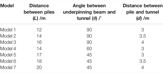
TABLE 2. Model parameters.
Influence of Pile Spacing on the Bending Moment of the Underpinning Piles Under Different Working Conditions
Figure 5 presents the influence of pile spacing on the bending moment of the underpinning pile under different working conditions. It is observed that there are two peaks of the bending moment, one of which is located at a depth of about 8 m of piles, and the other one is at the central axis of the tunnel. Near the tunnel excavation area, the bending moment of the new palletized pile for the four working conditions decreases with an increase in the distance between the new underpinning pile and the tunnel. In working condition II, the bending moment at the central axis of the tunnel increases rapidly due to the combined effect of shield and pile cutting. When L = 12.0, 14.0, and 16.0 m, the increase rates are 46, 70, and 73%, respectively, compared with condition I.
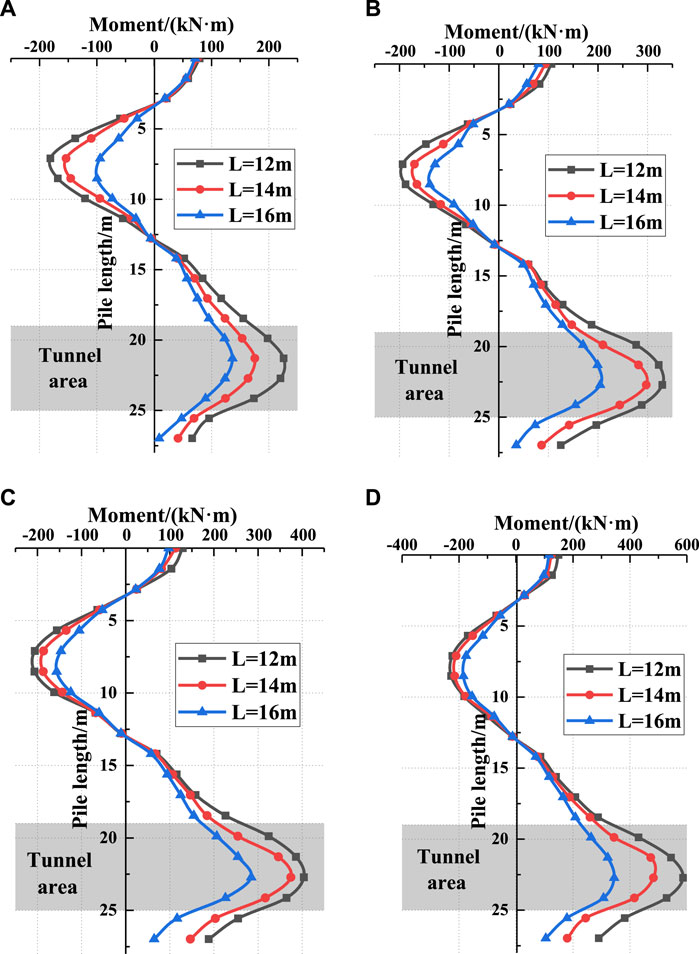
FIGURE 5. Bending moment distribution of piles under different working conditions: (A) working condition I; (B) working condition II; (C) working condition III; (D) working condition IV.
Under working condition I, the amount of the negative bending moment above the tunnel area is almost the same as the amount of the positive bending moment in the tunnel area. Under working conditions II, III, and IV, the amount of the negative bending moment above the tunnel area is stable below 200.0 kNm, whereas the amount of the positive bending moment in the tunnel area increases gradually with the development of the shield. This shows that the change and influence of the bending moment of the new underpinning pile on the central axis of the tunnel should be given more attention in shield tunneling.
Influence of the Working Condition on the Bending Moment of the Underpinning Piles Under Different Pile Spacings
Figure 6 shows the influence of the working condition on the bending moment of the underpinning pile under different pile spacings. It is observed that the bending moment of the underpinning pile increases with the shield tunneling, and this effect is more significant at the depth of the central axis of the tunnel. In case I, because the shield machine is far away from the pile, the bending moment of the pile is not much different for different distances, but the growth rate is different. In case IV, the maximum bending moments at L = 12.0, 16.0, and 20.0 m are 587.0 kN·m, 482.0 kN·m, and 345.0 kN·m, respectively.
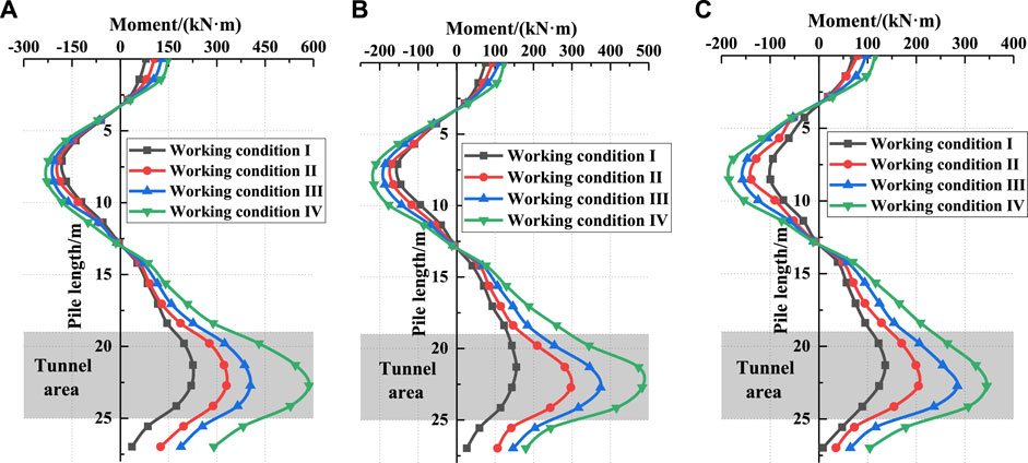
FIGURE 6. Bending moment distribution of piles at different distances: (A) L=12 m; (B) L=16 m; (C) L=20 m.
The influence increases with the decrease in the distance between the pile and the tunnel. The location where the negative bending moment is largest is near a burial depth of 7.0 m, and the location where the positive bending moment is largest is at the central axis of the tunnel. In the case of different distances, two reverse bending phenomena in the change in the bending moment of the whole pile are observed. The first reverse bending point located is at the range from 3.0 to 5.0 m of the pile, while the second one appears in the range from 13.0 to 14.0 m of the pile. The aforementioned analysis shows that the pile body bending moment at the central axis of the tunnel is the largest, regardless of the pile spacing and working conditions.
Influence of the Intersection Angle on the Bending Moment of the Underpinning Piles in Different Excavation Steps
Shield tunneling has different impacts on the piles for different intersection angles under different working conditions. Hence, the bending moment of the pile body corresponding to the central axis of the tunnel is selected to analyze the influence of the shield on the pile foundation at different angles.
Figure 7A shows the influence of the intersection angle on the bending moment of the left underpinning pile in different excavation steps. It is observed that the bending moment of the underpinning pile with the intersection angle of 45° is significantly greater than that of the piles with intersection angles of 60° and 90° during the whole tunneling process. At the beginning of shield tunneling, the bending moment of the underpinning pile increases slowly. The bending moment increases rapidly adjacent to the pile cutting step. Finally, the bending moment tends to be stable. These stable bending moment values of the underpinning pile with intersection angles of θ = 60° and θ = 45° are 30 and 49%, respectively, higher than those with an intersection angle of θ = 90°. The reason is that the shield machine approaches the pile at 45° sooner, so that the pile is first affected. Hence, the smaller the intersection angle is, the more the pile is affected. The bending moment is relatively large, and it is also the first to stabilize. However, from the perspective of the growth rate of bending moments for the three different intersection angles, the smaller the angle is, the faster the growth rate of the bending moment. This shows that when the distance between the pile and the tunnel remains constant, smaller intersection angle usually induces higher engineering risks.
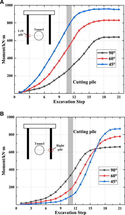
FIGURE 7. Bending moment of the new underpinning piles at different angles: (A) left pile; (B) right pile.
Figure 7B shows the changes in the bending moments of the right piles at three different intersection angles as excavation progresses. In the first half of the excavation, the bending moment is relatively large and stabilized earlier because the shield machine first passes the 90° pile. As the excavation progresses, the bending moment of the pile with a small intersection angle continues to increase until the shield machine moves away, and the bending moment eventually stabilizes. Therefore, in the subsequent excavation, the bending moment with a small intersection angle is larger. However, from the perspective of the growth rate, the smaller the intersection angle between the new underpinning piles and the tunnel is, the faster the growth rate of the bending moment is, indicating that a pile with a small intersection angle is more dangerous during the construction process, which is the same as the trend of the left pile.
Influence of Pile Spacing on the Bending Moment of the Underpinning Piles in Different Excavation Steps
To verify that piles with small intersection angles and small distances are more dangerous, a group of models (i.e., models 5, 6, and 7 shown in Figure 4) are adopted, in which the pile spacings are 17.0, 18.0, and 20.0 m, respectively, while the intersection angle θ remains 45°.
The bending moment of the left pile increases with the shield tunneling process, as shown in Figure 8A. The smaller the distance is, the greater the growth rate of the bending moment is, and the larger the stable bending moment value tends to be. The final bending moment values of d = 3.5 m and d = 3.0 m are increased by 7 and 36%, respectively, compared with d = 4.0 m. This also reflects that the pile is relatively safe when d ≥ 3.5 m.
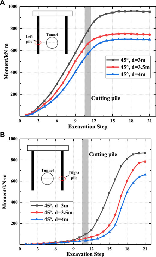
FIGURE 8. Bending moment of the piles at different distances when θ=45°: (A) left pile; (B) right pile.
As shown in Figure 8B, when the shield machine is far from the right pile, the bending moment of the pile is small. However, while the shield machine approaches the right pile, the bending moment increases rapidly. When d = 4.0, 3.5, and 3.0 m, the final bending moment values are 867.0 kN m, 785.0 kN m, and 661.0 kN m, respectively. Compared with d = 3.0 m, the final bending moment values of d = 3.5 m and d = 4.0 m increase by 19 and 10%, respectively. This also proves that the piles with small distances and small intersection angles have greater bending moment changes under the influence of tunnel excavation and pile cutting.
Influence of the Shear Force of the Underpinning Piles in Different Excavation Steps
To facilitate the study of the influence of shield tunnels and the removal of old piles on the shear force (X-direction) and lateral displacement (X-direction) of the underpinning piles, the data of some construction steps and a total of 11 steps are analyzed, as shown in Figure 9.
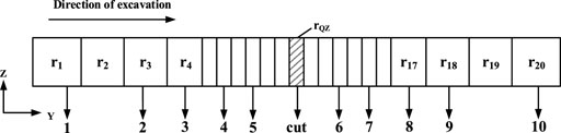
FIGURE 9. Working conditions.
As shown in Figure 10, the largest shear force appears at the top and bottom of the tunnel area for the last step of excavation and is 0 at the tunnel axis. The shear force of the pile body is small before pile cutting but increases rapidly afterward and finally tends to be stable, which shows that the influence of pile cutting on the pile shear force is very large. The maximum shear forces at L = 12.0, 16.0, and 20.0 m are 367.0, 291.0, and 181.0 kN, respectively.
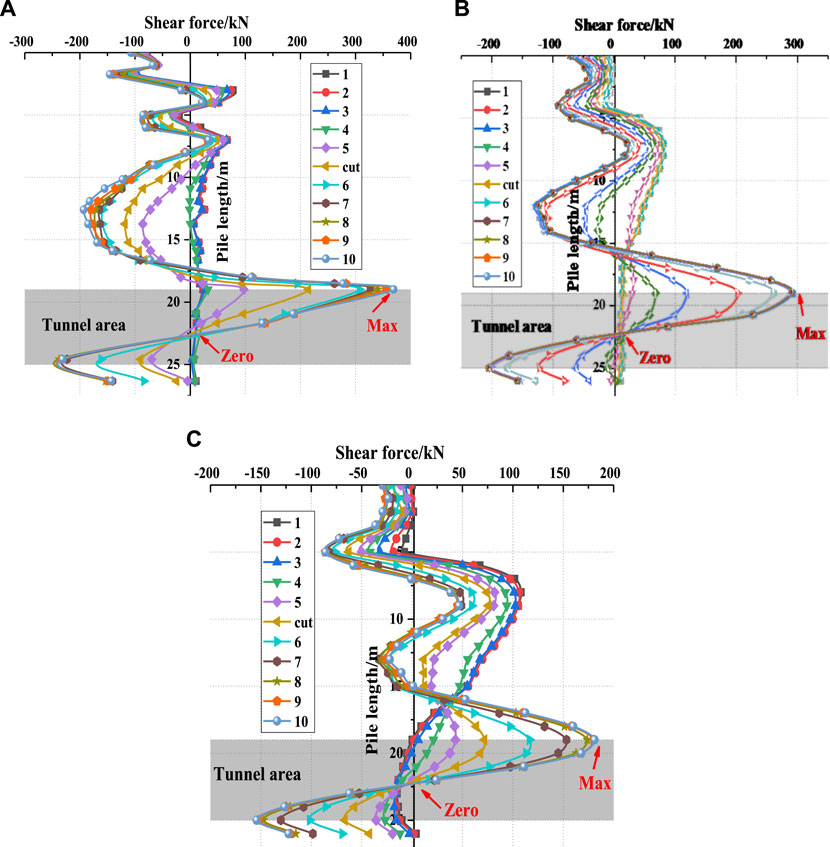
FIGURE 10. Shear force of piles at different distances: (A) L=12 m, θ=90° (B) L=16 m, θ=90° (C) L=20 m, θ=90°.
Figure 11 shows that the shear force at the top of the tunnel is still the largest at any angle. In this case, the maximum negative shear force is at the pile depth of 12 m when θ = 90°. Although there is a peak shear force at a pile depth of 12 m at 90°, it is not the maximum value. Taking the left pile as an example, when θ = 90°, 60°, and 45°, the peak shear forces are 367, 377, and 382 kN, respectively. The shear forces of the left and right piles have corresponding changes, but the peak value of the right pile is slightly smaller than that of the left pile. This is also because the shield machine first passes through the left pile, which has a greater impact on it.
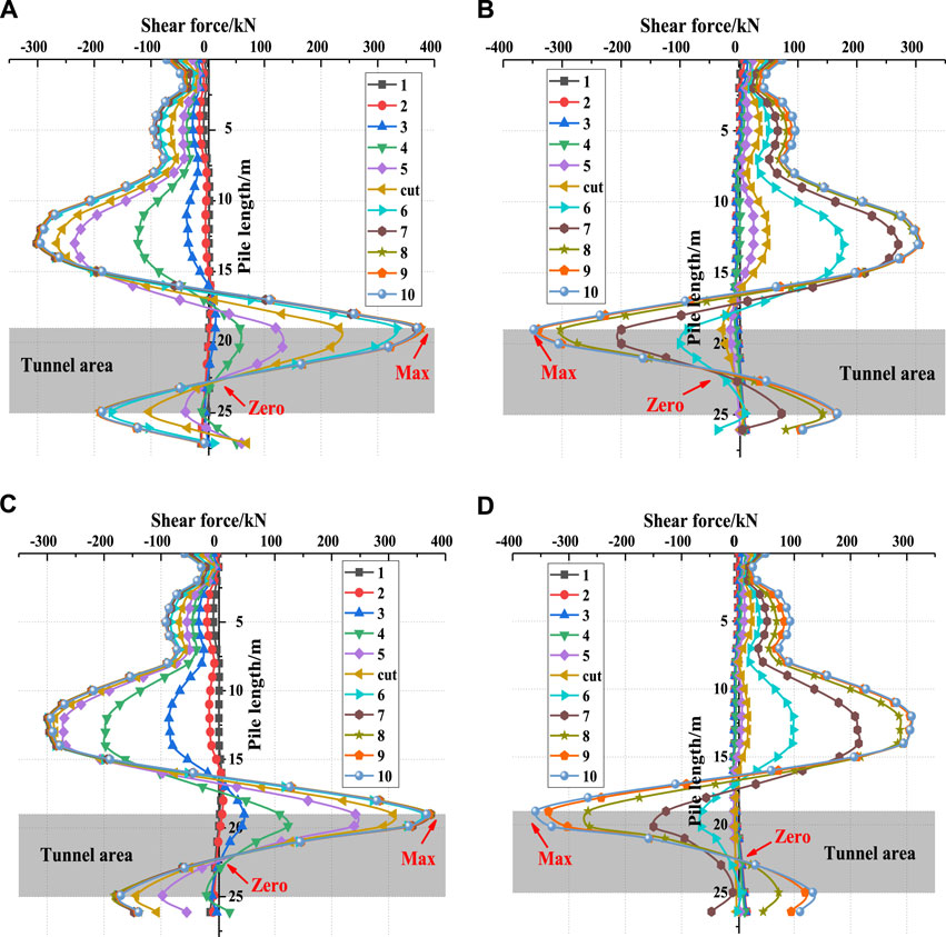
FIGURE 11. Shear force of piles at different angles: (A) d=3 m, left, θ=60° (B) d=3 m, right, θ=60° (C) d=3 m, left, θ=45° (D) d=3 m, right, θ=45°.
When θ = 60°, the peak shear force of the left pile occurs at the 9th excavation (r18); when θ = 45°, the peak shear force of the left pile occurs at the 8th excavation (r17). At that point, the horizontal distances between the shield machine and the left pile are 13.5 and 13.8 m, respectively. The shear forces then decrease slightly, which indicates that the influence of the shield machine on it is reduced.
Influence of the Displacement of the Underpinning Piles in Different Excavation Steps
Figure 12 shows that the lateral displacement of the pile reaches its maximum value in the last excavation step (r20), which is located at the central axis of the tunnel, similar to the bending moment. When L = 12 m, 16 m, and 20 m, the maximum values are 3.41, 3.28, and 3.19 mm, respectively. The piles above the tunnel area tend to approach the tunnel direction, and the maximum displacement of the piles above gradually moves upward along the piles as the pile spacing decreases.
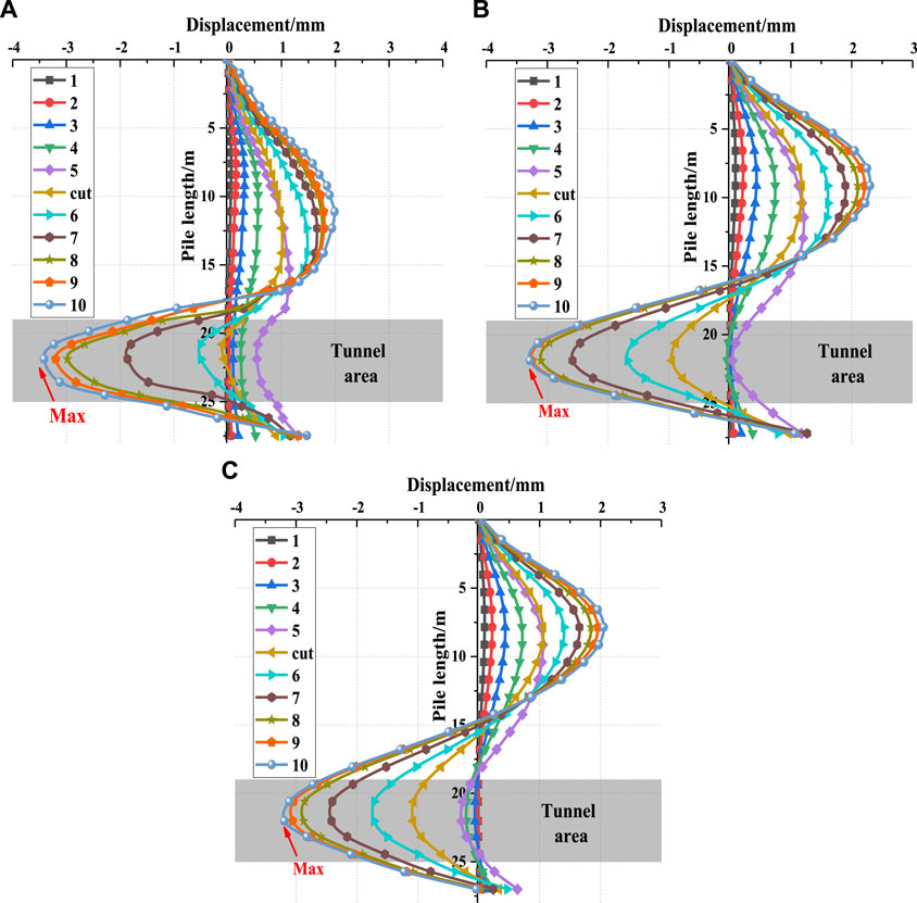
FIGURE 12. Displacement of piles at different distances: (A) L=12 m, θ=90° (B) L=16 m, θ=90° (C) L=20 m, θ=90°.
Figure 13 shows that when θ = 90°, 60°, and 45°, the maximum displacements (X-direction) are 3.41, 3.67, and 3.96 mm, respectively, which are located at the central axis of the left pile. The smaller the angle is, the more dangerous the situation gets. The trend of the change in the displacement of the right pile is the same as that of the left pile and is slightly smaller than that of the left pile.
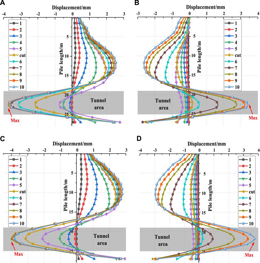
FIGURE 13. Displacement of piles at different angles: (A) d=3 m, left, θ=60° (B) d=3 m, right, θ=60° (C) d=3 m, left, θ=45° (D) d=3 m, right, θ=45°.
When θ = 60°, the maximum displacement of the left pile appears in selection step 8 (r17); when θ = 45°, the maximum displacement of the left pile appears in selection step 7 (r15), and the shield machine is 11.3 and 11.4 m away from the left pile, respectively. Although the displacement is subsequently reduced, the change is small, which corresponds to the final stabilization of the bending moment. The maximum value of the right pile is the last step of the selection. This is because the impact of the shield machine excavation of the tunnel and the removal of the existing pile on the underpinning pile ranges from large to small.
Conclusion
In this study, the influence of shield tunneling and cutting existing piles on underpinning piles is analyzed using 3D FEM modeling. The effects of the distance between the underpinning piles and the angle between the tunnel and underpinning beam on the bending moment of the underpinning pile are studied in detail. Some main conclusions are drawn as follows:
1) The bending moment of the underpinning pile decreases with increasing distance between the underpinning pile and the tunnel. Two anti-bending points are found in the pile bending curve, which appears near the pile head and the pile body. The maximum bending moment of the pile occurs at the depth of the central axis of the tunnel.
2) As the excavation advances, the bending moment of the pile corresponding to the central line of the tunnel first increases slowly and then rapidly tends to be stable. The maximum shear force of the underpinning pile occurs above the tunnel area at different distances and angles, and the maximum displacement occurs at the depth of tunnel central axis.
3) Through the analysis of underpinning piles at different angles, it is found that the influence range of the shield machine on the pile is approximately 11.5 m. When the shield machine is far from the pile, the bending moment, shear force, and displacement remain stable. Hence, field monitoring should be enhanced, and the excavation parameters of the shield machine should be timely adjusted to ensure safety and efficiency while in the influence range.
4) During tunnel excavation and pile cutting, the bending moment with a smaller angle is greater than that with a larger angle. Therefore, in pile design, more attention should be given to the piles with smaller intersection angles on both sides of the tunnel. Because the underpinning pile is mainly used to bear the vertical load of the upper bridge, the reinforcement is mainly calculated from the compression of the cross-section. However, the calculation of the bending capacity is also required in the design of piles according to the FEM calculation.
Data Availability Statement
The original contributions presented in the study are included in the article/Supplementary Material; further inquiries can be directed to the corresponding author.
Author Contributions
NW, YJ, and HD contributed to the numerical modeling work. DG and ZH helped to analyze the simulation results and provided guidance to the main conclusion of the study.
Funding
The research work is supported by the National Natural Science Foundation of China (Grant Nos. 51868021, 52168047), the Natural Science Foundation of Jiangxi Province (Nos. 20212BAB204012 and 20202BABL204051), and the State Key Laboratory of Performance Monitoring and Protecting of Rail Transit Infrastructure Foundation (No. HJGZ2021102).
Conflict of Interest
Author ZH was employed by the company Nanchang Rail Transit Group Limited Corporation.
The remaining authors declare that the research was conducted in the absence of any commercial or financial relationships that could be construed as a potential conflict of interest.
Publisher’s Note
All claims expressed in this article are solely those of the authors and do not necessarily represent those of their affiliated organizations, or those of the publisher, the editors, and the reviewers. Any product that may be evaluated in this article, or claim that may be made by its manufacturer, is not guaranteed or endorsed by the publisher.
References
Chen, H.-f., Yuan, D.-j., Wang, F., and Wang, M.-s. (2016). Study on Shield Cutting Parameters when Cutting Big Diameter Piles (In Chinese). China Civ. Eng. J. 49 (10), 103.
Chen, L. T., Poulos, H. G., and Loganathan, N. (1999). Pile Responses Caused by Tunneling. J. Geotech. Geoenviron. Eng. 125 (3), 207–215. doi:10.1061/(asce)1090-0241(1999)125:3(207)
Chen, S.-L., Lee, S.-C., and Wei, Y.-S. (2016). Numerical Analysis of Ground Surface Settlement Induced by Double-O Tube Shield Tunneling. J. Perform. Constr. Facil. 30 (5), 04016012. doi:10.1061/(asce)cf.1943-5509.0000732
Cheng, C. Y., Dasari, G. R., Chow, Y. K., and Leung, C. F. (2007). Finite Element Analysis of Tunnel-Soil-Pile Interaction Using Displacement Controlled Model. Tunn. Undergr. Space Technol. 22 (4), 450–466. doi:10.1016/j.tust.2006.08.002
Dimmock, P. S., and Mair, R. J. (2008). Effect of Building Stiffness on Tunnelling-Induced Ground Movement. Tunn. Undergr. Space Technol. 23, 438–450. doi:10.1016/j.tust.2007.08.001
Ding, L., and Xu, J. (2017). A Review of Metro Construction in China: Organization, Market, Cost, Safety and Schedule. Front. Eng. 4, 4–19. doi:10.15302/j-fem-2017015
Fu, D.-m. (2014). Model Test on Concrete Cutting Directly by Shield and Pile Foundation Cutting Technology. Tunn. Constr. 34 (5), 472.
Hong, Y., Soomro, M. A., and Ng, C. W. W. (2015). Settlement and Load Transfer Mechanism of Pile Group Due to Side-By-Side Twin Tunnelling. Comput. Geotechnics 64, 105–119. doi:10.1016/j.compgeo.2014.10.007
Huang, M., and Mu, L. (2012). Vertical Response of Pile Raft Foundations Subjected to Tunneling-Induced Ground Movements in Layered Soil. Int. J. Numer. Anal. Meth. Geomech. 36 (8), 977–1001. doi:10.1002/nag.1035
Huang, M., Zhang, C., and Li, Z. (2009). A Simplified Analysis Method for the Influence of Tunneling on Grouped Piles. Tunn. Undergr. Space Technol. 24 (4), 410–422. doi:10.1016/j.tust.2008.11.005
Jacobsz, S. W., Standing, J. R., Mair, R. J., Hagiwara, T., and Sugiyama, T. (2004). Centrifuge Modelling of Tunnelling Near Driven Piles. Soils Found. 44 (1), 49–56. doi:10.3208/sandf.44.49
Lee, C. J. (2013). Numerical Analysis of Pile Response to Open Face Tunnelling in Stiff Clay. Comput. Geotechnics 51, 116–127. doi:10.1016/j.compgeo.2013.02.007
Lee, C. J. (2012). Three-dimensional Numerical Analyses of the Response of a Single Pile and Pile Groups to Tunnelling in Weak Weathered Rock. Tunn. Undergr. Space Technol. 32, 132–142. doi:10.1016/j.tust.2012.06.005
Lee, G. T. K., and Ng, C. W. W. (2005). Effects of Advancing Open Face Tunneling on an Existing Loaded Pile. J. Geotech. Geoenviron. Eng. 131 (2), 193–201. doi:10.1061/(asce)1090-0241(2005)131:2(193)
Li, Z., Chen, Z., Wang, L., Zeng, Z., and Gu, D. (2021). Numerical Simulation and Analysis of the Pile Underpinning Technology Used in Shield Tunnel Crossings on Bridge Pile Foundations. Undergr. Space 6 (4), 396–408. doi:10.1016/j.undsp.2020.05.006
Liao, S.-M., Liu, J.-H., Wang, R.-L., and Li, Z.-M. (2009). Shield Tunneling and Environment Protection in Shanghai Soft Ground. Tunn. Undergr. Space Technol. 24 (4), 454–465. doi:10.1016/j.tust.2008.12.005
Lin, C.-g., Zhang, Z.-m., Wu, S.-m., and Yu, F. (2013). Key Techniques and Important Issues for Slurry Shield Under-passing Embankments: A Case Study of Hangzhou Qiantang River Tunnel. Tunn. Undergr. Space Technol. 38, 306–325. doi:10.1016/j.tust.2013.07.004
Liu, C., Zhang, Z., and Regueiro, R. A. (2014). Pile and Pile Group Response to Tunnelling Using a Large Diameter Slurry Shield - Case Study in Shanghai. Comput. Geotechnics 59, 21–43. doi:10.1016/j.compgeo.2014.03.006
Loganathan, N., Poulos, H. G., and Stewart, D. P. (2000). Centrifuge Model Testing of Tunnelling-Induced Ground and Pile Deformations. Géotechnique 50 (3), 283–294. doi:10.1680/geot.2000.50.3.283
Ma, L., and Wang, J. (2012). Technology of Pile Foundation Underpinning in Shield Tunnel of Xi'an Subway. Amm 204-208, 1445–1448. doi:10.4028/www.scientific.net/amm.204-208.1445
Marshall, A. M. (2012). Tunnel-Pile Interaction Analysis Using Cavity Expansion Methods. J. Geotech. Geoenviron. Eng. 138 (10), 1237–1246. doi:10.1061/(asce)gt.1943-5606.0000709
Meguid, M. A., and Mattar, J. (2009). Investigation of Tunnel-Soil-Pile Interaction in Cohesive Soils. J. Geotech. Geoenviron. Eng. 135 (7), 973–979. doi:10.1061/(asce)gt.1943-5606.0000004
Mirhabibi, A., and Soroush, A. (2012). Effects of Surface Buildings on Twin Tunnelling-Induced Ground Settlements. Tunn. Undergr. Space Technol. 29, 40–51. doi:10.1016/j.tust.2011.12.009
Marshall, M, and Robert, M (2011). "Tunneling beneath Driven or Jacked End-Bearing Piles in Sand." Can. Geotechnical J., 48(12), 1757–1771. doi:10.1139/t11-067
Ng, C. W. W., and Lu, H. (2014). Effects of the Construction Sequence of Twin Tunnels at Different Depths on an Existing Pile. Can. Geotechnical J. 51. doi:10.1139/cgj-2012-0452
Ng, C. W. W., Soomro, M. A., and Hong, Y. (2014). Three-dimensional Centrifuge Modelling of Pile Group Responses to Side-By-Side Twin Tunnelling. Tunn. Undergr. Space Technol. 43, 350–361. doi:10.1016/j.tust.2014.05.002
Pang, C. H., Yong, K. Y., and Chow, Y. K. (2005). Three-dimensional Numerical Simulation of Tunnel Advancement on Adjacent Pile foundation." Proc., Analysis of the Past and Lessons for the Future. Solak, T: Erdem, Y.
Park, K.-H. (2005). Analytical Solution for Tunnelling-Induced Ground Movement in Clays. Tunn. Undergr. Space Technol. 20 (3), 249–261. doi:10.1016/j.tust.2004.08.009
Soomro, M. A., Hong, Y., Ng, C. W. W., Lu, H., and Peng, S. (2015). Load Transfer Mechanism in Pile Group Due to Single Tunnel Advancement in Stiff Clay. Tunn. Undergr. Space Technol. 45, 63–72. doi:10.1016/j.tust.2014.08.001
Soomro, M. A., Ng, C. W. W., Liu, K., and Memon, N. A. (2017). Pile Responses to Side-By-Side Twin Tunnelling in Stiff Clay: Effects of Different Tunnel Depths Relative to Pile. Comput. Geotechnics 84, 101–116. doi:10.1016/j.compgeo.2016.11.011
Stulgis, R. P., Barry, B. E., and FrancisHarvey, S. J. (2004). Foundation Underpinning with Mini-Piles: ``A First'' in Guyana, South America. GeoSupport, 700–711. doi:10.1061/40713(2004)15
Verruijt, A., and Booker, J. R. (1996). Surface Settlements Due to Deformation of a Tunnel in an Elastic Half Plane. Géotechnique 46, 753–756. doi:10.1680/geot.1996.46.4.753
Wang, T., Tan, L., Xie, S., and Ma, B. (2018). Development and Applications of Common Utility Tunnels in China. Tunn. Undergr. Space Technol. 76, 92–106. doi:10.1016/j.tust.2018.03.006
Xu, K. J., and Poulos, H. G. (2001). 3-D Elastic Analysis of Vertical Piles Subjected to "passive" Loadings. Comput. Geotechnics 28 (5), 349–375. doi:10.1016/s0266-352x(00)00024-0
Yan, L., Wang, G., Chen, M., Yue, K., and Li, Q. (2018). Experimental and Application Study on Underpinning Engineering of Bridge Pile Foundation. Adv. Civ. Eng. 2018 (5), 1–13. doi:10.1155/2018/5758325
Yang, X.-j., Deng, F.-h., Wu, J.-j., Liu, J., and Wang, F.-q. (2009). Response of Carrying Capacity of Piles Induced by Adjacent Metro Tunneling. Min. Sci. Technol. (China) 19 (2), 176–181. doi:10.1016/s1674-5264(09)60033-8
Yao, A., Yang, X., and Dong, L. (2012). Numerical Analysis of the Influence of Isolation Piles in Metro Tunnel Construction of Adjacent Buildings. Procedia Earth Planet. Sci. 5, 150–154. doi:10.1016/j.proeps.2012.01.026
Yuan, D.-j., Wang, F., Dong, C.-w., Han, B., and Wang, M.-s. (2016). Study on New-Style Cutter for Shield Cutting Large-Diameter Reinforced Concrete Pile. China J. Highw. Transp. 29 (3), 89.
Keywords: shield tunnel excavation, cut piles, underpinning piles, 3D FEM modeling, bending moment
Citation: Wang N, Jiang Y, Geng D, Huang Z and Ding H (2022) Numerical Investigation of the Combined Influence of Shield Tunneling and Pile Cutting on Underpinning Piles. Front. Earth Sci. 10:896634. doi: 10.3389/feart.2022.896634
Received: 15 March 2022; Accepted: 22 June 2022;
Published: 18 July 2022.
Edited by:
Mohammed Y. Fattah, University of Technology, IraqCopyright © 2022 Wang, Jiang, Geng, Huang and Ding. This is an open-access article distributed under the terms of the Creative Commons Attribution License (CC BY). The use, distribution or reproduction in other forums is permitted, provided the original author(s) and the copyright owner(s) are credited and that the original publication in this journal is cited, in accordance with accepted academic practice. No use, distribution or reproduction is permitted which does not comply with these terms.
*Correspondence: Yalong Jiang, eWFsb25namlhbmdAd2h1LmVkdS5jbg==