 Meiben Gao1,2,3,4*
 Hua Zhang1
 Shenghua Cui4Zhongteng Wu2,3
 Ji Liu4
 Lixia Feng1Feng Zeng1Ning Li1Fujiang Chen1Tianbin Li4Yan Zhang4*
- 1School of Emergency Management, Xihua University, Chengdu, China
- 2Key Laboratory of Geohazard Prevention of Hilly Mountains, Ministry of Natural Resources, Fuzhou, China
- 3Fujian Key Laboratory of Geohazard Prevention, Fuzhou, China
- 4State Key Laboratory of Geohazard Prevention and Geoenvironment Protection, Chengdu University of Technology, Chengdu, China
Slope deformation and failure is an inevitable engineering problem in highway construction and operation in mountainous areas. Its essence is a continuous–discontinuous gradual failure process of slope under the action of unbalanced force. Slope deformation and failure mechanism is the basis and key content of its emergency treatment and comprehensive treatment. In this study, the continuous–discontinuous element method (CDEM) and finite difference method are used to analyze the deformation mechanism and support the effect of a scattered slope in the Biwei Expressway. The results showed that the change in the local geological environment caused by roadbed excavation leads to slope slippage along the surface and then pulls the upper rock mass gradually to produce slippage failure, resulting in the stability gradually decreasing. The mechanism is traction sliding–tensile cracking. The continuous–discontinuous element method can effectively simulate the formation process of the main and sub sliding planes during excavation and can better display the phenomenon of slope failure and gradual disintegration. The emergency disposal of the gravity anti-sliding retaining wall in front of the slope can effectively control further deformation and ensure temporary stability. In comprehensive treatment, step-type slope excavation, gravity anti-sliding retaining wall, and anchor frame beam are adopted to control the deformation and failure of slope and ensure long-term stability. The numerical simulation results are consistent with the actual results, which effectively explains the rationality of this study. The research results of this study can provide some reference for the emergency treatment and comprehensive treatment of slopes in mountainous areas and for the construction and operation of highways and other infrastructure in mountainous areas.
Highlights
1. The essence of slope instability is a continuous–discontinuous progressive deformation and failure process of slope under unbalanced mechanical conditions.
2. The slope has experienced a process of excavation–front part sliding–traction–back part sliding–gradual disintegration.
3. The novel CDEM method can effectively simulate the process of slope deformation, failure, and even disintegration.
4. The instability mechanism of the scattered slope in the LK0+063-LK0+400 section of the Biwei Expressway is traction sliding–tensile cracking.
Introduction
High and steep slopes are common along mountain highways due to subgrade excavation. Progressive slope movement or catastrophic slope failure of highway slopes could potentially cause severe safety problems to the construction workers and damages to the adjacent property with associated fatalities (Uribe-Etxebarria et al., 2005; Pantelidis, 2011; Shen et al., 2019a). Slope instability and its related hazards have always been the major issue that highway construction and management departments must face (Liang and Pensomboon, 2010; Zhang et al., 2021). Therefore, ensuring the stability of the slope is of vital significance to the safe construction and operation of highways in mountainous areas (Ju et al., 2011; Xue et al., 2015).
Some studies have systematically summarized the characteristics, influence factors, classification, failure mechanism, and mechanical model of slope based on a large number of slope engineering cases (Huang, 2009; Shen et al., 2019b; Zhang et al., 2019; Cui et al., 2021). Slope stability evaluation methods are also proposed (Griffiths and Lane, 1999; Zheng, et al., 2005; Kang et al., 2009). Huang (2009) investigated geological conditions, triggering factors, and mechanisms of some typical large-scale landslides in southwest China. Xue et al. (2018) analyzed the failure mechanism and stabilization of a basalt rock slide with weak layers. Wei et al. (2009) analyzed slope stability by the strength reduction and limit equilibrium methods. Li and Xu (2015) proposed a slope stability probability classification (SSPC) method to assess the stability of rock slopes in the Yunnan province of China. Marques and Lukiantchuki (2017) evaluated highway slope stability by numerical modeling. Before slope excavation or treatment, the deformation characteristics and failure mechanism should be evaluated (Ma et al., 2018; Xue et al., 2018; Zhao et al., 2019), while the stability and sliding force are usually first analyzed and calculated and then followed by the design of corresponding supporting measures (Singh et al., 2008; Zhao and Wu, 2014). Zhao and Wu (2014) designed bolt support for slope reinforcement based on the geographic information system. Yuan-cheng et al. (2019) adopted a two-stage support to the high fill slope. For complex slopes, the combined support system of the gravity anti-sliding retaining wall and anchor frame beam is widely used in mountainous slope treatment (Wei et al., 2012; Duan et al., 2014; Su et al., 2015), and there are many successful cases (Dong et al., 2010; Lin et al., 2020). The abovementioned research results have important reference significance for the further study of slope mechanism, emergency treatment, and comprehensive treatment. In fact, the essence of slope instability is a continuous–discontinuous process of gradual deformation and even disintegration of the slope under the condition of unbalanced mechanics (Li et al., 2009). It is advisable to study its deformation and failure mechanism from the perspective of continuous and discontinuous so as to provide a theoretical basis for its treatment.
The Biwei Expressway is located in the mountainous area of Southwest China, with a total length of about 125.5 km. The expressway is designed with a width of 21.5 m, a speed of 80 km/h, and four lanes in both directions. Due to the mountainous terrain and complex geological conditions along the route, during the excavation of subgrade in the LK0+063-LK0+400 section, the right-side high slope is deformed and partially collapsed, accompanied by many cracks. The internal structure is very loose, which may cause large-scale landslides at any time. The slope has undergone deformation and sliding several times and is now in a scattered state. A scattered slope is a slope undergoing a deformation–fracture–fragmentation process with a scattered structure. Its failure is a continuous–discontinuous process, which is the main difference from a normal landslide. However, there are few research studies on scattered landslides (Lai et al., 2005), especially the simulation and mechanism of the deformation–fracture–fragmentation process. In this study, combined with the actual slope, a continuous–discontinuous element method is used to analyze the deformation mechanism and the emergency response effect of the gravity-retaining wall and finally explore the comprehensive treatment effect by finite difference numerical simulation methods.
Overview of Studied Slope Engineering
Geological Conditions
The project area is situated in the Yunnan-Guizhou Plateau with a typical warm–humid monsoon climate. The precipitation in the region ranges from 793.1–984.5 mm, with an average annual precipitation of 851.6 mm. The subgrade slope is located in the northern slope of the Miaoling Mountains, with an elevation of 2000–2060 m, a height difference of about 60 m, and a slope angle of 20–25°. Surface water is generally developed with only streams. Groundwater mainly contains bedrock fissure water existing in the basalt structural plane and pore water in the Quaternary loose accumulation layer, and both of them are supplied by atmospheric precipitation. The landform type belongs to dissolution hills. Shrubs on the slope surface are well-developed. The rock strata in the area mainly consist of basalt and shale, dipping gently with little topographic relief. The Quaternary loose overburden is distributed in gentle slopes and valleys, which mainly comprise clay, silty clay, and gravel. The Luozhou–Hezhang anticline and Yadu faults are mainly geological structures in the area, and the Yadu faults are inactive nowadays. Seismic intensity is Ⅵ degree.
Deformation Characteristics of Slope
The umbrella pattern soil landslide is formed during subgrade excavation with a height of 13 m (See Figure 1). The high shear notch is developed on the front edge of the slope due to subgrade excavation. Under continuous creep, the soil in the shear notch area is squeezed out, slumped along the slope, and accumulated at the foot of the slope. Two sliding planes are developed in the slope, which is a step-shaped landslide. The main sliding body is 75 m long, 106 m wide, 4,654 m2 in area, 10 m in average thickness, and 5.1 × 10⁴ m3 in volume. The sliding direction is 195°, and the sliding angle is 25°. The shear outlet in front of the slope is at the elevation of 2015 m and the upper edge sliding wall at the elevation of 2051 m, resulting in a relative height difference of 36 m (See Figure 2). The sub-sliding body is located at the front of the slope, with an angle of 45°.
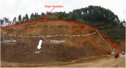
FIGURE 1. Panoramic view of the slope in the section between chainages LK0+063̴LK0+400.
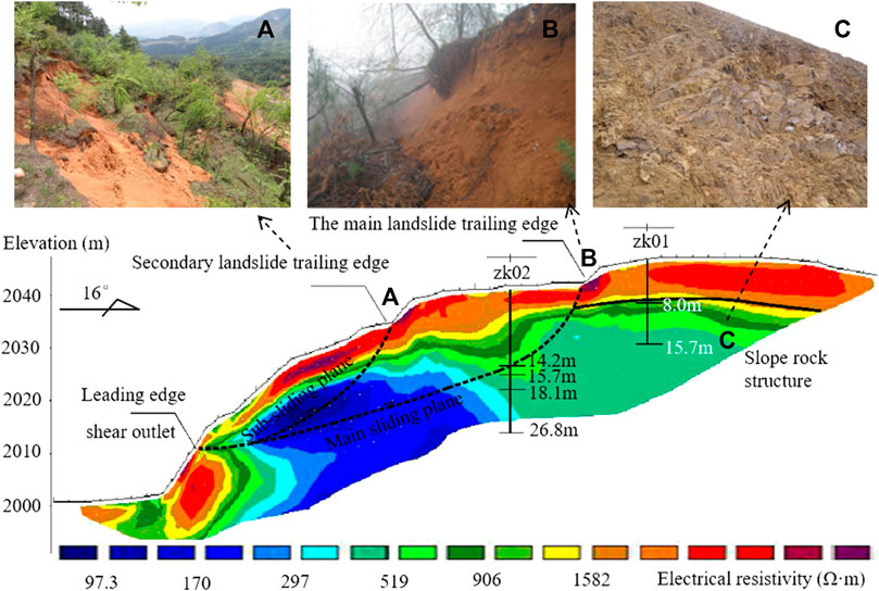
FIGURE 2. Interpretation results of the Werner section and deformation characteristics. (A): Secondary landslide trailing edge, (B): The main landslide trailing edge, (C): Slope rock structure.
The upper edge deformation of the slope is serious, the overall dislocation is 3–4 m (Figure 2B), and the tensile crack width is 2–3 m, forming the main sliding body (Figure 2). There is a secondary sliding body in the front part of the main sliding body. The angle of the secondary sliding plane is 45°. The sliding distance of the sub sliding body is 7–8 m, which is higher than that of the main sliding body (3–4 m).
The excavation profile has shown that the upper part of the slope is the Permian Longtan Formation comprising clay rock mixed with coal line and residual slope clay. The residual slope clay is in a plastic-soft to plastic state with a thickness of 7–8m, and the clay rock is completely weathered with a thickness of 1–10 m. The lower part of the slope is strongly weathered basalt, which is cut by bedding or crossing structural planes with a thickness of 5–10 cm, and the rock mass structure is very broken and fragmented (Figure 2C). The upper layer is seriously mixed with mud, mainly comprising fully weathered basalt mixed with soft plastic clay.
Moreover, according to the interpretation results of high-density electrical profiles and drilling data, the characteristics of the sliding body, sliding zone, and sliding bed are obtained.
(1) The sliding body mainly comprises cohesive soil with a small amount of gravel. Since, the slope mainly slides along the interface between clay and basalt, the upper part mainly contains clay with a loose structure. The lower part slides along the fully weathered basaltic weak zone, so the sliding body at the lower part of the east side is sandwiched with 3–5 m thick heavily weathered basalt. The rock mass has not been disturbed, and the original structural characteristics were kept to a certain extent. According to the interpretation of high-density electrical profiles, the apparent resistivity of this section is high (Figure 2), indicating loose sliding soil with low water content.
(2) The front edge of the sliding zone is buried 5–6 m deep and 0.5–2 cm thick, which is gray–white and gray–yellow soft plastic clay with good toughness. According to the core characteristics of the borehole (zk02), it is considered that the sliding zone is located 14.2 m underground, with a thickness of about 10 cm, and its composition is grayish–yellow clay. The west sliding zone is a black coal line with high water content, while the east sliding zone is a weak zone of fully weathered basalt with a thickness of 10 cm and very low water content. According to the interpretation of high-density electrical profiles, the water content along the sliding zone is high, especially near the shear outlet of the leading edge, and the apparent resistivity is quite different. The apparent resistivity isoline at the sliding zone displays a convex form (Figure 2).
(3) The sliding bed comprises grayish–yellow–grayish–black carbonaceous shale and strongly weathered basalt, cut by structural planes, and the rock mass is fractured. According to the interpretation of high-density electrical profiles, the apparent resistivity of the sliding bed is generally low, which indicates that the rock mass integrity of the sliding bed is poor and fractures are well-developed (Figure 2).
Formation Mechanism
Internal Factors: Rock and Soil Structure
According to the excavation results, the lower part of the slope is strongly weathered basalt with cataclastic structure, and the weak structural plane with a thickness of 5–10 cm is developed inside, with locally condensed calcareous basalt. Therefore, the overall performance of the rock property is poor. The upper part is claystone and carbonaceous shale with a coal line, dipping 150° with an angle of 16°. First, the inclination of the rock layer is opposite to the inclination of the slope, which is not conducive to its stability. Furthermore, the carbon shale belongs to soft rock, and the underlying strongly weathered basalt structure is broken, so their physical and mechanical properties are poor, and their contact interface is a weak structural plane. Under the action of groundwater and in situ stress field, the contact zone is muddy, which further reduces and weakens their physical and mechanical properties and will become a potential sliding surface under the long-term continuous creep. This unfavorable combination of structural planes and the underlying rock soil structure with weak structural planes are the internal causes of its instability.
Inducing Factors: Slope Instability Induced by Subgrade Excavation
In the early stage, subgrade excavation was carried out according to the slope ratio of 1:0.75–1:1, resulting in the height of leading-edge free space reaching 13 m and forming a favorable free space condition and high and steep slope. Moreover, the front edge of the slope belongs to the anti-sliding section, and excavation will seriously weaken the anti-sliding ability of the slope itself. Therefore, the excavation first provides a good free space condition for its sliding and second reduces the anti-sliding resistance, inducing the sliding deformation of the slope along the carbonaceous shale, tuffaceous basalt layer, and the interlayer dislocation zone and finally shearing out from the leading edge.
Simulation Analysis of Slope Mechanism Based on the CDEM
In fact, the essence of slope instability is a continuous–discontinuous deformation and failure process of the geological body under unbalanced mechanical conditions. The continuum–discontinuum element method (CDEM), proposed by Professor Li Shihai, is an explicit numerical method for solving highly fused meshes and particles based on the basic framework of generalized Lagrange equations. In this method, the continuum algorithm and discontinued algorithm are coupled, and the progressive failure process of the material is simulated through the fracture of the block boundary and inside the block. The numerical calculation model in the CDEM-BlockdyNA consists blocks and interfaces between blocks (Figure 3). Most of the finite element calculations involved appear in blocks. Blocks can comprise single or multiple finite elements, which are used to represent continuous physical characteristics of materials such as elasticity and plasticity. The common boundary between arbitrary blocks is called an interface. The calculation of the interface is mainly based on discrete elements, which is being used to express the discontinuous physical characteristics of materials such as displacement and impact. This method can not only simulate the elastic, plastic, damage, and fracture process of materials under static and dynamic loads but also simulate the movement, collision, flow, and accumulation process of broken granular materials, especially suitable for the whole process simulation of progressive instability and failure of slope deformation–fracture–fragmentation. Therefore, in this study, the CDEM method is used to simulate the whole process of scattered slope in the LK0+063-LK0+400 section of the Biwei Expressway to discuss its instability mechanism. The Mohr–Coulomb criterion and maximum tensile stress criterion were adopted for numerical calculation, and the calculation parameters are shown in Table 1.
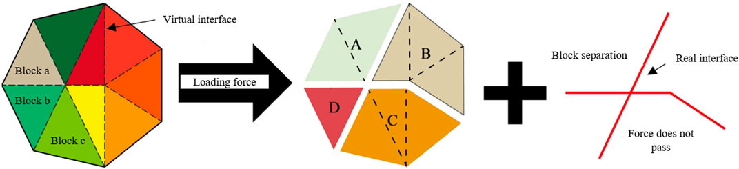
FIGURE 3. Block and interface diagram of the CDEM (modified from Feng et al., 2017).
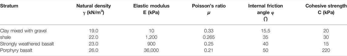
TABLE 1. Numerical modeling parameters.
Figure 4 shows the displacement nephogram of slope deformation and failure process at different time steps. According to Figure 4A, the excavation causes the front edge of the slope to form a good airport condition and begin to slide in the lower part of the slope, forming a sliding plane. Without support, the sliding plane gradually extends backward and cracks occur in the middle of the slope (Figure 4B). With the development of the sliding plane inside and on the upper part of the slope and the downward expansion of the crack in the middle of the slope, the sub-sliding plane is gradually formed (Figure 4C). The initial sliding plane develops further toward the rear edge and top of the slope, and the main slip surface gradually forms (Figure 4D). The numerical simulation results are consistent with the actual slope, indicating that the numerical simulation results can effectively reflect the formation process of the main sliding and sub-sliding plane during the excavation of the slope.
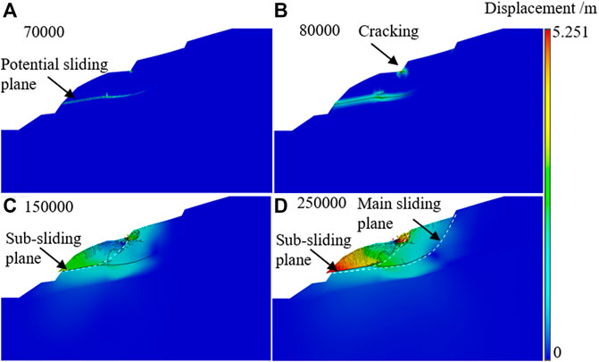
FIGURE 4. Displacement nephogram of slope (unit:m). (A): t = 70,000 steps, (B): t = 80,000 steps, (C): t = 1,50,000 steps, (D): t = 2,50,000 steps.
Figure 5 shows the maximum principal stress nephogram of slope deformation and failure process at different time steps. According to Figure 5A, the maximum principal stress of the slope gradually increases from top to bottom, which is generally controlled by the stress field of the slope. The principal stress direction near the surface is approximately vertical to the slope surface and gradually turns downward to the vertical direction. As the CDEM method is adopted, when the deformation between element meshes is too large and failure occurs, the block changes from a continuous state to a discontinuous state, and the related calculation units will disintegrate (as shown in the white area in Figure 5B). When the internal cracks of the slope are gradually formed, the related rock and soil bodies inside the slope are destroyed and disintegrated. Numerical calculation shows some white spots or areas, and connecting these white areas is the sliding plane of the slope (Figure 5B). Without support, the slope is further deformed and disintegrated, and finally, two sliding planes are formed (Fig. 5cd). At the same time, according to Figure 5D, there are many white areas in the sliding body, indicating that many cracks are developed in the sliding body. The sloping structure is very loose and broken, close to the state of granular, which is consistent with the actual situation.

FIGURE 5. Maximum principal stress nephoram (unit:Pa). (A): t = 70,000 steps, (B): t = 1,50,000 steps, (C): t = 2,00,000 steps, (D): t = 2,50,000 steps.
The excavation formed an exposed surface with a height of 13m, which destroyed the original equilibrium state of the slope and led to a sharp adjustment of the stress state of the slope. The lower rock and soil mass produced plastic yield, strain accumulation and unloading looseness, and slippage along the open surface. The sliding of the lower slope rock mass produces traction, which causes the upper rock mass to gradually slip and destroy, and the stability gradually decreases. When the tensile or shear plastic zone is extended to complete penetration, the slope will lose stability. The softening and lubrication of groundwater promote the occurrence and development of sliding. In conclusion, the mechanism of slope instability is the excavation process that weakens its anti-sliding force and induces the generation of continuous creep along the internal weak structural plane and the final shear out along the leading edge. The mechanism is traction sliding–tensile cracking.
Slope Emergency Treatment
The emergency disposal technology of slope (landslide) is mainly a quick and effective disposal technology for sliding body, which is a temporary disposal technology to prevent slope instability or further deformation of slope body and gain time for personnel evacuation and emergency deployment. It is an important step in the emergency disposal process of landslide geological disasters. Emergency rescue and disposal of landslide geological disasters is usually carried out on the basis of experience and in-site mapping without detailed investigation data, mainly including emergency rescue and disposal of dangerous situations and disasters, which is characterized by temporary rapidity, small disturbance, strong pertinence, and conservative scheme. At present, the slope of the K0+063∼ LK0+400 section of the Biwei Expressway is in constant creep deformation, and the rock and soil mass at the front shear outlet is extruded and collapsed, which is in an unstable state in the natural state. In case of adverse working conditions such as earthquakes and heavy rainfall, the landslide may lose its stability as a whole, endangering the construction and traffic safety of the National Way 326. In order to ensure the normal operation of roads and other infrastructure in the affected area and the normal construction of the Biwei Expressway and further provide time and space for comprehensive treatment of these slopes, this study discusses the effect of adopting mortar block stone gravity anti-slide retaining wall as an emergency disposal measure. The anti-sliding retaining wall has the characteristics of small disturbance and fast construction and can be used as a part of subsequent treatment projects. The top width of the retaining wall is 2 m, the wall height is 10 m, and the back slope is 1:0.25. The specific effect analysis is as follows:
Figure 6 shows the displacement trace and X-direction displacement diagram after the retaining wall is applied. According to Figure 6, after the retaining wall is applied, the slope still has a sliding trend toward the surface, but the displacement trace distribution is mainly concentrated on the potential sliding plane. Meanwhile, the sliding surface is not connected, indicating that the retaining wall as an emergency treatment measure can effectively restrain the further deformation of the slope and ensure temporary stability.
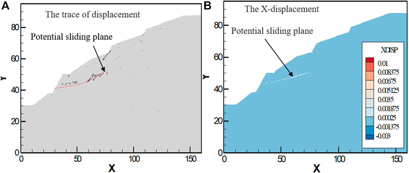
FIGURE 6. Displacement trace and X-direction displacement diagram after the retaining wall is applied. (A): The trace of displacement, (B): X-displacement.
In order to compare and analyze the deformation characteristics of the slope before and after the retaining wall was applied, 10 displacement monitored points were set on the sliding plane (see Figure 7 for specific layout) to monitor the displacement characteristics of the sliding plane under two situations. According to Figure 8A, before the retaining wall is applied, the general characteristic of the displacement of the measured points is that the displacement of the measured points at the front edge of the slope is larger than that at the rear edge, specifically M1> M2> M3> M4> M5> M6> M7> M8> M10 > M9. The monitoring results once again verify that the instability mechanism of the slope is traction sliding–tensile cracking. The displacement of the measured point M1 is the largest, with a magnitude of up to 4.5 m. The displacement of measured points M9 and M10 is the smallest, about 0.5 m. According to Figure 8B, after the emergency measures of the retaining wall are applied, the displacement of measured points on the sliding plane is generally controlled, and there is no large displacement measured point; especially the displacement of measured points M1, M2, and M3 on the front edge of landslide is effectively controlled. Among the ten measured points, the displacement of the measured point M4 is the largest, with a value of about 0.0014m, which is related to the development of the sub sliding plane. The measured point M4 is located at the junction of the main sliding plane and the sub sliding plane. In addition, there is a certain distance between M4 and the retaining wall, so its suppression effect has a certain loss, resulting in the displacement of measured point M4 being larger than that of other points. The comparative results show that the retaining wall can effectively control the further deformation of the slope, ensure the temporary stability of the slope, ensure the normal construction and passage of related roads, and then provide time and space for the comprehensive treatment of the slope, which is a good emergency treatment measure.
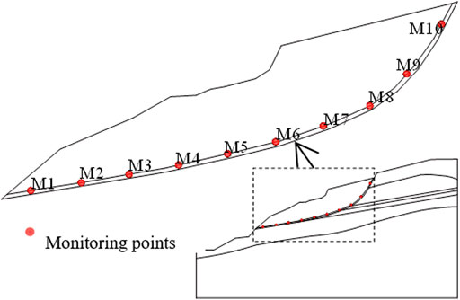
FIGURE 7. Layout of monitoring points.

FIGURE 8. Monitoring diagram of displacement of measuring points before and after applying the retaining wall. (O stands for the original state without supports, and the US stands for under support by gravity anti-sliding retaining well.). (A): None-support, (B): Gravity anti-sliding retaining wall supporting.
Slope Comprehensive Treatment and Effect Analysis
Slope Treatment Measures
Before treatment, the slope was in an unstable state. If the foot of the slope is further excavated according to the previous slope ratio (1:0.75–1:1), or there is heavy rainfall, the slope may be deformed and further destroyed, causing widespread instability.
Combined with the current situation of the slope and related construction conditions, the slope is re-excavated. The final excavation height of the slope is 57.55 m. The re-excavation is divided into six levels, and the first five levels are carried out according to the height of 10 m per level. The detailed treatment for each level is as follows: the slope cutting and gravity retaining wall are used for the first level, with a slope ratio of 1:0.75. The slope cutting and anchor frame beam are used for the second level, with a slope ratio of 1:1 and an anchor length of 5 m (spacing 3 m × 3 m). The slope cutting and an anchor cable frame beam are used for the third level, with a slope ratio of 1:1.25 and an anchor cable length of 18–25 m (spacing 4 m × 4 m). The slope cutting and anchor cable frame beam are used for the fourth level, with a slope ratio of 1:1.75 and an anchor cable length of 25–30 m (spacing 4 m × 4 m). The 5th–6th level slopes are cut at a ratio of 1:1.75 and supported by anchor frame beams with a length of 5–9 m (spacing 3 m × 3 m). For the anchor frame beam, the anchor rod adopts a φ25 ribbed steel bar, and the frame beam is 0.3 m × 0.3 m in size, and C25 concrete is used for cast-in-place construction. For the anchor cable frame beam, the anchor cable comprises six strands with φ15.2. The frame beam is 0.6 m × 0.6 m in size, and C25 concrete is used for cast-in-place construction. At the same time, intercepting drains are set at the outer edge of the slope and the load shedding platforms at all levels. The slope treatment profile is shown in Figure 9.
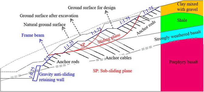
FIGURE 9. Treatment profile for the slope.
Effect Analysis
Based on the abovementioned analysis, the slope deformation can be effectively controlled by using the anti-sliding retaining wall as emergency support. In this case, with comprehensive support, the subsequent deformation of the slope and the deformation of the supporting structure belong to plastic failure. Fast Lagrangian Analysis of Continua 3D (FLAC3D) adopts an explicit Lagrangian algorithm and mixed-discrete partition technology, which can accurately simulate the plastic failure and flow of materials. It can simulate three-dimensional structural mechanical properties and plastic flow of soil, rock, and other materials. At the same time, the FLAC3D program also provides structural elements (such as anchor rods, anchor cables, etc.) to simulate slope reinforcement, making it easy to evaluate the support effect. Therefore, the FLAC3D program is selected to analyze the comprehensive support effect of the slope. Based on the existing deformation and failure characteristics of the slope, the slope model before and after treatment is established using the numerical software FLAC3D. Rock and soil mass is considered elastoplastic materials in PLAC3D, and the failure of material follows the Mohr–Coulomb yield criterion. At the same time, constraints are imposed on the model. Horizontal displacement constraints in the X direction are imposed on both sides of the model. Only vertical displacement is allowed, but horizontal displacement is not allowed. The upper surface is free, and the lower surface is fixed. Concerning the parameters in Table 1, numerical modeling is carried out for the slope before and after treatment. The modeling results are shown in Figures 10–12.
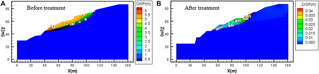
FIGURE 10. Slope displacement nephogram before and after treatment. (A): Before treatment, (B): After treatment.
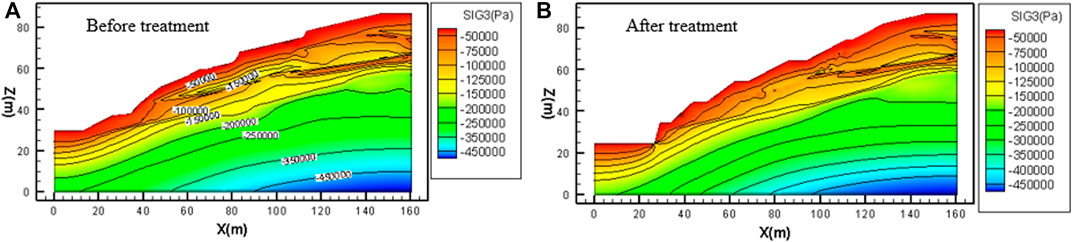
FIGURE 11. Minimum principal stress nephogram before and after treatment. (A): Before treatment, (B): After treatment.
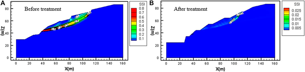
FIGURE 12. Maximum shear strain increment nephogram before and after treatment. (A): Before treatment, (B): After treatment.
The deformation of the slope does not converge before treatment (Figure 10A). Under the condition of sliding and squeezing at the trailing edge of the sliding body, the leading edge of the sliding body deforms most, forming a shear outlet, which will lead to sliding instability. If the treatment is carried out according to the changed design, there will be a small deformation at the upper part of the slope, with a value of 4 cm (Figure 10B), which can be effectively controlled. The comparison between the two conditions shows that slope deformation can be effectively controlled under the treatment.
Deformation and failure of the slope will lead to the change of principal stress in the slope. The soil stress concentration near the potential sliding plane at the bottom of the slope body is obvious before treatment (Figure 11A). After treatment according to the design change, the stress concentration at the bottom of the slope is eliminated, and the stress distribution is relatively uniform (Figure 11B).
The sliding plane or potential sliding plane of the slope can be reflected by the maximum shear strain increment. An obvious shear strain increment zone is formed at the bottom of the slope before treatment, that is, the sliding plane runs through the trailing edge of the slope from the leading edge, and the shear strain increment near the shear outlet of the leading edge and the trailing edge is the largest (Figure 12A). The sliding plane can be divided into the main sliding plane and secondary sliding plane along the shear strain increment zone. The main sliding plane runs through the bottom of the whole sliding body, and the secondary sliding plane is from the middle step to the front edge of the sliding body. After treatment, only the rear edge of the slope has a shear strain increment zone, and there is no obvious shear strain increment zone in the middle and lower part of the slope, which proves that the sliding plane is not completely penetrated (Figure 12B). The analysis of shear strain increment shows that the treatment can inhibit the formation of a slope sliding plane and ensure that the slope will not form through the sliding plane. The treatment effect is obvious.
In summary, numerical modeling results show that the slope was unstable before treatment and will slide after further deformation. After the comprehensive treatment mentioned above, the analysis of slope deformation, stress, and potential sliding plane shows that the slope deformation is effectively controlled. The stress is relatively uniform, and the formation of the sliding plane is restrained, indicating that the treatment effect is obvious. The slope will be in a stable state after treatment.
Conclusion
(1) The slope has experienced a process of excavation–front part sliding–traction–back part sliding– gradual disintegration. At present, the internal cracks of the slope are developed, making its structure very loose and broken in a scattered state. There are two sliding planes on the slope, and its current condition is unstable. If it is not been treated in time, further deformation will lead to its overall instability.
(2) The numerical simulation results of the CDEM reappear in the formation process of the main sliding plane and sub-sliding plane during the excavation of the slope, and the sub-sliding plane is formed earlier than the main sliding plane, revealing the instability mechanism of the slope is traction sliding–tensile cracking. It also shows that the CDEM is suitable for the whole process simulation of progressive instability and failure of slope deformation–fracture–fragmentation.
(3) Retaining the wall as an emergency treatment measure can effectively restrain the further deformation of the slope and ensure temporary stability.
(4) The comprehensive treatment with the gravity anti-sliding retaining wall + anchor cable (rod) frame beam can effectively control the deformation of the slope and ensure its long-term stability. In addition, it has the characteristics of flexible setting, cost-saving, and reliable technology and is widely used in slope prevention and control along with mountainous areas.
Data Availability Statement
The original contributions presented in the study are included in the article/Supplementary Material, further inquiries can be directed to the corresponding authors.
Author Contributions
MG and HZ were responsible for writing. JL provided engineering data and geophysical analysis of the slope. SC, ZW, and LF analyzed the deformation and failure characteristics of the slope. YZ, FZ, and NL conducted numerical simulation analysis, TL and FC were responsible for review and proofreading.
Funding
This research was supported by the National Natural Science Foundation of China (Nos. 42130719 and U19A20111), the Opening Foundation of Key Laboratory of Geohazard Prevention of Hilly Mountains, Ministry of Natural Resources (Fujian Key Laboratory of Geohazard Prevention) (Grant No. FJKLGH 2022K005), the National and Regional Research Center for The Belt and Road Initiative, National Ethnic Affairs Commission of China-Japan Emergency Management Research Center (RBYJ 2021–005), and the On-campus Talent Introduction Project at Xihua University (No. Z201055 & Z201125).
Conflict of Interest
The authors declare that the research was conducted in the absence of any commercial or financial relationships that could be construed as a potential conflict of interest.
Publisher’s Note
All claims expressed in this article are solely those of the authors and do not necessarily represent those of their affiliated organizations, or those of the publisher, the editors, and the reviewers. Any product that may be evaluated in this article, or claim that may be made by its manufacturer, is not guaranteed or endorsed by the publisher.
References
Cui, S., Pei, X., Jiang, Y., Wang, G., Fan, X., Yang, Q., et al. (2021). Liquefaction within a Bedding Fault: Understanding the Initiation and Movement of the Daguangbao Landslide Triggered by the 2008 Wenchuan Earthquake (Ms = 8.0). Eng. Geol. 295, 106455. 1-20. doi:10.1016/j.enggeo.2021.106455
Dong, J., Zhu, Y., Zhou, Y., and Ma, W. (2010). Dynamic Calculation Model and Seismic Response for Frame Supporting Structure with Prestressed Anchors. Sci. China Technol. Sci. 53 (7), 1957–1966. doi:10.1007/s11431-010-3241-z
Duan, J., Yan, Z.-x., Guo, R.-j., and Ren, Z.-h. (2014). Response Analysis of Frame Supporting Structure of Slope under Harmonic Vibration. Math. Problems Eng. 2014, 1–13. doi:10.1155/2014/603863
Feng, C., Li, S. H., Hao, W. H., and Ge, W. (2017). Numerical Simulation for Penetrating and Blasting Process of EPW Based on CDEM. J. Vib. Shock 36 (13), 11–18. 26(In Chinese with English abstract). doi:10.13465/j.cnki.jvs.2017.13.002
Griffiths, D. V., and Lane, P. A. (1999). Slope Stability Analysis by Finite Elements. Géotechnique 49 (3), 387–403. doi:10.1680/geot.1999.49.3.387
Ju, N., Zhao, J., Huang, R., and Duan, H. (2011). Dynamic Design and Construction of Highway Cut Slopes in Huangshan Area, China. J. Mt. Sci. 8 (2), 154–165. doi:10.1007/s11629-011-2113-8
Kang, G.-C., Song, Y.-S., and Kim, T.-H. (2009). Behavior and Stability of a Large-Scale Cut Slope Considering Reinforcement Stages. Landslides 6 (3), 263–272. doi:10.1007/s10346-009-0164-5
Lai, Z. S., Wu, J. Y., and Ma, J. X. (2005). Study on Excavation Parameters for High Rock Slope of Scattered Structure. Chin. J. Rock Mech. Eng. 24 (12), 2183–2187. (In Chinese with English abstract). doi:10.3321/j.issn:1000-6915.2005.12.030
Li, S. H., Liu, T. P., and Liu, X. Y. (2009). Analysis Method for Landslide Stability. Chin. J. Rock Mech. Eng. 28 (s2), 3309–3324. (In Chinese with English abstract). doi:10.3321/j.issn:1000-6915.2009.z2.004
Li, X. Z., and Xu, Q. (2015). Application of the SSPC Method in the Stability Assessment of Highway Rock Slopes in the Yunnan Province of China. Bull. Eng. Geol. Environ. 75 (2), 551–562. doi:10.1007/s10064-015-0792-z
Liang, R., and Pensomboon, G. (2010). Multicriteria Decision-Making Approach for Highway Slope Hazard Management. J. Infrastruct. Syst. 16 (1), 50–57. doi:10.1061/(asce)1076-0342(2010)16:1(50)
Lin, Y.-l., Li, Y.-x., Zhao, L.-h., and Yang, T. Y. (2020). Investigation on Seismic Response of a Three-Stage Soil Slope Supported by Anchor Frame Structure. J. Cent. South Univ. 27 (4), 1290–1305. doi:10.1007/s11771-020-4367-1
Ma, G., Hu, X., Yin, Y., Luo, G., and Pan, Y. (2018). Failure Mechanisms and Development of Catastrophic Rockslides Triggered by Precipitation and Open-Pit Mining in Emei, Sichuan, China. Landslides 15 (7), 1401–1414. doi:10.1007/s10346-018-0981-5
Marques, G. S., and Lukiantchuki, J. A. (2017). Evaluation of the Stability of a Highway Slope through Numerical Modeling. DYNA 84 (200), 121–128. doi:10.15446/dyna.v84n200.53850
Pantelidis, L. (2011). A Critical Review of Highway Slope Instability Risk Assessment Systems. Bull. Eng. Geol. Environ. 70 (3), 395–400. doi:10.1007/s10064-010-0328-5
Runqiu, H. (2009). Some Catastrophic Landslides since the Twentieth Century in the Southwest of China. Landslides 6 (1), 69–81. doi:10.1007/s10346-009-0142-y
Shen, T., Wang, Y.-s., Luo, Y.-h., Xin, C.-c., Liu, Y., and He, J.-x. (2019b). Seismic Response of Cracking Features in Jubao Mountain during the Aftershocks of Jiuzhaigou Ms7.0 Earthquake. J. Mt. Sci. 16 (11), 2532–2547. doi:10.1007/s11629-019-5570-0
Shen, T., Wang, Y., Huang, Z., Li, J., Zhang, X., Cao, W., et al. (2019a). Formation Mechanism and Movement Processes of the Aizigou Paleolandslide, Jinsha River, China. Landslides 16 (2), 409–424. doi:10.1007/s10346-018-1082-1
Singh, T. N., Gulati, A., Dontha, L., and Bhardwaj, V. (2008). Evaluating Cut Slope Failure by Numerical Analysis-A Case Study. Nat. Hazards 47 (2), 263–279. doi:10.1007/s11069-008-9219-5
Su, H., Hu, J., and Yang, M. (2015). Evaluation Method for Slope Stability under Multianchor Support. Nat. Hazards Rev. 16 (4), 04014034. doi:10.1061/(ASCE)NH.1527-6996.0000171
Uribe-Etxebarria, G., Morales, T., Uriarte, J. A., and Ibarra, V. (2005). Rock Cut Stability Assessment in Mountainous Regions. Environ. Geol. 48 (8), 1002–1013. doi:10.1007/s00254-005-1323-1
Wei, W. B., Cheng, Y. M., and Li, L. (2009). Three-dimensional Slope Failure Analysis by the Strength Reduction and Limit Equilibrium Methods. Comput. Geotechnics 36 (1-2), 70–80. doi:10.1016/j.compgeo.2008.03.003
Wei, Z., Yin, G., Wang, J. G., Wan, L., and Jin, L. (2012). Stability Analysis and Supporting System Design of a High-Steep Cut Soil Slope on an Ancient Landslide during Highway Construction of Tehran-Chalus. Environ. Earth Sci. 67 (6), 1651–1662. doi:10.1007/s12665-012-1606-2
Xue, D., Li, T., Wei, Y., and Gao, M. (2015). Mechanism of Reactivated Badu Landslide in the Badu Mountain Area, Southwest China. Environ. Earth Sci. 73 (8), 4305–4312. doi:10.1007/s12665-014-3714-7
Xue, D., Li, T., Zhang, S., Ma, C., Gao, M., and Liu, J. (2018). Failure Mechanism and Stabilization of a Basalt Rock Slide with Weak Layers. Eng. Geol. 233, 213–224. doi:10.1016/j.enggeo.2017.12.005
Yuan-cheng, G., Hao, D., Yun-hua, L., Qing, Q., and Jun-wei, J. (2019). Stability Analysis and Application of Two-Stage Support on the High Fill Slope. J. Phys. Conf. Ser. 1168, 022064. doi:10.1088/1742-6596/1168/2/022064
Zhang, Y.-h., Wang, Y.-s., Wang, W.-s., Liu, J., and Yuan, L.-l. (2019). Zircon U-Pb-Hf Isotopes and Mineral Chemistry of Early Cretaceous Granodiorite in the Lunggar Iron Deposit in Central Lhasa, Tibet Y, China. J. Cent. South Univ. 26 (12), 3457–3469. doi:10.1007/s11771-019-4266-5
Zhang, Y., He, Z., Tian, H., Huang, X., Zhang, Z., Liu, Y., et al. (2021). Hydrochemistry Appraisal, Quality Assessment and Health Risk Evaluation of Shallow Groundwater in the Mianyang Area of Sichuan Basin, Southwestern China. Environ. Earth Sci. 80 (17576), 1–16. doi:10.1007/s12665-021-09894-y
Zhao, J., and Wu, H. (2014). Study on the Slope Bolt Support Design Based on GIS. Tociej 8 (1), 458–462. doi:10.2174/1874149501408010458
Zhao, L., Li, D., Tan, H., Cheng, X., and Zuo, S. (2019). Characteristics of Failure Area and Failure Mechanism of a Bedding Rockslide in Libo County, Guizhou, China. Landslides 16, 1367–1374. doi:10.1007/s10346-019-01188-6
Keywords: slope, deformation mechanism, CDEM, excavation, sliding-tensile cracking
Citation: Gao M, Zhang H, Cui S, Wu Z, Liu J, Feng L, Zeng F, Li N, Chen F, Li T and Zhang Y (2022) Investigation on Deformation Mechanism and Treatment Effect of a Scattered Slope Based on Continuum–Discontinuum Element Method and Finite Difference Method. Front. Earth Sci. 10:894923. doi: 10.3389/feart.2022.894923
Received: 12 March 2022; Accepted: 13 April 2022;
Published: 13 May 2022.
Edited by:
Yunhui Zhang, Southwest Jiaotong University, ChinaReviewed by:
Meng Zhao, Chengdu University, ChinaTong Shen, Henan University of Urban Construction, China
Dongsheng Wu, Jinan University, China
Copyright © 2022 Gao, Zhang, Cui, Wu, Liu, Feng, Zeng, Li, Chen, Li and Zhang. This is an open-access article distributed under the terms of the Creative Commons Attribution License (CC BY). The use, distribution or reproduction in other forums is permitted, provided the original author(s) and the copyright owner(s) are credited and that the original publication in this journal is cited, in accordance with accepted academic practice. No use, distribution or reproduction is permitted which does not comply with these terms.
*Correspondence: Meiben Gao, Z2FvbWJAbWFpbC54aHUuZWR1LmNu; Yan Zhang, emh5bHIxOTg4QDEyNi5jb20=