 Chen Zhao
 Xiuquan Hu
 Jianghan Li
 Chi Yi
 Jieyi Li
 Zhipeng Niu
95% of researchers rate our articles as excellent or good
Learn more about the work of our research integrity team to safeguard the quality of each article we publish.
Find out more
ORIGINAL RESEARCH article
Front. Earth Sci. , 27 April 2022
Sec. Economic Geology
Volume 10 - 2022 | https://doi.org/10.3389/feart.2022.892902
This article is part of the Research Topic The Relationship between Petroleum Accumulation and Mineralization in Sedimentary Basins View all 19 articles
The exploration of deep-water submarine fan reservoirs has become a prominent research area for hydrocarbon discovery and recovery. However, the high operational costs render efficient exploration of this type of reservoir crucial, and the pivotal foundation lies in studying reservoir architectures. A case study of deep-water submarine fans in the Albacora Leste oilfield in Brazil is presented along with a characterization of the underground reservoir architecture based on well-log and seismic model fitting. A sedimentary microfacies distribution model is systematically established for each reservoir based on a detailed stratigraphic framework with a well-seismic joint characterization method and various types of data (e.g., geological, well-log, and seismic data). The results are as follows: the sedimentary microfacies of the deep-water submarine fans in the study area can be subdivided into tongue-shaped-lobe, muddy-channel, sandy-channel, and contourite deposits. Owing to data abundance and quality constraints, the architecture of the target layer in the study area was characterized based on Level 4 architectural elements. The AB120 Reservoir consisted of three complex channels (I, II, and III) and two tongue-shaped complex lobes (I and II). Complex channels I and III were the first and last to be deposited, respectively, and complex lobe I was deposited earlier than complex lobe II. Complex channels II and III supply complex lobes I and II, respectively. Vertically, complex lobe II was composed of three single lobes formed at different stages, the youngest of which was distributed over the largest area. Complex lobe II has already been drilled and is currently under development. However, complex lobe I has not yet been developed. This study has great practical significance for the effective development of deep-water submarine-fan reservoirs in this area and is of considerable theoretical significance for the advancement of deep-water sedimentology.
Deep-water submarine fans are rich in oil and gas resources. High exploration and development costs and immature processing techniques prevented previous deep-water exploration efforts from receiving serious attention. As a result, global deep-water oil and gas resource development levels are low, and the potential amount of resources available is huge. Statistical data show that untapped oil and natural gas resources worldwide exceed 300 × 108 tons and 34 × 1012 m3, respectively, demonstrating immense potential for discovery and recovery (Walker, 1978; Weimer and Link, 1991; Fetter et al., 2008; Yin, 2018; Liu et al., 2020; Wang L. et al., 2020; Gu et al., 2021; Li et al., 2021). Continual advancement in deep-water sandy oil and gas exploration theories and technologies, such as high-resolution three-dimensional (3D) seismic analysis and deep-sea drilling platforms, has allowed deep-water sedimentological research to attract growing attention worldwide (Gervais et al., 2006; Mann et al., 2007; Bhuiyan and Hossain, 2020; Gao et al., 2020; Sun et al., 2020; Wang W. et al., 2020; Tang et al., 2021; Zhao et al., 2021). Currently, deep-water submarine fans constitute an important area for hydrocarbon exploration and development.
The genetic mechanism of deep-water submarine fan deposition is very complex, including the transport process of turbidity currents, debris flows, and sliding-collapse blocks. These mechanisms form complex and diverse submarine fan deposition types e.g., turbidity fans which are a type of deep-water submarine fan (Zhang and Wu, 2019; Sajid et al., 2020). Romans et al. (2010) conducted an in-depth investigation on the evolution of the deep-water stratigraphic architecture in the Magallanes Basin in Chile and analyzed the relationship between architectural changes and intrinsic tectonic evolution. Zhao et al. (2012) introduced a technique to characterize deep-water turbidite channel reservoir architectures based on integrated well-log and seismic data. Following an investigation of a particular architectural model of turbidite channel systems, Liu et al. (2013) identified and subsequently established corresponding architectural models for different types of channel systems and analyzed their control factors, evaluation criteria, and spatial distribution patterns. Lin et al. (2014) examined the distribution patterns of composite sand bodies in the turbidite channels. Zhang et al. (2015) discussed variations in the physical properties of reservoirs in sinuous deep-water channel systems and their relevant control mechanisms. They identified rock texture, lithofacies, and channel architecture as the primary controlling factors responsible for variations in reservoir quality in sinuous deep-water channel systems. According to the water depth measurement data, Reimchen et al. (2016) determined the statistical relationship between the cross-sectional asymmetry and the plane shape of the bent curved channel, and determined the relationship between the geometric shape and the plane shape of the submarine channel. Using unsupervised neural network (UANN) to integrate artificial intelligence (AI) and fluid identification of seismic attributes, Obafemi et al. (2020) studied the structural characteristics of deep-water turbidite channels and submarine fan lobes of deep-water oil and gas reservoirs in Frem Oilfield, Niger Delta. Recent published research has focused primarily on turbidite channels and provides an in-depth examination of their architectural characteristics, structural models, and control factors. In contrast, attention to turbidite lobes remains inadequate, with the investigation of the architectural characteristics of their reservoirs still in its incipient stages. In this study, guided by a detailed stratigraphic framework, a sedimentary microfacies distribution model was systematically established for each reservoir in the study area through characterization based on integrated data (e.g., geological, well-log, and seismic data). With a focus on both turbidite channels and turbidite lobes, reservoir architectures are characterized in detail based on well-log and seismic model fitting.
The Campos Basin is located 120 km off the coast of Rio de Janeiro in southeast Brazil, and the basin is distributed both onshore and offshore, is approximately 500 km long and 150 km wide, and is the most prolific oil- and gas-producing basin in the country. Basement heights perpendicular to the continental margin separate the Campos Basin from its adjoining basins. Specifically, the Campos Basin is separated from the Espirito Santo Basin by the Victoria High in the north, and from the Santos Basin by the Cabo Frio High in the south (Figure 1). The tectonic evolution of the Campos Basin has undergone four stages: the pre-rift, rift, transitional, and drift stages. The Campos Basin is a typical Atlantic passive continental margin basin formed by the separation of South America from Africa. Sediments are deposited in the South Atlantic crust and become thicker eastward, forming a sedimentary wedge. (Bybee, 2006; Ma et al., 2011; Kang et al., 2018; Lima and De Ros., 2019; Pandolpho et al., 2021).
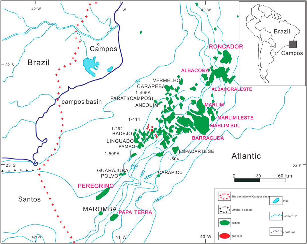
FIGURE 1. Location of the Campos Basin and the distribution of the main oil and gas fields.
Three main sedimentary sequences have developed in the Campos Basin: the continental sequence of the rift stage, the rock-salt sequence of the transitional stage, and the marine sequence of the drift stage. There are three Oligocene-Miocene formations in the study area, which, from the bottom up, are CRT, Marlim, and Albacora. Albacora Formation was examined in the present study, and for simplicity, it was divided into six layers: Sq-AB250, Sq-AB210, Sq-AB140, Sq-AB120, Sq-AB110, and Mio400. Sq-AB120 is considered a primary example for illustration purposes and was further subdivided into three stratigraphic units: Sq-AB120-1, Sq-AB120-2, and Sq-AB120-3. In the western part of the study area, the stratum thickness of the target layer tends to become thinner from north to south; in the eastern part of the study area, the stratum thickness tends to become thicker from north to south; in the northern part of the study area, the stratum thickness changes in equal proportions from west to east, and there is a thinning trend. In the southern part of the study area, the stratum thickness varies unevenly from west to east. Overall, from southwest to northeast, the target layer appears to be thicker in the central region and thins out at both ends.
Based on a detailed stratigraphic framework, this study thoroughly characterized the single-well, sectional, and planar perspectives of the reservoir by analyzing the sedimentary microfacies types and their spatial distribution patterns using well-seismic technical methods and different types of data (e.g., geological, well-log, and seismic data). The types and characteristics of the sedimentary microfacies were identified with detailed analysis methods including: core description results, rock-electricity calibration, well-seismic calibration, determining the single-well interpretation and the sectional distribution patterns through integrated well-log and seismic sections along different directions, selecting the limit values of the seismic attribute corresponding to the sandstone facies, and estimating the macroscopic morphology of the sedimentary bodies with a truncation procedure. The results facilitate architectural characterization using a hierarchical system based on the abundance and quality of the data for the study area. Subsequently, a sedimentary model was used to characterize the single-well and sectional architecture of different sedimentary microfacies by identifying the boundaries of the architectural elements. Finally, the architectural elements were connected according to their geometrical relationships, and the detailed two-dimensional (2D) depiction of the architectural elements was completed.
The study area was 19 km2. A detailed core description was provided for seven coring wells in the study area. A comprehensive histogram was plotted using the coring well combined with logging data, and a rock-electric model was established. A single-well phase interpretation was conducted for the remaining 53 uncoring wells. The study area was fully covered with 3D seismic data with good volume quality. The imaging of the target layer was good, and the signal-to-noise ratio was high, which can adequately fulfil the requirements of this reservoir architecture study. The fine seismic interpretation and tracking of three small layers of the AB120 Formation was conducted, with the interpretation accuracy reaching 10*10. Various seismic attributes were extracted including amplitude, coherence, and impedance. The correlation between mudstone thickness, sandstone thickness, sand-ground ratio, and other parameters and seismic attributes was calculated, and the corresponding limit value were determined for the sandstone facies. The sedimentary facies plan of the AB120 Formation was drawn based on well-seismic combination. The hierarchy of architecture characterization of the whole area was determined according to the number of coring wells, logging data and seismic data quality. Based on the detailed characterization of seismic profiles, single-well Level 3 architecture was characterized through lateral transformation features, seismic amplitude changes, sand body thickness changes. The architecture unit boundaries were identified according to the geometric relationships between each unit.
Sedimentary environments and conditions govern sand bodies in terms of their level of development, spatial distribution, and internal structure. Sand bodies that formed in different sedimentary environments have different reservoir qualities. Sedimentary microfacies analysis can unequivocally reveal the macroscopic distribution of sand bodies.
Provenance is an important tool for judging the distribution of sedimentary facies and sand body dispersion systems. The provenance of deep-water submarine fans can be roughly determined using channel direction (Li C. et al., 2017). The downcutting energy of the channel was strong in the western part of the study area, and the channel was distributed in a northwestern direction. In the central part of the study area, the downcutting capacity is weak to non-existent, and the channel is distributed in a northeastern direction. Constructing seismic profiles is also an important means to study provenance, and regression and overpass can indicate source direction (Pu et al., 2003; Liang et al., 2019). The overlapping points on the seismic profile of the combined well (Figure 6) show that the sand body receded in a northwestern direction, and the longitudinal extension scale of the sand body gradually decreased from bottom to top. Therefore, the provenance was from the northwest part of the study area. This agrees with the findings of Kang et al. (2018).
The AB120 Reservoir contains various types of sedimentary microfacies. In-depth analysis of the core, well-log, and seismic data revealed the presence of four main sedimentary microfacies in this reservoir: tongue-shaped lobes, muddy channels, sandy channels, and contourite deposits.
The tongue-shaped lobes display a reverse rhythm, with a composition that transitions upward from thinly interbedded sandstone and mudstone to massive fine sandstone. Observation of the well-logs shows a typical funnel-shaped natural gamma ray (GR) pattern, low density, large arrival-time difference, and high electrical resistance in the reservoir segment, suggesting good reservoir quality. The seismic response of the tongue-shaped bodies was characterized by distinctly high-amplitude and continuous reflections (Figure 2).
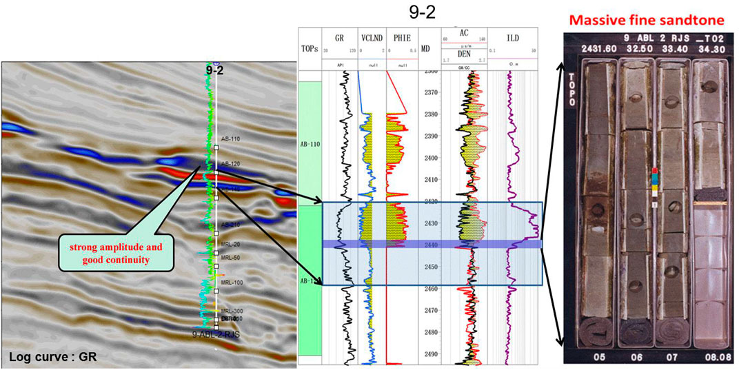
FIGURE 2. Seismic response, logging and lithologic characteristics of the tongue-shaped lobes in AB120 reservoir.
No cores were retrieved from the muddy channels in the study area. Analysis of the extracted 3D root-mean-square (RMS) amplitude map for the AB120 Formation revealed distinct connections between the channels and tongue-shaped lobes in the western part of the study area, corresponding to low-amplitude reflections. This suggests that the channels were filled with muddy sediment. A section perpendicular to the source direction was taken at the suspected location where the channels had developed to confirm this. An analysis of this section of the AB120 Formation reveals a vertical low-amplitude, imbricate reflection structure, which is characteristic of a typical cut, and a stacked muddy channel complex (Figure 3).
FIGURE 3. Seismic response characteristics of the muddy channels.
The sandy channels primarily consist of massive fine sandstone and display a positive rhythm. Specifically, from the bottom up, they are composed of mass-transport deposits, massive fine sandstone, fine sandstone intercalated with thinly interbedded sandstone and mudstone, and finally thinly interbedded silty sandstone and mudstone. The sandy channels were density-flow deposits. Observation of the well-logs showed a typical bell-shaped natural GR pattern, low density, large arrival-time difference, and high electrical resistance in the reservoir layer, suggesting good reservoir quality. In the seismic section, the sandy channels appear U- or V-shaped, with short axes and wavy reflectors filled with moderate-to high-amplitude seismic facies (Figure 4).
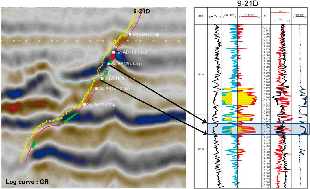
FIGURE 4. Well-log and seismic response characteristics of the sandy channels.
The core data for the AB120 Reservoir revealed the presence of numerous thinly interbedded sandstone and mudstone. The sandstone lithology is mainly silty fine sandstone and is likely a product of frequent contourite activity. The cross-well section in Figure 6 shows the presence of contourite deposits at the top of AB120 Reservoir. This reservoir layer is approximately 2 m thick and is distributed transversely in a stable manner (Figure 5). Examination of the reservoir parameters interpreted from the well-logs shows that the contourite deposits are inferior to the tongue-shaped lobes in terms of their physical properties.
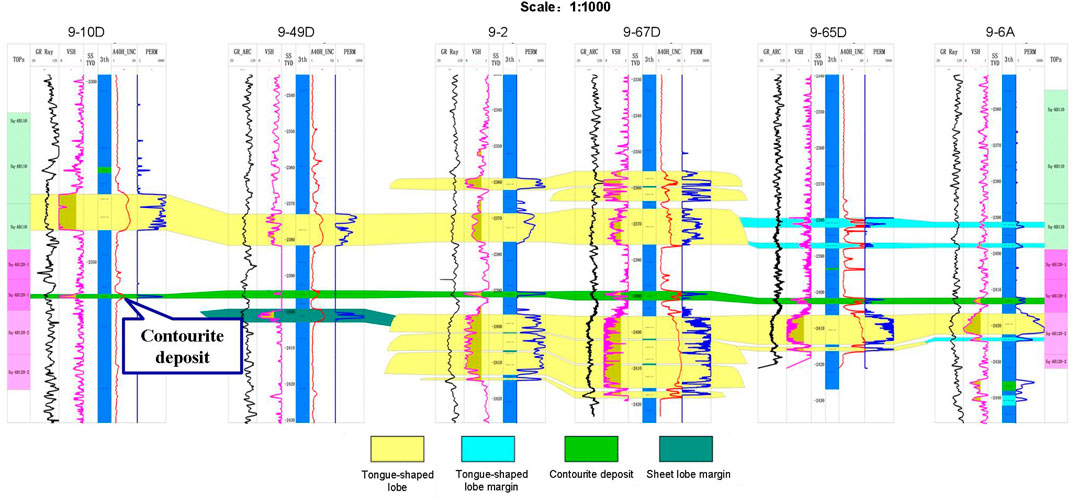
FIGURE 5. Contourite deposits at the top of the AB120 reservoir.
Following the determination of the sedimentary microfacies types, a sectional facies analysis of the AB120 Reservoir was done using integrated well-log and seismic data.
Marked retrogression is evident along the source direction, which is associated with a rise in the relative sea level and a decrease in supply from the source. Analysis of the well-log-calibrated seismic data revealed that high-amplitude continuous reflections characterized the AB110 and AB120 Reservoirs. On the side close to the source, onlap points are recognizable during seismic events. In addition, the vertical thickness of the sand bodies gradually decreased from the bottom of the units to the top. These findings suggest a rapid rise in relative sea level and a rapid decrease in supply from the source during the corresponding period (Figure 6).
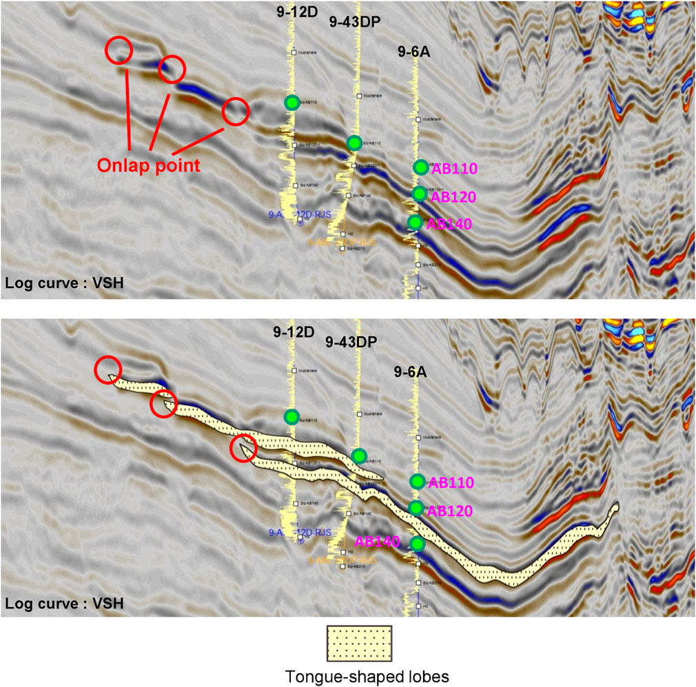
FIGURE 6. Well seismic profile along the source direction of AB110—AB120 reservoir.
In the direction perpendicular to the source direction, moving from the proximal end of the tongue-shaped lobes to their distal end, the sand bodies in the AB110 and AB120 Reservoirs varied in their origin and scale. Within the AB110 and AB120 Formation, at the proximal end of the tongue-shaped lobes, two moderate-to high-amplitude continuous reflection events are visible on the seismic section corresponding to their oil-bearing sand bodies. In addition, the seismic section shows marked erosional truncation points and a U-shaped reflection structure filled with low-amplitude seismic facies, which indicate muddy channel deposits (Figure 7). At the distal end of the tongue-shaped lobes, there remains only one moderate-to high-amplitude continuous reflection event within the target layer, which, as revealed by the well-log-calibrated seismic data, corresponds to the AB120 oil-bearing sand body. This suggests the disappearance of the AB110 oil-bearing sand body at this location due to a rapid rise in sea level and the decrease in supply from the source. Moreover, the U-shaped reflection structure in the AB120 Formation on the seismic section was inconspicuous, indicating a weakened downcutting capacity of the channels on the distal side from the source.
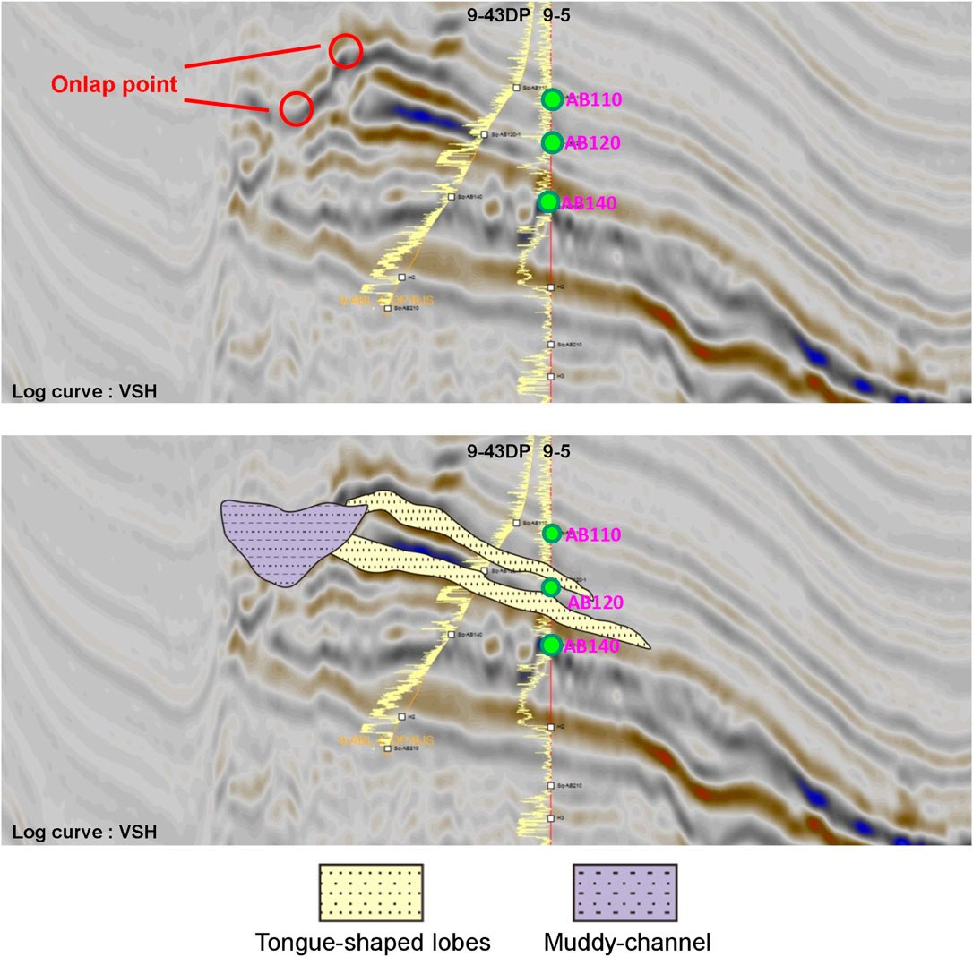
FIGURE 7. Well seismic profile in the direction perpendicular to material source supply from AB110 to AB120 reservoir — near source end.
Based on the stratigraphic framework and seismic horizon interpretations, the planar seismic attributes (e.g., RMS amplitude, maximum amplitude, minimum amplitude, coherent attribute, minimum impedance, maximum impedance, and average impedance) of the AB120 Reservoir were extracted. These attributes and their correlations with parameters such as sandstone and mudstone thicknesses and the sandstone–formation thickness ratio were analyzed. The RMS and wave impedance attributes were identified as the most sensitive and were selected for further analysis. The limit values corresponding to the sandstone facies were subsequently determined. The lower-limit RMS amplitude and upper-limit minimum impedance of the sandstone facies in the AB120 Reservoir are 20 and 5,850, respectively (Figures 8, 9).
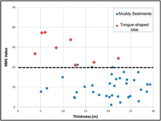
FIGURE 8. Relationship between thickness and RMS amplitude of different microfacies in AB120 reservoir.
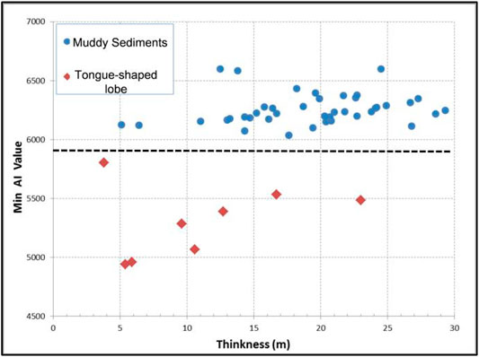
FIGURE 9. Relationship between thickness and minimum impedance of different microfacies in AB120 reservoir.
The minimum impedance was selected to interpret the sandstone facies based on the determined limit values of its seismic attributes. Through the minimum impedance analysis of single-well facies in a superimposed AB120 Formation, the sandstone facies was identified as the dominant facies in the low value area. The dominant facies in the high value area was the mudstone facies, and the sandstone-mudstone transition facies was in the central numerical area. A sedimentary microfacies distribution model for the AB120 Reservoir was produced through an integration of the single-well facies analysis, cross-well sectional facies analysis, and sensitive attributes. Tongue-shaped lobes were present in the main body of the AB120 Reservoir, and their roots were connected to muddy and sandy channels (Figure 10).
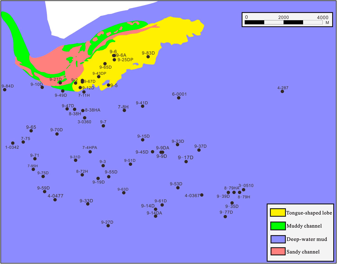
FIGURE 10. Sedimentary microfacies distribution model for the AB120 Formation based on the integrated well-log and seismic data.
The architecture of a reservoir refers to the morphology, scale, and direction of its constituent elements at varying levels, including how they are stacked (Allen, 1977; Allen, 1978). This concept reflects the spatial arrangement of the reservoir storage elements of varying origins and levels and seepage barriers, as well as the difference between the distribution patterns of these elements. Characterizing reservoir architectures is vital for the evaluation and development of oil and gas reservoirs.
The hierarchical structure of a sedimentary body is the result of multiple levels and rates of sedimentary environments. Generally, a sedimentary body is hierarchically divided based on its architectural bounding surfaces (ABSs), which are hierarchically sequential contact surfaces between the rock layers. A stratum can be split into genetically linked stratigraphic blocks based on its ABSs (Miall, 1985).
Based on prior understanding of ABS systems, the deep-water sedimentary ABSs in the Albacora Leste (ABL) oilfield are categorized into seven levels (1–7), with levels 1 and 7 being the lowest and highest levels, respectively, using deep-water sedimentary architectures and characteristics of the ABL oilfield as reflected by its geological, well-log, and seismic data.
Level 7 is a complex fan, which corresponds to layers AB250-110 and contains a complete stratigraphic formation. This level can be traced throughout the basin. Level 6 consists of single fans and includes sequence stratigraphic elements in the target layer (i.e., AB120). Level 5 is composed of channelized-lobe systems, including deposits in multiple sedimentary environments and flow types. Level 4 comprises complex lobes or complex lobe systems that are deposits formed by the same sedimentation mechanism but at different stages. The particle size, thickness, and spatial trends of the sedimentary rock displayed patterns. Level 3 consists of single lobes that are deposits formed by the same sedimentation mechanism and stage. They were similar in terms of particle size, thickness, and spatial trends. Level 2 is composed of rock facies sequences with single sedimentary elements. Level 1 comprises single rock facies that are further breakdowns of individual sedimentary elements, such as single sections in the Bouma sequence that are similar in particle sizes and sedimentary structures.
First, to characterize a specific reservoir requires the selection of appropriate levels. If the levels are too low, the results cannot meet the development and production needs, whereas if the levels are too high, the results are inadequate to allow for good predictions. The determination of the levels suitable for characterization depends on the data abundance and quality. The following section outlines the selection of suitable levels for the architectural characterization of the ABL oilfield through site-specific data.
Levels 3 and 2 ABSs had distinctly identifiable features in the core data of the study area. Further meticulous observation and description of the core data revealed Level 1 ABSs with extremely high vertical resolution. However, because of operating expenditure constraints, there are only a limited number of coring wells in the study area, which presents a tremendous challenge to transverse tracing of ABSs and comparing low-level ABSs based on cores retrieved from different wells is a daunting task.
Observation of the well-logs obtained for the study area revealed notable well-log responses for Level 3 ABSs likely due to the abundance of calcareous layers present at these locations. Therefore, Level 3 ABSs can be identified from the well-log data in the vertical direction. However, the large distances between the deep-water drilling wells in the study area present an obstacle to the transverse tracing of Level 3 ABSs. In contrast, the lobe deposits exhibit good transverse continuity. Therefore, transversely tracing lobe deposits is more likely to succeed than in tracing channel deposits. However, channelization in the study area results in ambiguity for the transverse tracing of the Level 3 ABSs between single lobes based on the well-log data.
The available seismic data cover the entire study area. An analysis of the well-log-calibrated seismic data for the target layer in the ABL oilfield identifies Level 4 ABSs (i.e., intercomplex ABSs) and, in some areas, Level 3 ABSs (i.e., ABSs between single-origin elements).
Based on the above comprehensive abundance and quality analysis of the data for the study area, Level 4 architectural elements were selected to facilitate architectural characterization of the target layer in the ABL oilfield.
The identification of architectural element boundaries is a key step in architectural characterization. The following four characteristics were used in this study as markers for identifying the boundaries of architectural elements:
Sedimentary microfacies analyses revealed the presence of two primary sedimentary microfacies in the study area: complex channels and lobes. These products were formed in different sedimentary environments and constitute architectural elements of different types and levels. There is often a seepage barrier or change at the boundaries of these microfacies, resulting in disconnection or poor connection between the sand bodies. Therefore, each boundary displaying a change in lateral facies is an architecture boundary (Figure 11).
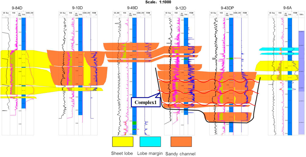
FIGURE 11. Architecture boundary characteristics with lateral phase change in ABL oil field.
Elements which formed at different stages and have different origins differ in terms of their period of development. Therefore, corresponding sand bodies have different relative elevation of their top horizons and the marker bed which is the formation boundary. In practice, the measured elevation difference must be combined with the curve patterns, scale and extension of the sand bodies to determine the boundaries of the architectural elements accurately (Figure 12).
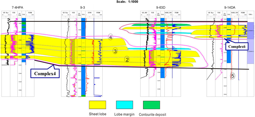
FIGURE 12. Architecture boundary characteristics of sand bodies with elevation difference in ABL oil field.
Changes in the shale content, extent of erosion, and cross-cutting and stacking relationships at the boundaries of the sedimentary bodies of different stages lead to marked changes in the seismic response characteristics. This is primarily reflected by phenomena such as the appearance of erosional truncation points and changes in the amplitude (Figure 13).
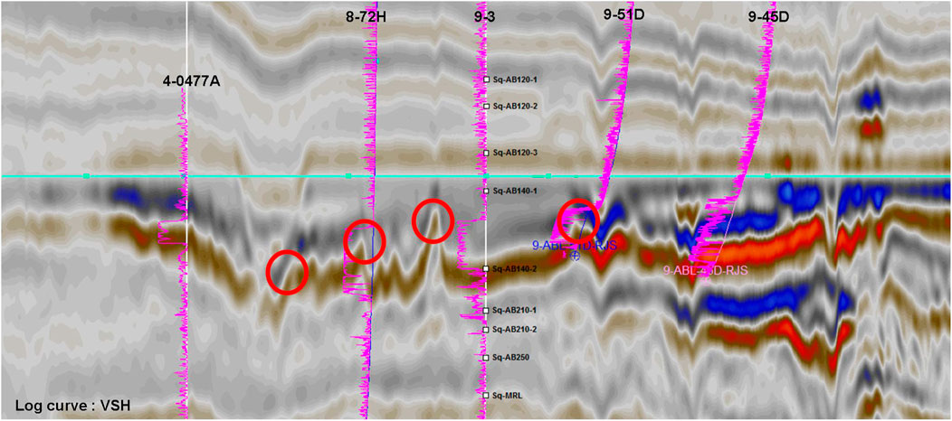
FIGURE 13. Seismic amplitude change of architecture boundary characteristics for sand body in ABL oil field.
A lobe is characterized by a flat bottom and a convex top. The sand body deposits are thicker along the central flow line of a single lobe and gradually thin out towards its edges. Therefore, the sand body thickness may first decrease and then increase, moving from one single lobe to another. At the macroscopic level, the boundaries of the architectural elements can be approximated based on the thickness contours of the sedimentary body.
An earlier sedimentary microfacies analysis revealed that the AB120 Reservoir formed in a deep-water submarine-fan sedimentary environment and contained tongue-shaped, sandy channel, muddy channel, and contourite deposits. Contourite deposits are difficult to distinguish on the seismic sections owing to their small thickness (approximately 2 m) which inhibits their detailed characterization in this study. The following section presents an architectural characterization and analysis of the AB120 Reservoir based on complex lobe and channel elements.
A previous analysis of the deep-water submarine-fan sedimentary facies in the study area revealed that tongue-shaped lobes primarily consist of massive fine sandstone sediments. Well-log observations revealed a low GR value, low density, large arrival-time difference, and high electrical resistance in the reservoir layer, suggesting good reservoir quality (Figure 14A). It has been reported that a complex-lobe sedimentary body was found in the study area during the drilling of 12 wells, most of which were clustered in the western tongue-shaped lobe.
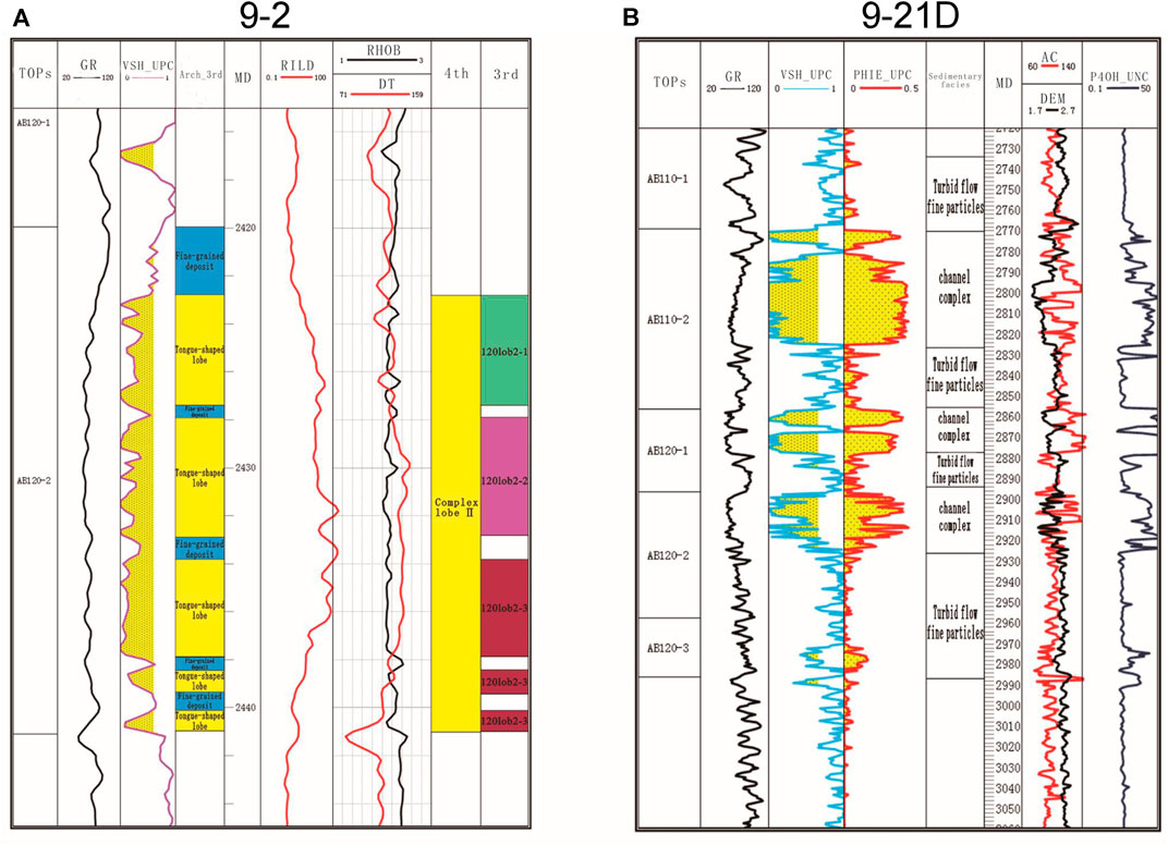
FIGURE 14. Architectural characterization of single well. [(A) Architectural characterization of the complex lobes in Well 9–2; (B) Architectural characterization of the complex channels in Well 9–21D).
Because of factors such as shale content and basal lag deposits, single lobes formed at different stages may differ in terms of their vertical well-log patterns, and their contact interfaces may be associated with high GR values. On this basis, single-well data can be used to distinguish between single lobes. Three single lobes of different stages were present in the AB120 Reservoir (Figure 14A).
Integrated well-log and seismic data revealed the presence of two complex lobes formed at different stages in the AB120 Reservoir based on sectional architectural analysis. The complex lobes in the eastern undrilled area and western drilled area are denoted by I and II, respectively. Marked well-logs and seismic responses can also be observed for complex lobe II.
Along the source direction, the AB120 Formation was characterized by continuous high-amplitude reflections, which suggest an overall dominance of tongue-shaped lobe deposits. There is a significant decrease in the amplitude of seismic reflections at the lowest part of the architecture. This location represented the boundary between the complex lobes. In the section perpendicular to the source direction shown in Figure 15, the geological body is characterized by a continuous, high-amplitude reflection structure. Well-log-calibrated seismic data revealed that these structures were tongue-shaped deposits.
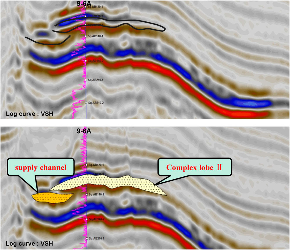
FIGURE 15. Well-log and seismic responses of the AB120 reservoir in the direction perpendicular to the source direction.
Each complex lobe also has a complex internal structure which is difficult to characterize in undrilled areas. This study focused on investigating the complex lobe in the drilled area (i.e., complex lobe II) based on Level 3 architectural elements (e.g., single lobes). Based on single-well architectural characterization, single lobes were identified. A cross-well comparison revealed the presence of three single lobes in complex lobe II which formed at different development stages of the AB120 Reservoir in the vertical direction. The youngest lobe was distributed over the largest area (Figure 16). The three single lobes are difficult to identify and characterize using seismic profiles owing to the thinness (2–20 m) of complex lobe II and the low vertical resolution of the seismic data.
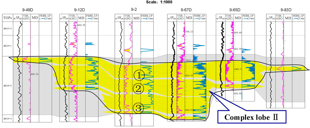
FIGURE 16. Cross-well section of the AB120 reservoir.
In the plane, there were two regions in the study area with a low minimum impedance. One is located along the line connecting Wells 9–2, 9–65D, and 9-6A in the work area, whereas the other is situated in the northern part of the study area where no drilling has been conducted to date. Differences in shale content, as well as sandstone and mudstone conditions, can lead to changes in seismic attributes near the boundaries or junctions of different sedimentary bodies. In the study area, impedance may first increase and then decrease at the boundaries or junctions of different sedimentary bodies. This distribution pattern was observed in the minimum impedance of the AB120 Reservoir, which supports the earlier finding that two complex lobes exist in this reservoir (Figure 17).
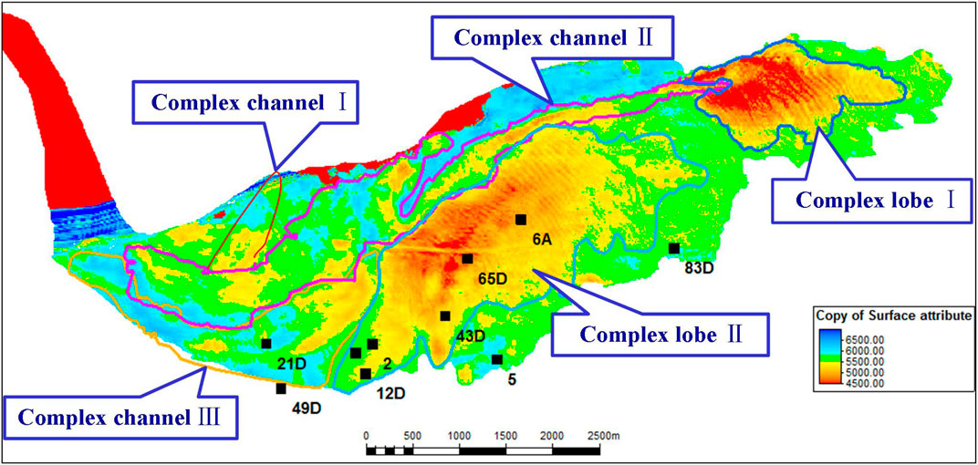
FIGURE 17. AB120 reservoir plane attribute map (minimum impedance distribution).
The boundaries of the architectural elements were characterized based on well-log and seismic data and guided by the sedimentation model obtained from the microfacies analysis. Interactive single-well, sectional, and planar characterizations were performed using integrated well-log and seismic data. A detailed 2D depiction (or “planar division”) of architectural elements was subsequently completed through the connection of their boundaries based on their geometrical relationships. An analysis of the reservoir architecture based on integrated well-log and seismic data revealed the presence of two complex lobes formed at different stages (I and II) in the AB120 Reservoir (Figure 17).
Deep-water submarine-fan channels can be categorized as follows based on paleo-geomorphological features: restricted, semi-restricted, and unrestricted channels (Clark and Pickering, 1996; Deptuck et al., 2003). Characterized by marked U- and V-shaped reflections on the seismic sections, restricted channels have notable downcut surfaces, and their boundaries show large, incised river valleys. In comparison, while semi-restricted channel systems have distinct downcutting surfaces, large-scale natural levee deposits are present at their edges and appear as seagull-shaped features in the seismic sections. The principal characteristic of unrestricted channels is the lack of notable incised river valleys at their boundary. In the study area, complex channel deposits were only encountered in the AB120 Formation during drilling of Well 9–21D. An analysis revealed that this channel is a restricted, enveloped, and complex channel, which is characterized by distinct U- and V-shaped reflections on seismic sections and has distinct downcutting surfaces. At present no vertical contact has occurred between sand bodies in complex channels. A stable interlayer composed of fine-grained sediments separated the sand bodies and corresponded to notable returns on the well-log (Figure 14B).
Within the AB120 Formation a seismic section perpendicular to the source direction and through Well 9–21D revealed distinctly discontinuous seismic events and multiple U-shaped reflection structures filled with high-amplitude seismic facies. These characteristics correspond to three sandy complex channels (denoted as I, II, and III). The stacking of these three complex channels on the seismic section suggests that complex channels I and III are the first and last to be deposited, respectively. The well-log-calibrated seismic data revealed that complex channel III was encountered during the drilling of well 9–21D (Figure 18).
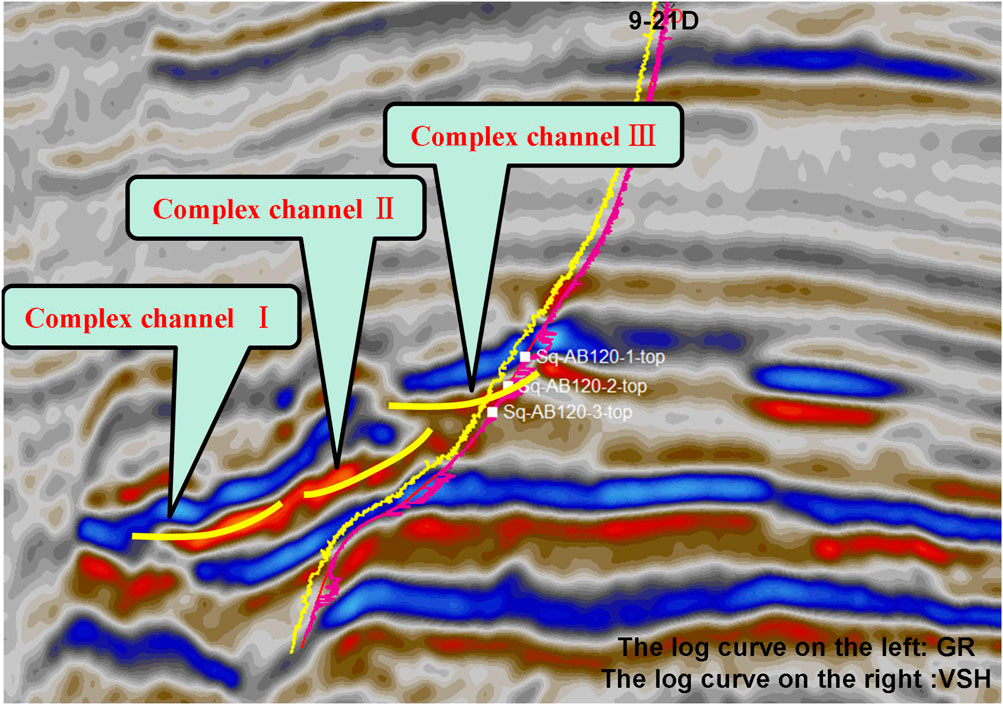
FIGURE 18. Seismic section of the AB120 reservoir perpendicular to the source direction and through well 9–21D.
Observation of a seismic section along the source direction and through Wells 9–21D and 9-2 showed that the AB120 Formation is characterized by marked continuous, high-amplitude reflections. In addition, onlap points were visible at the seismic events on the side close to the source. The well-log-calibrated seismic data indicated the formation of a channel (i.e., complex channel III) near the source (Figure 19).

FIGURE 19. Seismic section of the AB120 reservoir along the source direction and through wells 9–21D and 9-2
Notable discontinuous seismic events are visible within the AB120 Formation on the side furthest from the source and in the direction perpendicular to the source direction. In addition, there was a U-shaped reflection structure filled with high-amplitude seismic facies, which was inferred to be a complex channel (i.e., complex channel II) (Figure 20).
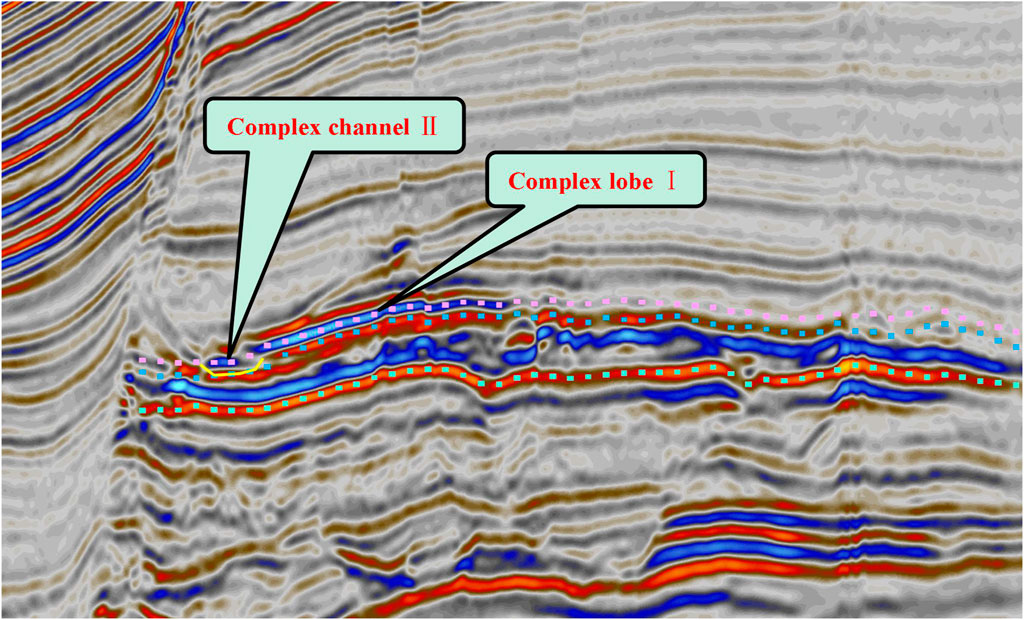
FIGURE 20. Seismic section of the AB120 reservoir perpendicular to the source direction (remote source end).
Changes in the shale content, extent of erosion, and cutting and stacking relationships at the boundaries of sedimentary bodies formed at different stages of reservoir development can cause considerable changes in the seismic response characteristics at the boundaries of architectural elements (e.g., changes in the seismic amplitude). The analysis of the extracted minimum impedance of the AB120 Reservoir agrees with previous findings that three complex channels (I, II, and III) may exist in the AB120 Reservoir (Figure 17). As the oldest of the three complex channels, complex channel I has been severely cut by younger complex channels and is distributed over a limited area in the northwestern part of the study area. The low quality of relevant seismic data due to the presence of large faults presents a challenge for obtaining a detailed description of complex channel I.
Based on the spatial relationship of the reflection structure in the seismic profile and the distribution characteristics of the wave impedance plane figure, it is considered that complex channels III and II are the supply channels for complex lobes II and I, respectively. The stacking of complex lobe II onto the supply channel for complex lobe I on the seismic sections, suggests that complex lobe I was deposited earlier than complex lobe II (Figures 15, 17, 19, 20).
(1) The AB120 Reservoir contains four primary sedimentary microfacies: tongue-shaped, muddy channel, sand channel, and contourite deposits. Thinly interbedded sandstone and mudstone form the bottom of each tongue-shaped lobe and transition upwards into massive fine sandstone. Tongue-shaped lobes are characterized by a typical funnel-shaped pattern on natural GR logs and high-amplitude, continuous reflections on the seismic sections. Vertically, the muddy channels are characterized in the seismic sections by a low-amplitude, imbricate reflection structure. The sandy channels are primarily composed of massive fine sandstone, display a positive rhythm and are characterized by a typical bell-shaped pattern on the natural GR logs and U- or V-shaped short-axis wavy reflections filled with moderate-to high-amplitude seismic facies in the seismic sections. Consisting of thinly interbedded sandstone (mainly silty fine sandstone) and mudstone, the contourite deposits have a thickness of approximately 2 m and are transversely distributed in a stable manner.
(2) A seven-level classification scheme was adopted for the deep-water submarine-fan ABS system in the study area. Because of data abundance and quality constraints, the configuration characterization of the study area can only identify up to Level 4 ABSs. Changes in the lateral facies, seismic amplitude, sand body thickness, and sand body elevation differences typically delineate the boundaries of architectural elements.
(3) The AB120 Reservoir consists of three complex channels (I, II, and III) and two tongue-shaped complex lobes (I and II). Complex channels I and III are the first and last to be deposited, respectively. Complex lobe I was deposited before complex lobe II. Complex channels II and III supply complex lobes I and II, respectively. Vertically, complex lobe II (located to the west) is composed of three single lobes formed at different stages, the youngest of which is distributed over the largest area.
The original contributions presented in the study are included in the article/Supplementary Material, further inquiries can be directed to the corresponding author.
CZ, XH, JL, and CY contributed to the conception and design of the study. JL wrote the first draft of this manuscript. ZN conducted the investigation and data collation. All authors contributed to manuscript revision, and have read and approved the final submitted version.
This study was financially supported by the National Natural Science Foundation of China (grant no. 42172175).
The authors declare that the research was conducted in the absence of any commercial or financial relationships that could be construed as a potential conflict of interest.
All claims expressed in this article are solely those of the authors and do not necessarily represent those of their affiliated organizations, or those of the publisher, the editors and the reviewers. Any product that may be evaluated in this article, or claim that may be made by its manufacturer, is not guaranteed or endorsed by the publisher.
We would like to thank the SINOPEC Shanghai Offshore Petroleum Branch for providing the data and allowing the publication of this article.
Allen, J. R. L. (1978). Studies in Fluviatile Sedimentation: an Exploratory Quantitative Model for the Architecture of Avulsion-Controlled Alluvial Suites. Sediment. Geology. 21, 129–147. doi:10.1016/0037-0738(78)90002-7
Allen, J. R. L. (1977). The Plan Shape of Current Ripples in Relation to Flow Conditions. Sedimentology 24 (1), 53–62. doi:10.1111/j.1365-3091.1977.tb00119.x
Bhuiyan, A. H., and Hossain, S. (2020). Petrographic Characterization and Diagenetic Evaluation of Reservoir Sandstones from Smørbukk and Heidrun fields, Offshore Norway. J. Nat. Gas Geosci. 5 (1), 11–20. doi:10.1016/j.jnggs.2019.12.001
Bybee, K. (2006). Albacora Leste Field - Subsea Production- System Development. J. Journal Pet. Technol. 58 (08), 59–60. doi:10.2118/0806-0059-JPT
Clark, J. D., and Pickering, K. T. (1996). Submarine Channels:Processes and Architecture. London: Vallis Press.
Deptuck, M. E., Steffens, G. S., and Barton, M. (2003). Architecture and Evolution of Upper Fan Channel-Belts on the Niger Delta Slope and in the Arabian Sea. Mar. Pet. Geology. 20 (6- 8), 649–676. doi:10.1016/j.marpetgeo.2003.01.004
Fetter, M., De Ros, L. F., Bruhn, C. H. L., Carlos, H., and Bruhn, L. (2009). Petrographic and Seismic Evidence for the Depositional Setting of Giant Turbidite Reservoirs and the Paleogeographic Evolution of Campos Basin, Offshore Brazil. Mar. Pet. Geology. 26 (6), 824–853. doi:10.1016/j.marpetgeo.2008.07.008
Gao, S., Liu, H., Ye, L., Wen, Z., Zhu, W., and Zhang, C. (2020). A New Method for Well Pattern Density Optimization and Recovery Efficiency Evaluation of Tight sandstone Gas Reservoirs. Nat. Gas Industry B 7 (2), 133–140. doi:10.1016/j.ngib.2019.08.003
Gervais, A., Mulder, T., Gonthier, E., and Savoye, B. (2006). Sandy Modern Turbidite Lobes:A New Insight from High Resolution Seismic Data. J. Mar. Pet. Geology. 23 (4). doi:10.1016/j.marpetgeo.2005.10.006
Gu, C., Li, Q., Ma, R., Lin, Y., Li, X., Li, Y., et al. (2021). Propagation Characteristics of Doppler Ultrasonic Wave in Gas-Liquid Two-phase Flow in an Offshore deepwater Riser. Nat. Gas Industry B 8 (6), 615–621. doi:10.1016/j.ngib.2021.11.009
Kang, H., Meng, J., Cheng, T., Jia, H., Bai, B., and Li, M. (2018). Characteristics of Deep Water Depositional System in Campos basin, Brazil. J. Petroleum Exploration Develop. 45 (01), 93–104. doi:10.11698/PED.2018.01.0910.1016/s1876-3804(18)30009-0
Li, C., Chen, G., Zhang, G., Lv, C., Yang, H., Ma, M., et al. (2017). Developmental Characteristics and Provenances of the Submarine Fans Developed During the Middle Miocene in the Eastern Deepwater Area of the Qiongdongnan Basin. J. Natural Gas Geoscience 28 (10), 1555–1564. doi:10.11764/j.issn.1672-1926.2017.08.009
Li, P., Zhou, S., Ji, B., Liu, X., Li, J., Zhang, X., et al. (2021). Water-soluble Organic Acids in Sedimentary Rocks: Compositions and Influencing Factors. J. Nat. Gas Geosci. 6 (3), 173–181. doi:10.1016/J.JNGGS.2021.06.003
Liang, J., Huang, X., Cai, W., Wang, Y., Chen, L., Zhang, Y., et al. (2019). Source-to-Sink System and Exploration Prospects of the Wilcox Formation in Perdido Fold Belt, Burgos Basin. Mexico. J. Acta Petrolei Sinica. 40 (12), 1439–1450. doi:10.7623/syxb201912003
Lima, B. E. M., and De Ros, L. F. (2019). Deposition, Diagenetic and Hydrothermal Processes in the Aptian Pre-salt Lacustrine Carbonate Reservoirs of the Northern Campos Basin, Offshore Brazil. Sediment. Geology. 383, 55–81. doi:10.1016/j.sedgeo.2019.01.006
Lin, Y., Wu, S., Wang, X., Ling, Y., Lu, Y., Zhang, J., et al. (2014). Composite Sand Bodies Architecture of Deep-Water Turbidite Channels in the Niger Delta Basin. J. Acta Geologicasinica(englishedition). 88 (06), 1822–1834. doi:10.1111/1755-6724.12348
Liu, L., Zhang, T., Zhao, X., Wu, S., Hu, J., Wang, X., et al. (2013). Sedimentary Architecture Models of deepwater Turbidite Channel Systems in the Niger Delta continental Slope, West Africa. Pet. Sci. 10 (02), 139–148. doi:10.1007/s12182-013-0261-x
Liu, Y., Wang, H., Meng, W., Zhang, C., Zhi, J., and Shen, A. (2020). Stimulation experiment of Horizontal wells Filled with Permeable and Water-Blocking Gravel in Deepsea Bottom-Water Gas Reservoirs. Nat. Gas Industry B 7 (4), 390–396. doi:10.1016/j.ngib.2020.01.006
Ma, Z., Xie, Y., Geng, C., and Zhang, F. (2011). Petroleum Geology and Favorable Exploration Targets of Campos Basin,Brazil. J.Journal Jilin University:Earth Sci. Edition 41 (05), 1389–1396. doi:10.13278/j.cnki.jjuese.2011.05.021
Mann, P., Horn, M., and CrossⅠ, (2007). Tectonic Setting of 79 Giant Oil and Gas Fields Discovered from 2000-2007:Implications for Future Discovery Trends. Long Beach, California: AAPG,Annual Convention.
Miall, A. D. (1985). Architectural-element Analysis: A New Method of Facies Analysis Applied to Fluvial Deposits. Earth-Science Rev. 22, 261–308. doi:10.1016/0012-8252(85)90001-7
Obafemi, S., Oyedele, K. F., Omeru, T., and Bankole, S. I. (2020). Characterization of Deep Water Turbidite Channels and Submarine Fan Lobes Using Artificial Intelligence; Case Study of Frem Field Deep Offshore Niger Delta. J. Afr. Earth Sci. 167, 103852. doi:10.1016/j.jafrearsci.2020.103852
Pandolpho, B. T., da Fontoura Klein, A. H., Dutra, I., Mahiques, M. M., Viana, A. R., Bueno, G. V., et al. (2021). Seismic Record of a Cyclic Turbidite-Contourite System in the Northern Campos Basin, SE Brazil. Mar. Geology. 434, 106422. doi:10.1016/J.MARGEO.2021.106422
Pu, R., Du, J., Cui, Y., and Shen, J. (2003). Some Examples of Lacustrine Retrogradation Reflection. J. Oil Geophysical Prospecting. 67–71+117-118+112. doi:10.13810/j.cnki.issn.1000-7210.2003.01.016
Reimchen, A. P., Hubbard, S. M., Stright, L., and Romans, B. W. (2016). Using Sea-Floor Morphometrics to Constrain Stratigraphic Models of Sinuous Submarine Channel Systems. Mar. Pet. Geology. 77, 92–115. doi:10.1016/j.marpetgeo.2016.06.003
Romans, B. W., Fildani, A., Hubbard, S. M., Covault, J. A., Fosdick, J. C., and Graham, S. A. (2011). Evolution of Deep-Water Stratigraphic Architecture, Magallanes Basin, Chile. Mar. Pet. Geology. 28 (3), 612–628. doi:10.1016/j.marpetgeo.2010.05.002
Sajid, Z., Ismail, M. S., Tsegab, H., Hanif, T., and Ahmed, N. (2020). Sedimentary Geology and Geochemical Approach to Determine Depositional Environment of the Triassic Turbidites Bearing Semanggol Formation, NW Peninsular Malaysia. J. Nat. Gas Geosci. 5 (4), 207–226. doi:10.1016/j.jnggs.2020.07.001
Sun, G., Wang, Y., Jiang, Y., Pan, S., Zhang, S., and Zhang, M. (2020). Provenance and Tectonic Setting of Paleogene sandstone in the center of the Northern Qaidam Basin, China. J. Nat. Gas Geosci. 5 (5), 273–284. doi:10.1016/j.jnggs.2020.09.002
Tang, H., Tang, H., He, J., Zhao, F., Zhang, L., Liao, J., et al. (2021). Damage Mechanism of Water-Based Fracturing Fluid to Tight sandstone Gas Reservoirs: Improvement of the Evaluation Measurement for Properties of Water-Based Fracturing Fluid: SY/T 5107-2016. Nat. Gas Industry B 8 (2), 2021163–2021172. doi:10.1016/j.ngib.2020.09.016
Walker, R. G. (1978). Deep—water sandstone Facies and Ancient Submarine Fans: Models for Exploration for Stratigraphic Traps. J. AAPG Bull. 62 (6), 932–966. doi:10.1306/c1ea4f77-16c9-11d7-8645000102c1865d
Wang, L., Pan, J., and Yang, L. (2020). Present Conditions and Prospect of Global Deepwater Oil and Gas Exploration and Development. J. Oil Forum. 39 (02), 31–37. doi:10.3969/j.issn.1002-302x.2020.02.005
Wang, W., Zhu, Y., Yu, C., Zhao, L., and Chen, D. (2020). Pore Size Distribution in the Tight sandstone Reservoir of the Ordos Basin, China and Their Differential Origin. J. Nat. Gas Geosci. 5 (2), 45–55. doi:10.1016/j.jnggs.2020.02.001
Weimer, P., and Link, M. H. (1991). Global Petroleum Occurrences in Submarine Fans and Turbidite Systems.Seismic Facies and Sedimentary Processes of Submarine Fans and Turbidite Systems. New York: Springer, 9–67. doi:10.1007/978-1-4684-8276-8_2
Yin, S. (2018). The Global Distribution of Oil and Gas Resourses in Deep Waters. Beijing, China: China university of petroleum. doi:10.27643/d.cnki.gsybu.2018.001084
Zhang, J., and Wu, S. (2019). Research Progress on the Depositional Architecture of Submarine-Fan Lobes. J.China Offshore Oil and Gas 31 (5), 88–106. doi:10.11935/j.issn.1673-1506.2019.05.010
Zhang, J., Wu, S., Wang, X., Lin, Y., Fan, H., Jiang, L., et al. (2015). Reservoir Quality Variations within a Sinuous Deep Water Channel System in the Niger Delta Basin, Offshore West Africa. J.Marine Pet. Geology. 63. doi:10.1016/j.marpetgeo.2015.02.041
Zhao, X., Wu, S., and Liu, L. (2012). Characterization of Reservoir Architectures for Neogene deepwater Turbidity Channels of Akpo Oilfield,Niger Delta Basin. J. Acta Petrolei Sinica. 33 (06), 1049–1058.
Keywords: deep-water sedimentation, tongue-shaped lobes, Albacora Leste oilfield, sedimentary microfacies, architectural characterization
Citation: Zhao C, Hu X, Li J, Yi C, Li J and Niu Z (2022) Characterization of Deep-Water Submarine Fan Reservoir Architecture: AB120 Reservoir in the Campos Basin. Front. Earth Sci. 10:892902. doi: 10.3389/feart.2022.892902
Received: 09 March 2022; Accepted: 11 April 2022;
Published: 27 April 2022.
Edited by:
Dongming Zhi, PetroChina, ChinaReviewed by:
Yong Dan, Chinese Academy of Geological Sciences, ChinaCopyright © 2022 Zhao, Hu, Li, Yi, Li and Niu. This is an open-access article distributed under the terms of the Creative Commons Attribution License (CC BY). The use, distribution or reproduction in other forums is permitted, provided the original author(s) and the copyright owner(s) are credited and that the original publication in this journal is cited, in accordance with accepted academic practice. No use, distribution or reproduction is permitted which does not comply with these terms.
*Correspondence: Xiuquan Hu, aHV4aXVxdWFuMTVAY2R1dC5lZHUuY24=
Disclaimer: All claims expressed in this article are solely those of the authors and do not necessarily represent those of their affiliated organizations, or those of the publisher, the editors and the reviewers. Any product that may be evaluated in this article or claim that may be made by its manufacturer is not guaranteed or endorsed by the publisher.
Research integrity at Frontiers
Learn more about the work of our research integrity team to safeguard the quality of each article we publish.