- Key Laboratory of Earthquake Engineering and Engineering Vibration, Institute of Engineering Mechanics, China Earthquake Administration, Key Laboratory of Earthquake Disaster Mitigation, Ministry of Emergency Management, Harbin, China
In this article, a centrifuge shaking table model test of anchored stabilizing piles for strengthening landslides was established, and the dynamic response characteristics of the pile–anchor–slope under earthquake action were analyzed. On this basis, combined with the fuzzy gray relational analysis and the rank-sum ratio method, the correlation between the amplification of the acceleration response of the heterogenous slope and the dynamic response of the support structure was explored. Based on the obtained results, relevant suggestions for engineering design were proposed. The results showed that the seismic amplification of the complex soil–rock slope reinforced by the pile–anchor structure was not uniform and the amplification coefficient had strong variability. Among them, the amplification coefficient of the slope, dynamic earth pressure, and dynamic bending moment of the pile near the connection of the pile–anchor cable continued to increase; the correlation between the seismic amplification and the seismic behavior of the pile–anchor structure is different at different positions of the slope. The measurement points with a higher comprehensive ranking of correlation are mainly concentrated in the pile–anchor connection, the middle of the slope, and the high-angle soil–rock interface. It is related to the geometric characteristics of the model and the high seismic amplification of the slope; for the pile–anchor connection part and the high-angle soil–rock structure surface of the slope, the shock absorption measures and grouting strength of the anchor cable’s anchoring section should be considered in the engineering design.
1 Introduction
Strong earthquake action and complex geological conditions inevitably lead to a large number of earthquake landslides. Landslides induced by large earthquakes have a strong disaster-causing capacity. In the early 21st century alone, tens of thousands of people have been killed and billions of dollars have been lost (Huang and Li, 2009; Halder et al., 2021; and Hu H. Q et al., 2021). Therefore, utilizing reinforcement technologies to improve the stability of slopes in seismically active areas has become one of the popular research topics in the field of geological disaster prevention (Liu et al., 2021; Chen et al., 2022).
As a new reinforcement technology, anchored stabilizing piles can effectively improve slope stability and thus have been applied to treat large or super large landslides in many countries (Wang, 1998; Zhao, et al., 2017). The Wenchuan earthquake damage investigation found that the slope reinforced with pre-stressed anchored stabilizing piles was not damaged when the fortification intensity of the structure was exceeded and has good seismic resistance (Zhou et al., 2010). So far, the quasi-static method has been adopted in the seismic design of anchored stabilizing piles, which lacks a recognized and reasonable method system and ignores the influence of the seismic dynamic effect. Due to the complex stress system of the structure, the action mechanism of the anchor cable and the dynamic interaction of pile–anchor–soil mass are still unclear. The seismic response law of the anchored stabilizing pile is to reveal the seismic mechanism and failure mode of the anchored stabilizing pile, the dynamic interaction law of the pile–anchor–slope mass, and establish a scientific foundation for the seismic design method. Therefore, the research on the dynamic response of anchored stabilizing piles has an important theoretical value.
Field measurement and physical model tests are the most reliable methods to study the mechanical properties of anchored stabilizing piles. Recently, a series of 1-g large-scale shaking table tests have been conducted to analyze the mechanical characteristics of anchored stabilizing piles and slope deformation (Ma et al., 2019; Hu M. M et al., 2021). However, these tests can only qualitatively reveal the seismic response law of the anchor–pile structures because the 1-g shaking table test cannot simulate the actual stress–strain relationship in the field (Garala and Madabhushi, 2019). Especially in tests related to slope stability, the influence of the slope self-weight is significant. Meanwhile, the nonlinear change in the in situ modulus and the modulus with a strain in the soil has a strong impact on soil–structure interaction (Finn et al., 1986). This can also affect the deformation and displacement of the slope, thus making the dynamic behavior of retaining structures unreliable. In contrast, the centrifuge test can simulate real gravity through the centrifuge force formed by high-speed rotation. Therefore, this technology can effectively reflect the stress field of the prototype and has been widely applied to many fields (Zelikson et al., 1983; Ghosh and Madabhushi, 2007). Unfortunately, only a few studies have used this technology to analyze the seismic performance of anchored stabilizing piles. Zheng et al. (2016) conducted a centrifuge shaking table test to discuss the seismic response characteristics of a slope reinforced by anchored stabilizing piles and determined the distribution of soil pressure and the bending moment of the pile and its variation laws with different input ground motions. Huang et al. (2020) used a silica gel model instead of soil to examine the seismic stress characteristics and ultimate failure mode of the pile–anchor structures when the slope continued to slide along the circular arc sliding surface. In addition, the theoretical calculation model is also one of the reference methods to explore the pile–soil interaction. Ni et al. (2017) proposed the deflection model of the pile under transverse load and deduced the distribution mode of surrounding soil displacement and earth pressure.
The existing tests based on a 1-g shaking table or the centrifuge shaking table mainly focused on the seismic capacity of the retaining structure but ignored the influence of the slope response on the structures. Recent studies have demonstrated that the propagation of a ground motion in nonuniform slopes is very complex and can significantly affect the mechanical behavior of structures (Veletsos and Younan, 1997; Gazetas et al., 2004; Psarropoulos et al., 2005). This may cause the actual response of the project to not meet the expectations and has been confirmed in many earthquake investigations (Zhang et al., 2012; Liu et al., 2016). Therefore, it is necessary to study the correlation between the seismic response of the slope and the seismic behavior of the anchored stabilizing piles.
The methods of analyzing data relevance generally include mathematical statistics, machine learning, and gray relational analysis. However, there are some problems in mathematical statistics, such as regression analysis, analysis of variance, and principal component analysis. This method does not apply to the dynamic response model test results with a complex and no obvious probability distribution form. With the development of computers, machine learning has been gradually introduced into the field of geotechnical engineering and has played an important role in many directions (Ni et al., 2018; Ni and Mangalathu, 2018; Ni et al., 2020). However, due to limited data of the centrifugal shaking table test of anchored stabilizing piles, this method has not been applied. Fortunately, gray relational analysis solves this problem well. This method is also applicable to the number of samples and whether the samples are regular (Deng, 2002).
In this study, centrifuge shaking table tests of reinforcing an accumulation landslide with anchored stabilizing piles are conducted. Based on the test results, the correlation between the slope seismic response and pile mechanical parameters was discussed using fuzzy gray relational analysis (FGRA). In addition, combined with the rank-sum ratio (RSR) method, the influence classification of the amplification effect of different slope positions was further divided to give targeted suggestions for engineering design and reinforcement. The results may provide a reference for the optimal design of anchored stabilizing piles.
2 Centrifuge Shaking Table Test
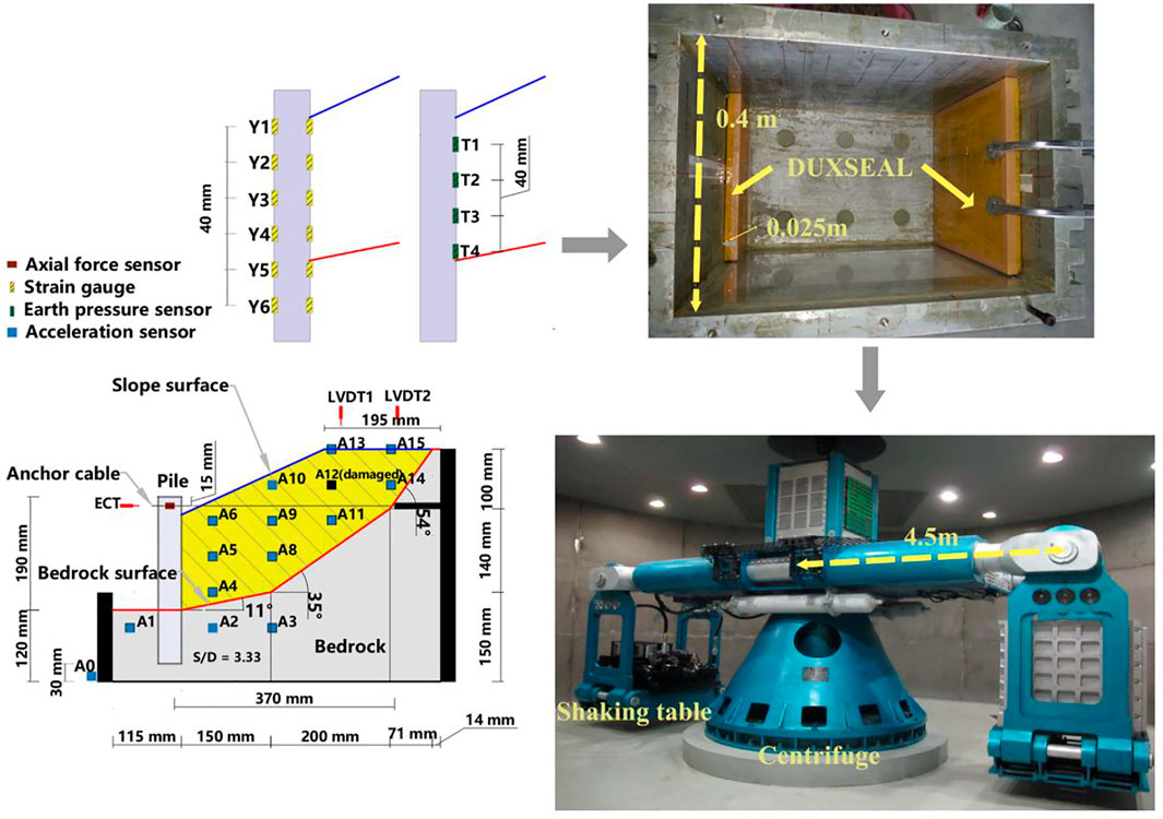
The test model adopted the large-scale geotechnical centrifuge physical simulation system of Zhejiang University, including the ZJU400 geotechnical centrifuge, electro-hydraulic servo shaking table, and rigid wall model box. The reliability of this test system has been verified many times (Sun et al., 2020; Yan et al., 2020). The relevant design parameters of the ZJU400 centrifuge and its shaking table are referred to in some previous studies (Zheng et al., 2016).
It is worth noting that because the model box belongs to finite boundary conditions during dynamic tests such as the seismic loading test, the input ground motion will be reflected when it propagates to the boundary of the model box, resulting in data distortion. Some scholars have developed a layered shear model box which effectively eliminates the reflection of the ground motion boundary under its small shear resistance, but this model box has little effect on the model with large stiffness. Therefore, after comprehensively considering the test model and test equipment in this study, we decided to adopt the fixed-wall rigid model box bearing model. In addition, to avoid the influence of possible boundary effects brought by the rigid model box on the test results, we used DUXSEAL to absorb the ground motion transmitted to the boundary. This method draws on previous related studies (Heron et al., 2015; Cilinger and Madabhushi, 2011). In this research, the absorbing material with a thickness of 25 mm was used. In addition, vaseline was applied on the left and right sides of the model box in the vertical loading direction to reduce the friction between the geotechnical model and the box.
Although the research purpose of this study is not to evaluate the seismic capacity of specific projects, the establishment of the test model has been referred to the anchored stabilizing pile reinforcement project found by Liu et al. (2016) so that the research results can be used as a reference in the design of other similar projects. The centrifuge acceleration of the test was set to 50 g, and the scaling laws are given in Table 1. The selection of the centrifugal similarity scale is referred to in previous related studies (Yan et al., 2020). The geometric dimensions and sensor positions of the test model are shown in Figure 1. A variety of sensors were used to obtain the test records of different parameters, including earth pressure sensors (0–1 MPa, 1 %FS), bending moment strain gages (2000 microstrain, 0.1%), axial force sensors (Zheng et al., 2016), micro acceleration sensors (0–50 g, ≤5%), and displacement sensors (±20 mm, 0.03%FS). All types of sensors were calibrated before the test and connected with the automatic acquisition equipment of the centrifuge during the test.
The sliding mass and bedrock were simulated by the remolded prototype slope Xigeda soil and cement soil (silty clay: cement: quartz sand: water = 1: 0.55: 1: 0.25). To obtain the total shear strength parameters (cohesion c and internal friction angle φ) of the simulated material, the failure strength of specimens under different confining pressures was obtained by the unconsolidated undrained triaxial test; then, the Mohr circle and shear strength envelop of the sample were drawn according to the Mohr–Coulomb criterion, and the relevant parameters were obtained. The shear strength parameters of the sliding surface were obtained through the quick shear test in which the cohesion and internal friction angle of the soil rock contact surface is 3.58 kPa and 14.7,° respectively. Other parameters are shown in Table 2. It is worth noting that in this test, the bedrock only plays the role of support, so it does not involve problems similar to the prototype. The selection of material strength is referred to in some previous studies (Zheng et al., 2016).
The model pile and anchor cable are simulated by five hollow aluminum alloy pipes with a wall thickness of 2.5 mm and a steel strand with a diameter of 1 mm. The ratio of pile spacing to pile width is S/D = 3.33. The dimensions of the reinforced structure, such as length of the pile, length of the anchor cable, and anchorage position, are shown in Figure 1.
Model preparation was conducted in a rigid model box. First, the slope contour was drawn inside the model box, the pile position was designed in advance, and the model pile was fixed. The slope was formed through dynamic compaction and slope cutting. In the process, the model pile was constantly examined to see if it deviated from the predesigned pile position. In the bedrock forming process, the anchor cable was embedded. When the model was accomplished, the box was installed on the shaking table.
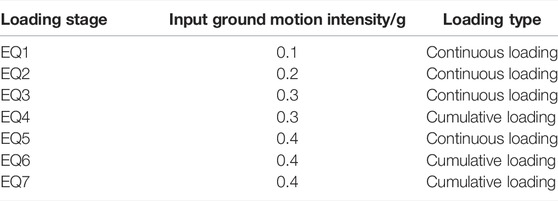
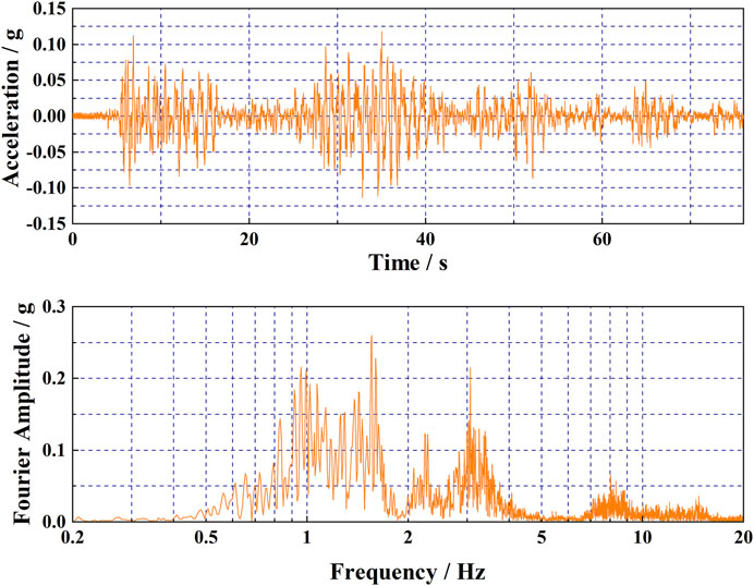
The input ground motion adopted the Qingxi bedrock wave of the Wenchuan earthquake provided by Liu et al. (2013). According to the ground motion loading scheme presented in Table 3, the maximum amplitude range of the input ground motion in seven stages (i.e., EQ1–EQ7) was between 0.1 and 0.4 g. Not only the increase in the seismic intensity at the 0.1-g interval adopted in most studies was considered but also the same intensity (EQ4, EQ6, and EQ7) was set in three stages. As an example, the acceleration time history and Fourier spectrum of A0 at EQ1, with a PGA = 0.118 g, are shown in Figure 2. It is worth noting that the cumulative loading and continuous loading mentioned here only refer to whether the input ground motion peak value is the same as that of the previous stage and does not refer to different loading methods. Its purpose is mainly to enrich the variation of ground motion.
3 Test Results
3.1 Displacement
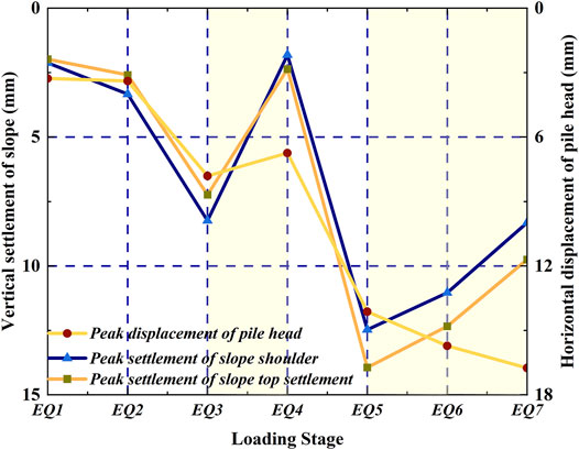
The displacement and settlements of the pile head and slope at each event are presented in Figure 3, where it can be seen that the displacement of the pile head is positive in the direction away from the slope, while the settlement of the slope is positive in the downward direction. The settlement and displacement here refer to the dynamic peak value in the response stage and not the cumulative value. In the whole process, the periodic displacements of the top and the shoulder of the slope show a similar movement trend. When the earthquake intensity increased, the settlement of the slope also increased, but when the intensity was unchanged, the settlement decreased. One possible reason for this change is considered to be that the ground motion of the previous stage makes the slope material more compact, thereby reducing the peak dynamic settlement (displacement) in the next adjacent stage of the same input strength. The slope settlement in the loading growth stage is much larger than that in the adjacent stable stage. Even for EQ6 and EQ7 with high strength, the settlement deformation decreases gradually. It should be stated that the test results in this study are displayed after being converted to the prototype size.
Before EQ5, the variation trend of the pile head’s horizontal displacement with seismic intensity is the same as that of the slope settlement. However, during multiple high-intensity earthquakes (EQ5–EQ7), the pile head displacement continued to increase, even when there is only a small increase. It is worth noting that the first high-intensity earthquake EQ5 causes a more obvious settlement of the slope than earthquakes EQ1–3. Although the subsequent settlement decreased, the settlement is still larger than that of the medium- and low-intensity earthquakes. This also makes the pile body tilt out to resist slope sliding, resulting in a continuous increase in the pile head displacement.
3.2 Slope Amplification
Acceleration measuring points are divided into three groups according to their spatial position, as shown in Figure 4A: Group A (GA) includes three measuring points, which are located behind the pile, representing the upper, middle, and lower parts of the cantilever section of the pile body. Measuring points A4 and A6 are close to the soil rock contact surface and anchor cable, respectively. Group B (GB) comprises measuring points on the slope surface and slope top, where the amplification effect is obvious. Group C (GC) includes the measuring point A9 which is located at the center of the slope and measuring points A8, A11, and A14 which are near the bedrock surface.
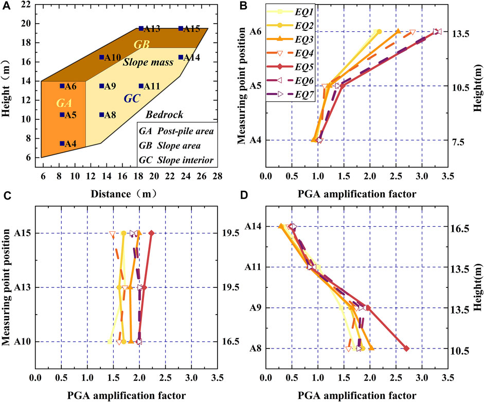
FIGURE 4. PGA amplification factor results: (A) Grouping of acceleration measuring points; (B) the results of GA; (C) the results of GB; and (D) the results of GC.
The variation curve of the amplification factor of GA with elevation is presented in Figure 4B, where it can be seen that the peak ground acceleration (PGA) amplification factor shows a significant elevation amplification effect, which increases with the elevation. With the change in the input ground motion intensity, the change in each measuring point shows different trends. The amplification factor of the measuring points increases with the earthquake intensity but decreases slightly under a high-grade earthquake with the same intensity. The amplification factor of A6 is the largest, especially under high-intensity earthquakes, when it can reach more than 3.0. This is due to the topographic effect, site conditions, and dynamic interaction of the structure and slope.
As shown in Figure 4C, the amplification factor of measuring points in GB also increases with the earthquake intensity but decreases in varying degrees under subsequent earthquakes with the same intensity. The amplification factors of this group are concentrated between 1.25 and 2.25, showing an obvious topographic amplification effect. This is because the measuring points of GB are found near the free surface of the slope surface. The magnification effect becomes more pronounced as the distance from special terrains such as slope corners decreases.
In contrast to general expectations, the acceleration amplification factor of the measuring point on the slope in GC does not increase with the elevation, as shown in Figure 4D. This phenomenon could be attributed to the influence of the slope structure on seismic wave propagation. The reflection and refraction, including the surface and bedrock surface, and the phase difference of the seismic waves during the wave propagation could reduce the acceleration amplification effect to a certain extent. Similar phenomena have been noted by Bouckovalas and Papadimitriou, 2005.
In general, different from the homogenous slope amplification, the slope with a complex soil–rock interface strengthened by a pile–anchor structure is very uneven, and the amplification factor shows strong variability. This means that a quasi-static method may have a higher risk in the seismic design of slopes similar to the model considered in this study because the nonuniformity of the ground motion distribution is not considered (Seed and Whiteman, 1970).
3.3 Structure Response
3.3.1 Dynamic Earth Pressure
The peak value variation of the pile with the earthquake intensities is shown in Figure 5A, where it can be seen that dynamic earth pressure increased with the elevation. T1 near the anchor cable is the largest, and T4 near the bedrock surface is the smallest. With the change in the earthquake intensity, the change law of different measuring points is different. T1 continued to increase, even under the high-strength processes EQ5–EQ7, which could be related to the pile–soil compression caused by anchor cable traction. For other measuring points, at medium and low intensities, the dynamic earth pressure increases and decreases under continuous action of the same intensity. This trend is consistent with the dynamic settlement of the slope. Under large earthquakes (EQ5–EQ7) with a PGA of 0.4 g, the dynamic earth pressure of T2 continues to increase, while that of T3 and T4 either decreases or remains unchanged. This indicates that the pile–soil compression caused by the anchor cable traction decreased with the elevation, but it significantly affected the stress on the upper part of the pile at a high seismic intensity.
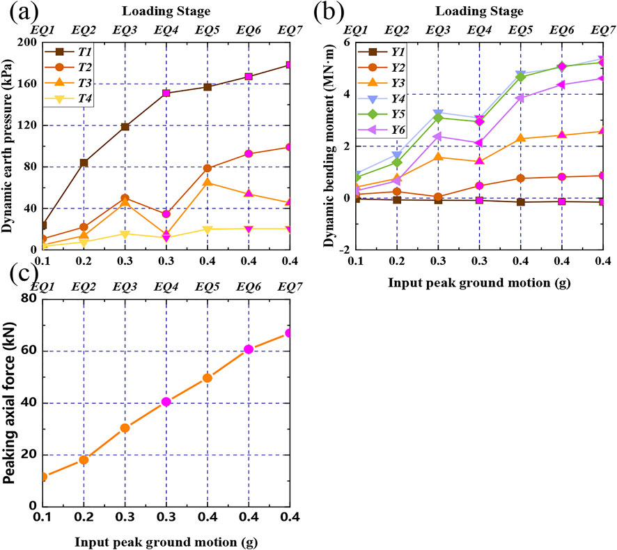
FIGURE 5. Variation curve of the peak value of pile dynamic behavior with input ground motion intensity: (A) The peak dynamic earth pressure of the pile; (B) The peak dynamic bending moment of the pile; (C) The peak axial force of the anchor cable.
3.3.2 Dynamic Bending Moment
The variation curve of the pile dynamic bending moment with seismic intensity is shown in Figure 5B. In this study, the bending moment is positive when the pile body is pulled on the side of the slope. Except for Y1, which has a negative bending moment, the other measuring points have positive bending moments. The dynamic bending moment first increased and then decreased from the pile top to the end, and Y4 reached the maximum in the middle of the pile. The negative bending moment near the anchor cable indicates that the tension of the anchor cable makes the pile deform inward. The variations of different measuring points with the earthquake intensity can be divided into two categories: Y1, where variations continued to increase and are not sensitive to the seismic intensity changes, and the category that included all other measuring points, where variations increase when the earthquake intensity changes but decrease when the earthquake intensity is unchanged.
3.3 3 Anchor Force
The peak axial force of the anchor cable obtained under different seismic events is shown in Figure 5C. Regardless of the seismic intensity being increased or staying unchanged, the peak axial force of the anchor cable always increases and is not sensitive to the input ground motion loading mode. This trend may affect the behavior of the piles near the anchor cable so that the dynamic earth pressure and dynamic bending moment near the anchor cable have similar changing trends.
4 Data Mining Methods
The centrifuge model test results show that there may be some fuzzy correlations between the seismic response of the slope and the behavior of the pile–anchor structure. This ambiguous correlation can be used for data mining by using the gray relational analysis (GRA). Compared with other data mining methods, the gray relational analysis method is equally applicable to the size of the sample and regularity of the sample. Therefore, it is suitable for the analysis and evaluation of a slope under an earthquake, which is limited, complex, and highly uncertain.
4.1 Gray Relational Analysis
GRA is an integral part of the gray system theory. Compared with Pearson’s correlation coefficient, maximum mutual information coefficient (MIC), and other evaluation methods with high requirements for data linearity or sample number, the main advantage of GRA is that it can be used in the case of limited data to determine the correlation between various change and reference factors. The correlation is expressed in gray relational grade, and the greater the gray relational grade is, the better the correlation is. The essence of this method is to explore the correlation between different factors by comparing the similarity of the curves. The specific calculation method is as follows (Deng, 2002):
Let the reference sequence be
where
The gray relational grade can be obtained by averaging the gray relational coefficient, which can be expressed as follows:
4.2 Identification Coefficient Optimization
In Eq. 1, the identification coefficient is usually determined subjectively, and there has been no general solution to the resolution coefficient, which greatly affects the correlation degree value and ranking results, so it is not applicable to most cases. To address this problem, this study further processes data using many improved methods (Xu and Xu, 2011; James et al., 2013; Gao et al., 2018; Ren et al., 2020), which are explained in the following section.
In practical problems, the dimension and order of magnitude of the reference and comparison sequences are usually different, and their effects on the mechanical characteristics of the support structure are also different, which requires further analysis. The usual approach is to normalize data using positive, negative, and other types of normalization. However, such an approach can significantly change the original characteristics of the curve, and the data considered in this study cannot adopt the evaluation criteria of “the larger, the better” or “the smaller, the better.” Therefore, the initial value processing method was adopted for comprehensive consideration, which was given by Gao et al., (2018)
According to Eq. 1, the identification coefficient
where m and n denote the number of comparison sequences and the amount of sequence capacity, respectively.
When
At this point,
4.3 Gray Relational Grade Optimization
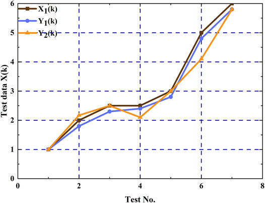
The traditional gray average correlation degree calculation method considers that the sum of gray relational coefficients remains unchanged, ignoring the fact that local similarity is the premise of overall similarity, which can lead to wrong conclusions. The data in Table 4 are taken as examples and drawn in Figure 6. For sequences X1, Y1, and Y2, it can be seen that the development trends of Y1 are much closer to those of X1 than of Y2. However, the gray relational grade of the two is 0.7542 and 0.7544, respectively, indicating the opposite result from the figure and is unreasonable. Therefore, this study selects the gray Euclidean relational grade (Yang et al., 2011) for calculation, which is given by
where
4.4 Comprehensive Discrimination Based on the RSR Method
The gray relational grades of the reference and comparison sequences can be obtained through the fuzzy gray relational grade analysis, however, when the reference sequence changes, the ranking of the gray relational grade may be different and not conducive to comprehensively judging the correlation of the system factors. Fortunately, the rank-sum ratio (RSR) method can effectively carry out a comprehensive discrimination for complex sorting.
The RSR method (Wang et al., 2015) performs an overall ranking based on the dimensionless statistics of 0–1 obtained from the average value of the rank sum of the corresponding comparison sequence under each index. In the experiment, the rank of the same comparison sequence is taken under each relevant reference sequence; the method of summing and taking the average value was used to observe the impact of a group of comparison sequences on the whole. In this way, the problem that the fuzzy gray relational grade had too many results when dealing with the ranking and evaluation of multiple comparison sequences and multiple reference sequences of a whole, which made obtaining the overall view difficult, was solved. In addition, because the gray relational grade only had practical significance in relative comparison and sorting, the disadvantage of losing a certain amount of the original data in the calculation process of the RSR method has also been addressed. The calculation formula of the RSR value is as follows:
where j is the number of evaluated units (or the jth comparison sequence); i is the number of evaluation indicators (or the ith reference sequence); and Rij is the rank of the jth comparison sequence under the ith reference sequence. In particular, the higher the RSR value is, the higher the ranking is.
5 Result Analysis
According to the types of seismic response parameters of the pile–slope-anchor system, the pile head seismic peak displacement (PPERD), peak dynamic bending moment (Y1–Y6), peak dynamic earth pressure (T1–T4), and peak axial force (PC) of the anchor cable are determined as a reference sequence, and the comparison sequence is designated as the PGA amplification factor of the measuring points at different positions, as presented in Table 5. The sample size of each sequence is 7 due to the test events. It is worth noting that the formulation rules of the comparison sequence made the correlation ranking associated with the spatial position of the measuring points. The gray relational grade is calculated by Eqs 1–6. Figure 7 shows the contour maps at some typical points, while the sorting results of all parameters are given in Table 6.
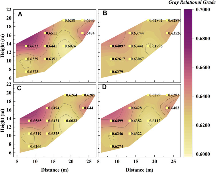
FIGURE 7. Contour map of the gray relational grades at some typical measuring points: (A) The results of PPERD; (B) The results of T1; (C) The results of Y1; (D) The results of PC.
As presented in Figure 7, the distribution of the gray relational grades for different reference sequences shows the same trend. In detail, all the calculation results are greater than zero, and the shape of the isolines is crooked. That means the seismic responses at all positions of the slope contribute to the dynamic behavior of the pile, but the correlations are different, which is related to the position of the acceleration measuring point. The measuring points with a higher comprehensive ranking of correlation are A6, A10, A14, A9, and A8. Among the measuring points, A6 has the largest gray relational grade. It is located where the interaction of slope, vertical free surface, and pile–anchor structure is significant and where the amplification factor is significantly high and abnormal. The peak dynamic earth pressure of the pile near A6 is the largest, and the peak dynamic bending moment shows a reversal from positive to negative. A8–A10 were located in the middle of the slope, and the amplification factors of the three points are greater than those of the surrounding points, especially when the earthquake intensity increased. During the test, obvious cracks between the slope and the bedrock were observed near A14, which could be attributed to the large contact angle. The other measuring points in the ranking have no special phenomenon on the ground motion parameters and slope failure.
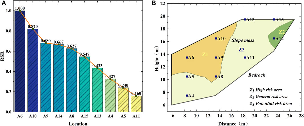
From the model test results, it is not difficult to find that the slope acceleration amplification varied nonlinearly, while it can be divided into three categories according to the maximum, minimum, and median values. The three types of results are shown in Figure 8 as descending orders and can be considered the most dangerous, safest, and relatively moderate seismic action experienced by the slope, respectively. It can be seen that about 60%–70% of the PGA amplification factor obtained by deploying the measuring points is greater than the minimum amplification factor of 1.2, which has been specified in Eurocode 8 (CEN European Committee for standardization, 2003). This indicates that the actual slope seismic response has exceeded the provisions of the specification, which would affect engineering safety. If the seismic design is fully considered according to the maximum acceleration amplification factor, the engineering economy may be unacceptable. Therefore, to comprehensively evaluate the influence of slope amplification on the pile–anchor–slope reinforcement system, the ranking results of the gray relational grade and the classification results of slope acceleration amplification factor should be considered together during the RSR assessment, and the result is shown in Figure 9A.

FIGURE 8. PGA amplification factor ordering: (A–B–C) in the figure is the ranking result of the maximum value, minimum value, and median value of the PGA amplification factor.
Figure 9A shows that the high correlation is related to the high amplification factor and the distance from the measuring point to the pile, which conforms to St. Venant’s principle. In the RSR ranking, A6 and A8–A10 are in the top five, indicating that the high acceleration response inside the slope has a significant contribution to the dynamic behavior of the pile–anchor structure. Except the aforementioned measuring points, A14 ranked fourth, and the large inclination of the bedrock surface near this point is not conducive to the stability of the slope. Although A4 and A5 are close to the pile, the amplification factors are just 1.13–1.47 and 0.92–1.05, respectively. In addition, although the amplification on the slope crest has a limited effect on the reinforced structure, it may influence the structures built on the slope top which has been confirmed by Brennan and Madabhushi (2009).
The RSR ranking results also show that some positions inside the slope need special consideration in seismic design, rather than assuming that the slope is subjected to the consistent seismic force based on the quasi-static method. According to the acceleration amplification effect and RSR ranking result, the slope can be divided into three risk areas, as shown in Figure 9B. The high-risk and potential-risk areas denoted areas where the RSR value is higher than 0.6. The former is the area where the acceleration is significantly amplified, while the latter is related to the slope instability caused by the geometric parameters of the bedrock surface. It may be one of the more possible strategies to add shock absorption materials to high-risk areas with abnormal acceleration amplification. Some 1-g shaker test results suggest that additional shock-absorbing material is a possible treatment (Ma et al., 2019; Pai and Wu, 2021). This can not only eliminate the occurrence of unknown factors to a certain extent but also reduce economic waste. For the potential-risk areas, it is necessary to ensure that the grouting strength of the embedded section of the anchor cable meets the design standard to prevent the anchor cable from being pulled out from the bedrock.
6 Conclusion
To study the correlation between slope amplification and the seismic behavior of the pile, a centrifugal shaking table test was established considering the effect of different seismic intensities, and the slope amplification factor and pile mechanical parameter data of the pile–anchor–slope reinforcement system were obtained. On this basis, combined with the fuzzy gray relational analysis and the rank-sum ratio method, the correlation between the amplification of the acceleration response of the heterogenous slope and the dynamic response of the support structure was explored. Based on the obtained results, relevant suggestions for engineering design were put forward. The main conclusions and suggestions are summarized as follows:
1) The acceleration amplification of the slope body is uneven, the amplification of the pile–anchor cable connection is the largest, and the high-angle soil–rock interface is the smallest. The variation law is consistent, and it increases or decreases with the change of the input ground motion intensity. Slope amplification inhomogeneity may cause actual earthquake damage not to meet the design expectations of the quasi-static method.
2) The peak value of the peak dynamic earth pressure of the pile increases with the increase of the relative elevation and the soil mass is squeezed by the pile-anchor joint, resulting in the largest dynamic earth pressure near the top of the pile, and the smallest T4 near the bedrock surface; the peak dynamic bending moment of the pile is negative near the top of the pile, gradually becomes positive as the elevation decreases, reaches the maximum value near the bedrock surface, and then gradually decreases; except for the continuous increase of the dynamic soil pressure, dynamic bending moment, and peak axial force at the pile–anchor connection, the other measurement points increase when the input ground motion intensity increases but decrease when the input ground motion intensity remains the same.
3) The comprehensive ranking of the FGRA-RSR method shows that the magnification of different positions has different effects on the seismic force of the pile. The positions of the top 50% of the ranking are located in the pile–anchor connection part, the middle of the slope, and the high-angle soil–rock interface. Most of these locations have high soil magnification or have obvious geometric features. Therefore, it is necessary to consider the shock absorption measures of the pile–anchor cable connection and ensure the grouting strength of the anchor cable anchoring section in the actual design.
The research in this article still has some limitations. This mainly focuses on the lack of more available engineering cases and model test data. Undoubtedly, more cases will make the ranking results of the comprehensive evaluation more convincing and can provide more valuable suggestions for engineering practice. Unfortunately, there are, indeed, some objective difficulties. In the follow-up, it may be considered to obtain data in more cases using numerical simulation after calibration based on model tests (Ni et al., 2018; Ni and Mangalathu, 2018; Ni et al., 2020).
Data Availability Statement
The datasets presented in this article are not readily available because they are used only with the consent of the corresponding author of this article. Requests to access the datasets should be directed to ZT, emhlbmd0MDkyOEAxNjMuY29t.
Author Contributions
YW handled most of the work of the article. TZ is the main contributor to guide the revision of the article. Other authors also contributed some suggestions to the article.
Funding
This work was supported by the Scientific Research Fund of Institute of Engineering Mechanics, China Earthquake Administration (Grant Nos 2018B04; 2020B03), the National Natural Science Foundation of China (Grant Nos 51808515; 41874067), the Natural Science Foundation of Heilongjiang Province (Grant No. LH2020E020), and the Hebei Natural Science Foundation of China (Grant No. E2020201017).
Conflict of Interest
The authors declare that the research was conducted in the absence of any commercial or financial relationships that could be construed as a potential conflict of interest.
Publisher’s Note
All claims expressed in this article are solely those of the authors and do not necessarily represent those of their affiliated organizations, or those of the publisher, the editors, and the reviewers. Any product that may be evaluated in this article, or claim that may be made by its manufacturer, is not guaranteed or endorsed by the publisher.
References
Bouckovalas, G. D., and Papadimitriou, A. G. (2005). Numerical Evaluation of Slope Topography Effects on Seismic Ground Motion. Soil Dyn. Earthquake Eng. 25, 547–558. doi:10.1016/j.soildyn.2004.11.008
Brennan, A. J., and Madabhushi, S. P. G. (2009). Amplification of Seismic Accelerations at Slope Crests. Can. Geotech. J. 46, 585–594. doi:10.1139/t09-006
CEN European Committee for Standardization (2003). Design Provisions for Earthquake Resistance of Structures - Part 5: Foundations, Retaining Structures and Geotechnical aspectsEurocode 8 ENV 1998-5. Brussels: CEN European Committee for Standardization.
Chen, G. F., Zhang, G. D., Guo, F., Wang, L., Zhan, Q. H., and Huang, X. H. (2022). New Arm-stretching-type Anti-slide Pile Design and Verification. Front. Earth Sci. 10. Article 846616. doi:10.3389/feart.2022.846616
Cilinger, U., and Madabhushi, S. P. G. (2011). Effect of Depth on Seismic Response of Circular Tunnels. Can. Geotechnical J. 48, 117–127.
Finn, W. D. L., Ledbetter, R. H., and Beratan, L. L. (1986). Seismic Soil-Structure Interaction: Analysis and Centrifuge Model Studies. Nucl. Eng. Des. 94, 53–66. doi:10.1016/0029-5493(86)90153-6
Gao, C.-l., Li, S.-c., Wang, J., Li, L.-p., and Lin, P. (2018). The Risk Assessment of Tunnels Based on Grey Correlation and Entropy Weight Method. Geotech Geol. Eng. 36, 1621–1631. doi:10.1007/s10706-017-0415-5
Garala, T. K., and Madabhushi, G. S. P. (2019). Seismic Behaviour of Soft clay and its Influence on the Response of Friction Pile Foundations. Bull. Earthquake Eng. 17, 1919–1939. doi:10.1007/s10518-018-0508-4
Gazetas, G., Psarropoulos, P. N., Anastasopoulos, I., and Gerolymos, N. (2004). Seismic Behaviour of Flexible Retaining Systems Subjected to Short-Duration Moderately strong Excitation. Soil Dyn. Earthquake Eng. 24, 537–550. doi:10.1016/j.soildyn.2004.02.005
Ghosh, B., and Madabhushi, S. P. G. (2007). Centrifuge Modelling of Seismic Soil Structure Interaction Effects. Nucl. Eng. Des. 237 (8), 887–896. doi:10.1016/j.nucengdes.2006.09.027
Halder, L., Dutta, S. C., Sharma, R. P., and Bhattacharya, S. (2021). Lessons Learnt from post-earthquake Damage Study of Northeast India and Nepal during Last Ten Years: 2021 Assam Earthquake, 2020 Mizoram Earthquake, 2017 Ambasa Earthquake, 2016 Manipur Earthquake, 2015 Nepal Earthquake, and 2011 Sikkim Earthquake. Soil Dyn. Earthquake Eng. 151. Article ID 106990. doi:10.1016/j.soildyn.2021.106990
Heron, C. M., Haigh, S. K., and Madabhushi, S. P. G. (2015). A New Macro-Element Model Encapsulating the Dynamic Moment-Rotation Behaviour of Raft Foundations. Géotechnique 65, 442–451. doi:10.1680/geot.sip.15.p.020
Hu, H. Q., Huang, Y., Xiong, M., and Zhao, L. Y. (2021). Investigation of Seismic Behavior of Slope Reinforced by Anchored Pile Structures Using Shaking Table Tests. Soil Dyn. Earthquake Eng. 150. Article ID 106900. doi:10.1016/j.soildyn.2021.106900
Hu, M. M., Wu, Z. H., Reicherter, K., Ali, S., Huang, X. L., and Zuo, J. M. (2021). A Historical Earthquake-Induced Landslide Damming Event at the Qiaojia Reach of the Jinsha River, SE Tibetan Plateau: Implication for the Seismic Hazard of the Xiaojiang Fault. Front. Earth Sci. 9. Article ID 649543. doi:10.3389/feart.2021.649543
Huang, R. Q., and Li, W. L. (2009). Analysis of the Geo-Hazards Triggered by the 12 May 2008 Wenchuan Earthquake, China. Bull. Eng. Geol. Environ. 68, 363–371. doi:10.1007/s10064-009-0207-0
Huang, Y., Xu, X., Liu, J. J., and Mao, W. W. (2020). Centrifuge Modeling of Seismic Response and Failure Mode of a Slope Reinforced by a Pile-Anchor Structure. Soil Dyn. Earthquake Eng. 131. Article ID 106037. doi:10.1016/j.soildyn.2020.106037
James, N., Liu, K., and Hu, Y. X. (2013). Application of Feature-Weighted Support Vector Regression Using gray Relational Grade to Stock price Forecasting. Neural Comput. Appl. 22 (Suppl. 1), S143–S152.
Liu, H., Bo, J., Li, P., Qi, W., and Zhang, Y. (2016). Site Amplification Effects as an Explanation for the Intensity Anomaly in the Hanyuan Town during the Wenchuan M W 7.9 Earthquake. Earthq. Eng. Eng. Vib. 15, 435–444. doi:10.1007/s11803-016-0334-0
Liu, H. S., Yang, J. B., Bo, J. S., and Liu, Y. (2013). Bedrock Ground Motion Input to High-Intensity Abnormality Area in Hanyuan County Town during Wenchuan Ms 8.0 Earthquake. J. Earthquake Eng. Eng. Vibration 33 (2), 27–36.
Liu, X. L., Yan, J. K., T, B., and Liu, L. (2021). Evaluation of Micropiles with Different Configuration Settings for Landslide Stabilization Based on Large-Scale Experimental Testing. Front. Earth Sci. 9. Article 693639. doi:10.3389/feart.2021.693639
Liu, X. L., Zhang, Z. M., and Zhou, D. P. (2004). Improved Calculation Method of Prestressed Anchor cable Anti Slide Pile. Chin. J. Rock Mech. Eng. 23 (15), 2568–2572. (in Chinese).
Ma, N., Wu, H., Ma, H., Wu, X., and Wang, G. (2019). Examining Dynamic Soil Pressures and the Effectiveness of Different Pile Structures inside Reinforced Slopes Using Shaking Table Tests. Soil Dyn. Earthquake Eng. 116, 293–303. doi:10.1016/j.soildyn.2018.10.005
Ni, P., and Mangalathu, S. (2018). Fragility Analysis of gray Iron Pipelines Subjected to Tunneling Induced Ground Settlement. Tunnelling Underground Space Tech. 76, 133–144. doi:10.1016/j.tust.2018.03.014
Ni, P., Mangalathu, S., and Liu, K. (2020). Enhanced Fragility Analysis of Buried Pipelines through Lasso Regression. Acta Geotech. 15, 471–487. doi:10.1007/s11440-018-0719-5
Ni, P., Mangalathu, S., and Yi, Y. (2018). Fragility Analysis of Continuous Pipelines Subjected to Transverse Permanent Ground Deformation. Soils and Foundations 58, 1400–1413. doi:10.1016/j.sandf.2018.08.002
Ni, P. P., Song, L. H., Mei, G. X., and Zhao, Y. L. (2017). On Predicting Displacement-dependent Earth Pressure for Laterally Loaded Piles. Soil and Foundations 58 (1), 85–96.
Pai, L. F., and Wu, H. G. (2021). Shaking Table Test of Comparison and Optimization of Seismic Performance of Slope Reinforcement with Multi-Anchor Piles. Soil Dyn. Earthquake Eng. 145. Article ID 106737. doi:10.1016/j.soildyn.2021.106737
Psarropoulos, P. N., Klonaris, G., and Gazetas, G. (2005). Seismic Earth Pressures on Rigid and Flexible Retaining walls. Soil Dyn. Earthquake Eng. 25, 795–809. doi:10.1016/j.soildyn.2004.11.020
Ren, S. J., Wang, C. P., and Xiao, Y. (2020). Thermal Properties of Coal during Low Temperature Oxidation Using a gray Relational Method. Fuel 260. Article ID 116287. doi:10.1016/j.fuel.2019.116287
Seed, H. B., and Whiteman, R. V. (1970). “Design of Earth Retaining Structures for Dynamic Load,”in Lateral Stresses in the Ground and Design of Earth Retaining Structures. ASCE, 103–147.s
Su, Y. H., Luo, Z. D., and Li, X. (2012). Gray Relational Analysis Method for Cut-And-Fill Roadbed Slope Stability Based on Uniform experiment. Rock Soil Mech. 33 (8), 2259–2264.
Sun, Z., Kong, L., Guo, A., and Alam, M. (2020). Centrifuge Model Test and Numerical Interpretation of Seismic Responses of a Partially Submerged deposit Slope. J. Rock Mech. Geotechnical Eng. 12, 381–394. doi:10.1016/j.jrmge.2019.06.012
Veletsos, A. S., and Younan, A. H. (1997). Dynamic Response of Cantilever Retaining Walls. J. Geotechnical Geoenvironmental Eng. 123 (2), 161–172. doi:10.1061/(asce)1090-0241(1997)123:2(161)
Wang, G. X. (1998). Present Situation of Landslide Control Engineering Measures at home and Abroad. Chin. J. Geol. Hazard Control. 9 (1), 1–9. (in Chinese).
Wang, Z., Dang, S., Xing, Y., Li, Q., and Yan, H. (2015). Applying Rank Sum Ratio (RSR) to the Evaluation of Feeding Practices Behaviors, and its Associations with Infant Health Risk in Rural Lhasa, Tibet. Ijerph 12 (12), 15173–15181. doi:10.3390/ijerph121214976
Xu, J., and Xu, Y. (2011). Grey Correlation-Hierarchical Analysis for Metro-Caused Settlement. Environ. Earth Sci. 64, 1249–1256. doi:10.1007/s12665-011-0940-0
Yan, K. M., He, J. S., and Cheng, Q. G. (2020). A Centrifuge Experimental Investigation on the Seismic Response of Group-Pile Foundation in a Slope with an Inclined Weak Intercalated Layer. Soil Dyn. Earthquake Eng. 130. Article ID 105961. doi:10.1016/j.soildyn.2019.105961
Yang, L. B., Gao, Y. Y., and Ling, W. X. (2011). Principle and Application of Fuzzy Mathematics. Guangzhou: South China University of Technology Press.
Zelikson, A., Leguay, P., and Pascal, C. (1983). Centrifugal Model Analysis of Pile and Raft Foundations Subject to Earthquakes. Int. J. Soil Dyn. Earthquake Eng. 2 (4), 222–227. doi:10.1016/0261-7277(83)90039-6
Zhang, J., Qu, H., Liao, Y., and Ma, Y. (2012). Seismic Damage of Earth Structures of Road Engineering in the 2008 Wenchuan Earthquake. Environ. Earth Sci. 65, 987–993. doi:10.1007/s12665-011-1519-5
Zhao, B., Wang, Y. S., Wang, Y., Shen, T., and Zhai, Y. C. (2017). Retaining Mechanism and Structural Characteristics of H Type Anti-slide Pile (hTP Pile) and Experience with its Engineering Application. Eng. Geology. 222, 29–37.
Zheng, T., Liu, H. S., Yuan, X. M., and Qi, W. H. (2016). Experimental Study on Seismic Response of Anti-slide Piles with Anchor Cables by Centrifuge Shaking Table. Chin. J. Rock Mech. Eng. 35 (11), 2276–2286.
Keywords: centrifuge shaking table test, anchored stabilizing pile, fuzzy gray relational grade, rank sum ratio method, data mining
Citation: Wang Y, Zheng T, Sun R, Qi W and Qi W (2022) Influence of Slope Amplification on the Pile Dynamic Behavior Based on the Data Mining Method. Front. Earth Sci. 10:885586. doi: 10.3389/feart.2022.885586
Received: 28 February 2022; Accepted: 04 April 2022;
Published: 03 May 2022.
Edited by:
Chong Xu, Ministry of Emergency Management, ChinaReviewed by:
Rajeswari J. S, National Institute of Technology, Andhra Pradesh, IndiaYazdan Shams Maleki, Kermanshah University of Technology, Iran
Pengpeng Ni, Sun Yat-sen University, China
Copyright © 2022 Wang, Zheng, Sun, Qi and Qi. This is an open-access article distributed under the terms of the Creative Commons Attribution License (CC BY). The use, distribution or reproduction in other forums is permitted, provided the original author(s) and the copyright owner(s) are credited and that the original publication in this journal is cited, in accordance with accepted academic practice. No use, distribution or reproduction is permitted which does not comply with these terms.
*Correspondence: Tong Zheng, emhlbmd0MDkyOEAxNjMuY29t
 Yu Wang
 Tong Zheng
