
94% of researchers rate our articles as excellent or good
Learn more about the work of our research integrity team to safeguard the quality of each article we publish.
Find out more
METHODS article
Front. Earth Sci., 08 April 2022
Sec. Solid Earth Geophysics
Volume 10 - 2022 | https://doi.org/10.3389/feart.2022.883160
This article is part of the Research TopicLithospheric Diversity: New Perspective on Structure, Composition and EvolutionView all 14 articles
 Yingjie Gao1,2
 Meng-Hua Zhu1,2*
The perfectly matched layer (PML) is one of the most popular absorbing boundary conditions for simulating seismic waves. In theory, the PML can absorb incident waves at any incident angle and any frequency in a medium. However, numerical reflections will be generated after the PML has been discretized. Therefore, how to reduce the reflections of discrete PML has been a research topic for more than 2 decades. In this paper, we adopt the reflectionless discrete PML (RD-PML) for seismic wave and implement the RD-PML based on the acoustic wave equation, and then compare its absorbing performance with that of the conventional discrete PML. Our numerical experiments show that the RD-PML has advantages over the conventional discrete PML. In homogeneous model, a thick enough RD-PML can effectively eliminate reflections. In heterogeneous model, a thin-layer RD-PML can obtain better absorbing performance even than the thick-layer conventional discrete PML. The absorbing performance of the RD-PML can be improved by using the periodic boundary without increasing the amount of computation and memory. RD-PML provides a new perspective to understand the discretization of PML, and may play an important role in promoting the development of PML technology.
Perfectly matched layer (PML) is one of the most widely used artificial absorbing boundaries that are used to deal with the artificial boundary truncation in the numerical simulation of seismic wave propagation. It was proposed by Bérenger (1994) for electromagnetic wave simulations, and was applied to the wave equation using complex coordinate stretching through the modification of spatial partial derivatives, which introduces an imaginary part of the coordinate that is associated with an attenuation factor (Chew and Weedon, 1994). After its introduction, the PML found widespread use in various fields of numerical simulation due to its good applicability to different types of equations. For example, it is commonly implemented for seismic wave simulation (Chew and Liu, 1996), which includes both the acoustic wave simulation (Liu and Tao, 1997; Yuan et al., 1997; Qi and Geers, 1998; Katsibas and Antonopoulos, 2002; Diaz and Joly, 2006; Bermúdez et al., 2007; Ma et al., 2014) and the elastic wave simulation (Chew and Liu, 1996; Hastings et al., 1996; Collino and Tsogka, 2001; Komatitsch and Tromp, 2003; Pled and Desceliers, 2021).
In theory, the PML can absorb the incident waves of any incident angle and any frequency under continuous medium. However, numerical reflections will still be generated after the PML has been discretized. In order to improve the absorbing performance of discrete PML, several methods have been proposed, which are briefly reviewed in the following paragraphs.
Collino and Monk (1998) optimized the discrete PML by suitable design of the layer, which includes the selection for the number of layers and attenuation coefficients. After that, people carried out further optimization work to choose the layer parameters of PML (Fang and Wu, 1996; Winton and Rappaport, 2000; Travassos et al., 2006; Bermúdez et al., 2007; Nissen and Kreiss, 2011).
The absorbing performance of the discrete PML is proven to vary with the angle of the incident wave, and will continue to decrease as the angle of the incident wave gradually increases (Gao et al., 2017); thus its absorbing performance on grazing incident waves is not satisfactory (Roden and Gedney, 2000; Winton and Rappaport, 2000). Furthermore, the grazing incident waves can be converted into evanescent waves, which cannot be absorbed by the PML and will generate spurious reflections (Drossaert and Giannopoulos, 2007b; Komatitsch and Martin, 2007). Kuzuoglu and Mittra (1996) modified the PML by introducing two new parameters to the complex coordinate stretching operator of PML, which can shift the pole of the complex coordinate stretched operator to a non-zero value. The modified PML is called as complex frequency-shifted PML (CFS-PML), and can improve the absorbing performance of the PML for grazing incident waves (Festa and Vilotte, 2005, Komatitsch and Martin, 2007, Drossaert and Giannopoulos, 2007a, b).
The PML and CFS-PML were both originally implemented based on split-field formulations, which adopts a nonphysical splitting of the variables in the wave equations and lead to two different sets of equations for the inner wavefield simulation area and the outer PML area. Furthermore, the split-field formulation is mathematically weakly well-posed (Abarbanel and Gottlieb, 1997), and will be unstable for long time simulations (Festa et al., 2005). Different unsplit-field implementations of the CFS-PML were developed by using convolutional algorithms (Roden and Gedney, 2000; Wang and Tang, 2003; Wang et al., 2005; Drossaert and Giannopoulos, 2007a, b; Komatitsch and Martin, 2007; Li and Matar, 2010; Pasalic and McGarry, 2010; Matzen, 2011), integral terms (Zeng and Liu, 2004; Drossaert and Giannopoulos, 2007b), matched Z-transform (Shi et al., 2012), and auxiliary differential-equation (ADE) algorithm (Ramadan, 2003; Rejiba et al., 2003; Wang and Liang, 2006; Kristek et al., 2009; Gedney and Zhao, 2010; Martin et al., 2010; Zhang and Shen, 2010; Xie et al., 2014; Deng et al., 2018; He et al., 2019). Among the above methods, the convolutional algorithm and the ADE algorithm are the most widely used in seismic numerical simulations. The ADE algorithm is implemented by introducing auxiliary differential equations, which are a series of first-order partial derivative equations; in contrast, the convolutional algorithm is implemented by convolutional operations, which are solved by recursive convolution technique (Luebbers and Hunsberger, 1992).
For an isotropic medium, the unsplit CFS-PML will be a sufficient choice for long time simulation because of its weak reflections and excellent stability (Komatitsch and Martin, 2007), but in an anisotropic viscoelastic medium, the unsplit CFS-PML suffers from instabilities for long-time simulation. The multi-axial PML (M-PML) was developed to guarantee the long-time stability of PML in an anisotropic medium, which is efficient and stable without dependences on frequencies and directions of wave propagation (Meza-Fajardo and Papageorgiou, 2008, 2010, 2012; Ping et al., 2014, 2016; Gao and Huang, 2017). But it was soon proven that the M-PML is not perfectly matched and thus is not a PML (Dmitriev and Lisitsa, 2011, 2012). Rather, it can be seen as an improved sponge boundary (Xie et al., 2014).
The numerical implementations of the traditional PML and CFS-PML are based on the first-order system of wave equations, and they cannot be directly applied to the second-order wave equation. The second-order wave equation is usually transformed into the first-order form to just to be able to use the PML or CFS-PML, which significantly increases both the memory requirement and computational cost (Liu and Tao, 1997; Yuan et al., 1997; Qi and Geers, 1998; Yuan et al., 1999). Komatitsch and Tromp (2003) were the first to try and construct the PML for the second-order elastic wave equation, and a series of studies were followed (Pasalic and McGarry, 2010; Duru and Kreiss, 2012; Ma et al., 2014; Xie et al., 2014; Gao et al., 2015; Ma et al., 2018, 2019a, 2019b).
It was shown that the CFS-PML could be understood as a low-pass Butterworth filter, which can absorb waves with frequency higher than the cut-off frequency, but cannot efficiently absorb low-frequency waves below the cut-off frequency (Festa and Vilotte, 2005). To absorb both the low-frequency propagating waves and evanescent waves, high-order CFS-PML was proposed (Correia and Jin, 2005, 2006). Unlike the conventional CFS-PML (or called the first-order CFS-PML) that only has a single pole in the coordinate stretching operator, the higher-order CFS-PML has multiple poles that consist of two or more stretching operators. The higher-order CFS-PML has the advantages of both the conventional PML and the CFS-PML in terms of absorbing performance, since the conventional PML is great at the low frequencies but poor at grazing incidences, while the CFS-PML is poor at low frequencies but great at grazing incidences (Martin et al., 2010; Feng and Li, 2013). Feng et al. (2015) proved that the second-order PML is an optimal choice, since it provides almost the same absorbing performance as the third-order PML, while requiring less computational time and memory. Feng et al. (2017) analyzed the different roles of the second-order CFS-PML parameters and proposed optimal selections of these parameters to get satisfactory results for broad-band seismic wave simulations.
The above-mentioned research works have continuously promoted the development of PML technology, both in terms of absorbing performance and realization form. However, none of them has achieved “mechanical zero” absorbing performance after discretization. Chern (2019) presented a new approach to deriving the discrete PML equations using Discrete Complex Analysis (Duffin, 1956; Lovász, 2004; Bobenko et al., 2005; Bobenko and Günther, 2016). Instead of seeking a high-order discretization of the continuous PML equations, Chern (2019) took the discrete wave equation and found its associated PML equations by mimicking the continuous theory but solely in the discrete setting. The resulted discrete PML for the first time “perfectly matches” the discrete wave equation, and it is called reflectionless discrete PML (RD-PML). Furthermore, Chern (2019) proposed to use a constant attenuation coefficient to replace the conventional gradually increasing attenuation coefficients. The RD-PML gained good absorbing performance, but it was originally proposed based on a homogeneous model with the velocity
In this paper, we adopt the RD-PML to solve the boundary truncation problem for acoustic equation modelling. Firstly, we briefly introduce the RD-PML algorithm and give the attenuation coefficient with arbitrary velocity v. The model design for periodic boundary is also discussed. Then, we compare the absorbing performance of RD-PML with that of the conventional discrete PML, and verify the improvement effect of the periodic boundary on the absorbing performance. The case of heterogenous model is also considered. Numerical experiments demonstrate the superiority of RD-PML method over conventional methods.
We start with the 2-dimensional acoustic wave equation
where
To implement the PML, the spatial partial derivative in the wave equation can be extended to complex coordinate by the stretching operator (Johnson, 2008):
where
The expression for the complex coordinate is
The plane wave solution can be expressed as
where
After further sorting, Eq. 6 can be written as
Compared with the original expression of the plane wave solution in Eq. 5, Eq. 7 has an extra item
where
With a positive wavenumber
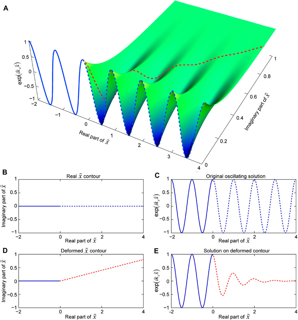
FIGURE 1. Sketch map of the attenuation principle for the plane waves in the PML region. The coordinate that corresponds to
In theory, the PML can absorb the incident waves of any angle and any frequency before discretization (Bérenger, 1994; Komatitsch and Martin, 2007). However, after the discretization, the numerical reflections will arise at the interface of PML due to the discretization error (Bérenger, 2002; Gao et al., 2017). Here, we analyse why the conventional discrete PML will produce reflected waves. The corresponding discrete format complex coordinate path for
which is shown by the blue line in Figure 2A. The finite-difference (FD) operators for the spatial partial derivative
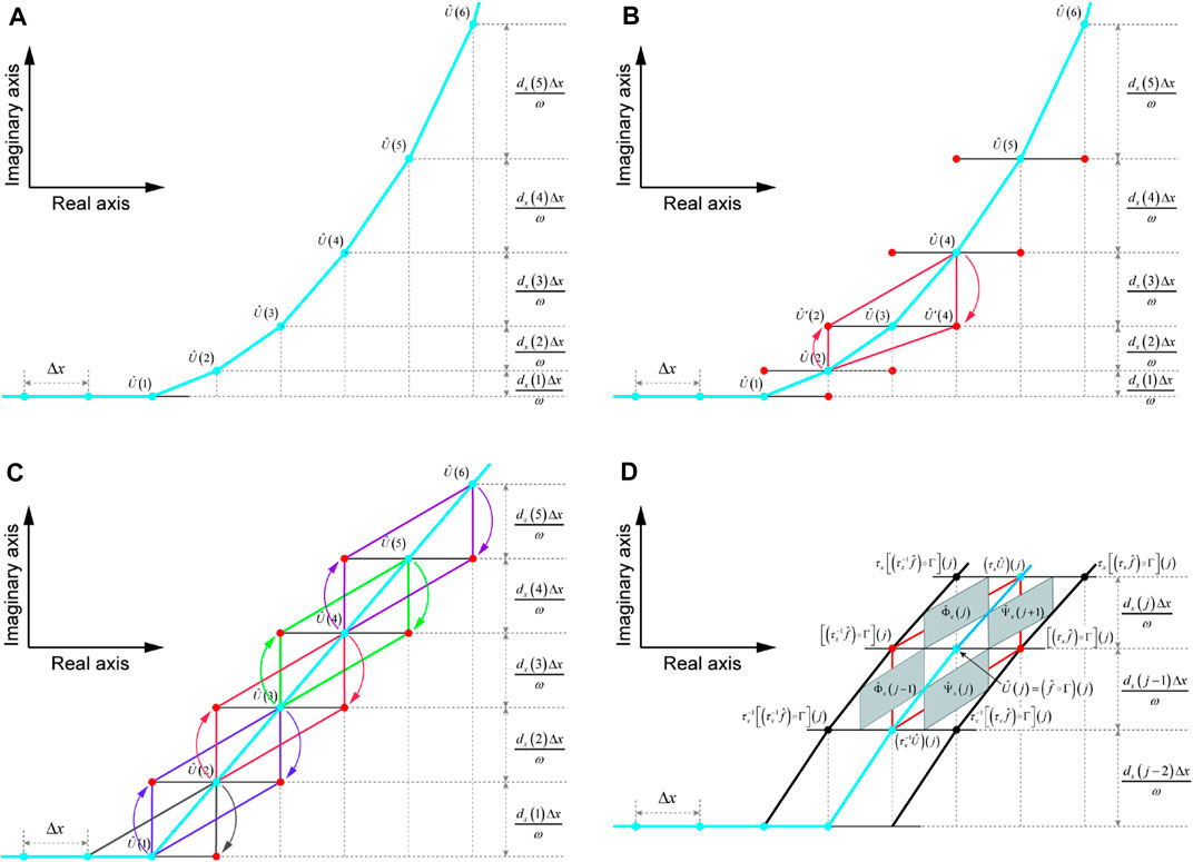
FIGURE 2. Sketch map of the stretching path for the PML in the complex coordinate after discretization and sketch map of the projection method using discrete complex analysis. (A) The discrete stretching path for the PML in the complex coordinate using gradually increasing attenuation coefficients. (B) The quadrilateral for the projection using discrete complex analysis for the discrete path in (A). (C) The discrete stretching path for the PML in the complex coordinate using constant attenuation coefficients. The quadrilaterals of different colors represent the projection quadrilaterals of the 2nd-order FD operator corresponding to the respective center points. (D) Sketch map the projection method of the quadrilateral corresponding to
Chern (2019) presented the reflectionless discrete PML (abbreviated as RD-PML) using Discrete Complex Analysis (Duffin, 1956; Lovász, 2004; Bobenko et al., 2005; Bobenko and Günther, 2016), and this new form discrete PML for the first time “perfectly matches” the discrete wave equation. For example, the FD operator at
Furthermore, Chern (2019) proposed to use a constant attenuation coefficient to replace the conventional gradually increasing attenuation coefficients. In the example given by Chern (2019), the constant attenuation coefficient is
The
Smooth waves with 0 incident angle can be eliminated within one grid when
With the constant attenuation coefficient, the projection method is shown as Figure 2C, the quadrangles with different colours mean different projection unit for each 2nd-order FD operator. Figure 2D, which refers to Chern (2019), shows the projection method for the quadrangle of
Further, the expression of
Now, we can convert the 2nd-order FD operator for the spatial partial derivative
Substituting Eq. 15 into the latter expression of Eq. 16, we can obtain
where the attenuation term of the RD-PML is simply added to the original FD operator. This form does not require special treatment of the original wave equation to implement the RD-PML, and we only need to add the corresponding attenuation term in the PML attenuation area during programming, which is very convenient for the realization of numerical simulation.
After transforming Eqs 14, 17 back to the time domain using the inverse Fourier transform, and introducing the derivation along the z-direction, we can obtain the whole expressions of the RD-PML for Eq. 1:
where
In a homogeneous medium, since the PML attenuation coefficient of each layer is the same, Chern (2019) adopted the periodic boundary, which greatly improved the absorbing performance of the RD-PML. Figure 3 shows the sketch map of the periodic boundary. Figure 3A1 shows the conventional Dirichlet boundary for 2nd-order FD scheme in 1-dimansional situation, while Figure 3A2 shows the corresponding periodic boundary processing method, which connects the outmost FD operators on the two sides of discrete grid points. Figure 3B shows the sketch maps of the periodic boundary condition in the two-dimensional model, in which Figures 3B1, 3B2 with the boundaries set in the four directions of up, down, left, and right and Figure 3B3, 3B4 with the free boundary condition for the up boundary and the PML for the other three boundaries. Neither the top boundary nor the bottom boundary has been specially processed, and the periodic boundaries are only used for the left and right boundaries.
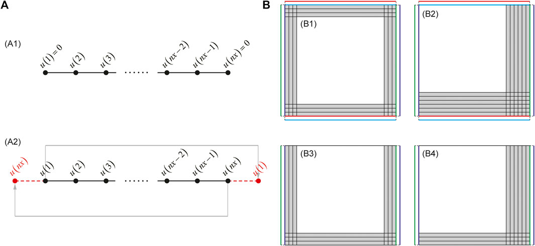
FIGURE 3. Sketch map of the periodic boundary condition. (a1) The conventional aperiodic boundary condition for 1-dimensional model. (a2) The periodic boundary condition for 1-dimensional model. (B) Sketch map of the periodic boundary condition for 2-dimensional model. (b1) and (b2) are the sketch map of the periodic boundaries settled in the four directions of up, down, left, and right. (b3) and (b4) are the sketch map of the periodic boundary condition with the free boundary condition for the up boundary and the PML boundaries for the other three directions. periodic boundary is used only for the left and right boundaries.
We perform numerical experiments on a homogeneous square model using different types of PML. The wave velocity is v = 3,000 m/s. The spatial grid interval is Δx = Δz = 10 m, and the grid number is 301 × 301. The source is a Ricker wavelet with a dominant frequency of 15 Hz, which is located at the center of the square model. We use the 2nd-order FD method for the spatial discretization and 4-stage Runge Kutta method for the temporal discretization, and the time step is Δt = 1 ms. We compare the boundary reflections using various types of PML: the AED CFS-PML using collocated grid (abbreviated as CFS-PML-1, Gao et al., 2015) with 20 layers; the convolutional CFS-PML using staggered grid (abbreviated as CFS-PML-2, Pasalic and McGarry, 2010) with 20 layers; and the RD-PML with 10 layers and 20 layers, respectively. We use a very large model to simulate the theoretical wavefield to avoid boundary reflections, which can be regarded as a reference to check the performance of the above-mentioned artificial absorbing boundaries.
Figure 4 shows the snapshots obtained by different types of PML. At 550 ms, the wavefield has not reached the attenuation area of PML, and the reflected waves have not yet arisen, so the value of the reflections in Figure 4B1–4B4 are all zero. At 750 ms, conspicuous reflections appear in 20-layer CFS-PML-1, and weak reflections appear in 20 CFS-PML-2. This is because the latter one is implemented based on the staggered grid method, and its absorbing performance is better than that of the former one, which is implemented based on the collocated grid method. Neither 10-layer RD-PML nor 20-layer RD-PML shows any reflections in the current color scale. At 1,000 ms, there are slight reflections in 10-layer RD-PML, but there are still no visible reflections in 20-layer RD-PML. At the same time, by comparing the reflections of 10-layer RD-PML with that of 20-layer CFS-PML-1 and 20-layer CFS-PML-2, we find that the reflected waves of the conventional discrete PML (20-layer CFS-PML-1 and 20-layer CFS-PML-2) mainly consist of two parts: one part is the reflected wave from the inner boundary of PML, and the other is the reflected wave from the outer boundary of PML.
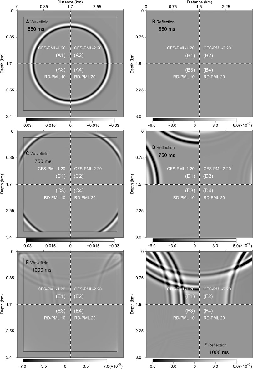
FIGURE 4. Snapshots and wave reflections obtained using different types of PML. (A), (C), and (E) are the snapshots obtained at 550, 750, and 1,000 ms, respectively. The areas in the black boxes are the normal wavefield simulation area, and the areas outside the black boxes are the absorbing area of PML. (B), (D), and (F) are the wave reflections obtained at 550, 750, and 1,000 ms in the normal wavefield simulation area, respectively.
The reflections of 10-layer RD-PML mainly consist of the reflected waves from the outer boundary, which is caused by the outer boundary of PML due to insufficient thickness. Considering that the parameter settings of each layer of 10-layer RD-PML and 20-layer RD-PML are all the same, which also explains why the latter performs better than the former. At the same time, this conclusion leads to experiments using periodic boundaries.
Figure 5 shows the snapshots obtained by different types of PML after the periodic boundaries used. After adopting the periodic boundaries refer to Figure 3B1, the reflections from outer boundary of the conventional discrete PML (20-layer CFS-PML-1 and 20-layer CFS-PML-2) have been significantly reduced; while the reflections from inner boundary of the conventional discrete PML have not changed (as shown in Figure 5F). This is because the periodic boundary can be regarded as a thickening of the original boundary, which cannot improve the absorbing performance of the reflections from the inner boundary and can only improve the absorbing performance of the reflections from the outer boundary. As analyzed above, the reflections of the 10-layer RD-PML mainly consist of the reflections from the outer boundary. Therefore, its absorbing performance has been significantly improved after adopting the periodic boundary. The reflected waves of 10-layer RD-PML are no longer visible in the color scale of Figure 5F.
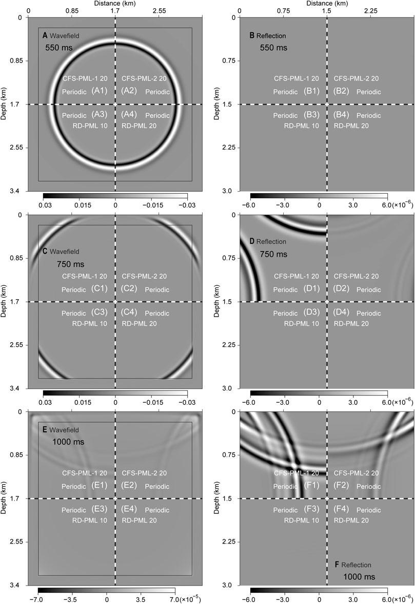
FIGURE 5. Snapshots and wave reflections obtained using different types of PML using periodic boundary. (A), (C), and (E) are the snapshots obtained at 550, 750, and 1,000 ms, respectively. (B), (D), and (F) are the wave reflections obtained at 550, 750, and 1,000 ms, respectively.
Figure 6 shows the waveforms along the horizontal dashed lines in Figures 4, 5. Figure 6A shows the waveforms for different types of PML before reaching the boundaries, and all the unattenuated waveforms are all the same. Figures 6D,F are the logarithmic displays for the reflected waves of Figures 6C,E, respectively. At 1,000 ms, the reflected waves of the 10-layer RD-PML are the smallest among all the reflections (shown in Figure 6F). At the same time, we find that the reflected waves of the 20-layer RD-PML, periodic 10-layer RD-PML, and periodic 20-layer RD-PML all disappear. This is because their reflections are zero and the corresponding logarithmic values don’t exist, which demonstrate that the absorbing performance of these three boundaries indeed reach “mechanical zero” (Chern, 2019).
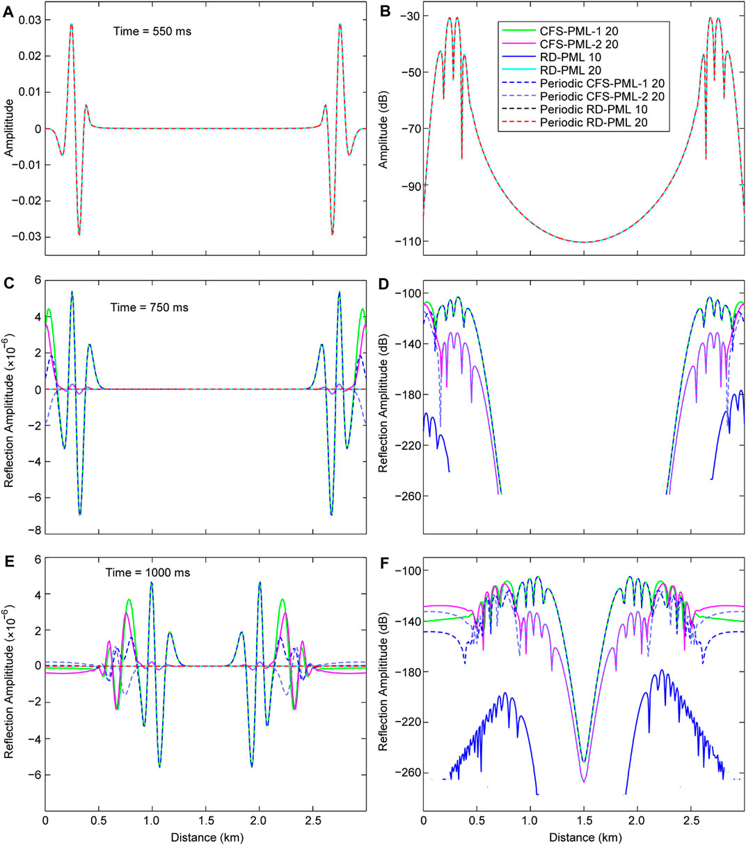
FIGURE 6. Waveforms along the horizontal dashed line in Figure 4 and Figure 5 at different time. (A), (C), and (E) are the waveforms obtained at 550, 750, and 1,000 ms, respectively. (B), (D), and (F) are the logarithmic display of waveforms in (A). (C), and (E), respectively.
For the convenience of comparing the absorbing performances of different boundary conditions, we further perform numerical experiments using a long model, which can be seen as a narrow strip model (shown in Figure 7A). The farther the distance between the receiver and the seismic source, the greater the incident angle of the wave field, and the harder it is to absorb the incident waves for the absorbing boundary. Grazing incident wave would appear in the long model when the wavefield is far from the source (Komatitsch and Martin, 2007; Gao et al., 2017), so we can compare the absorbing performance for the grazing incident wave of different PML. The wave velocity is v = 3,000 m/s. The spatial grid interval is Δx = Δz = 10 m, and the grid number is 601 × 81. The source is a Ricker wavelet with a dominant frequency of 10 Hz. Seismic source is located at 1,000 m along x-direction and 100 m in depth. We obtain the wavefield records along the line composed of blue inverted triangles in Figure 7A. We use a very large model to simulate the theoretical wavefield records to avoid boundary reflections, which can be regarded as a reference (shown in Figure 7B).
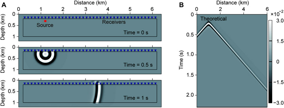
FIGURE 7. Schematic map of the narrow slice model and wave field record. (A) Snapshots of a point source for the narrow slice model at 0, 500, and 1,000 ms. The snapshots are obtained by 20-layer RD-PML. (B) Shot records by the receivers along the horizontal line of blue triangles in (A). The shot records are obtained using a very large model to avoid boundary reflections, which can be regarded as a reference to check the performance of different types of PML.
Figure 8 shows the wavefield difference between the shot records of different types of PML with the theoretical shot records that shown in Figure 7B. For absorbing the grazing incident waves, 10-layer RD-PML performs better than 20-layer CFS-PML-1 and 20-layer CFS-PML-2 (shown in Figures 8A,B), but performs not as good as Periodic 20-layer CFS-PML-1 and Periodic 20-layer CFS-PML-2 (shown in Figures 8E,F). Weak reflected waves appear in 20-layer RD-PML (shown in Figure 8D), while no obvious reflected waves appear in Periodic 10-layer RD-PML and Periodic 20-layer RD-PML (shown in Figures 8D,H).
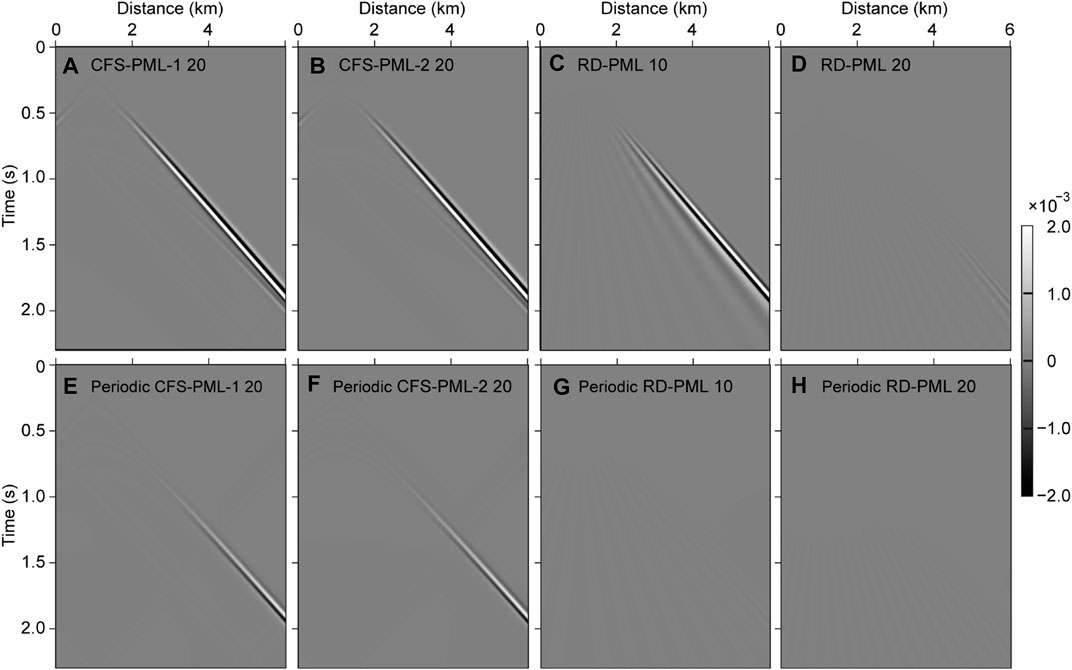
FIGURE 8. Wavefield difference between the shot records of different types of PML with the theoretical shot records that shown in Figure 7B. (A), (B), (C), and (D) are the wavefield difference between the shot records of 20-layer CFS-PML-1, 20-layer CFS-PML-2, 10-layer RD-PML, and 20-layer RD-PML with the theoretical records, respectively. (E), (F), (G), and (H) are the wavefield difference that the shot records using periodic boundaries for the corresponding types of PML in (A), (B), (C), and (D), respectively.
Because RD-PML still uses the conventional PML coordinate stretching operator expression (shown as Eq. 2), broom-like evanescent waves still appear (shown in Figures 8C,D,G,H), which are caused by grazing incident waves. Due to the advantages of the coordinate stretching operator expression of CFS-PML type boundary for grazing waves (Komatitsch and Martin, 2007), no broom-like reflected wave appears (shown in Figures 8A,B,E,F). Compared with the main reflected waves, the evanescent waves are very weak and their amplitudes are negligible. The RD-PML here, especially after adopting the periodic absorbing boundary, has obvious advantages over conventional methods.
In order to further compare the absorbing performances, we calculated the numerical reflection coefficients for different types of PML. We calculate the numerical reflection coefficient by
where
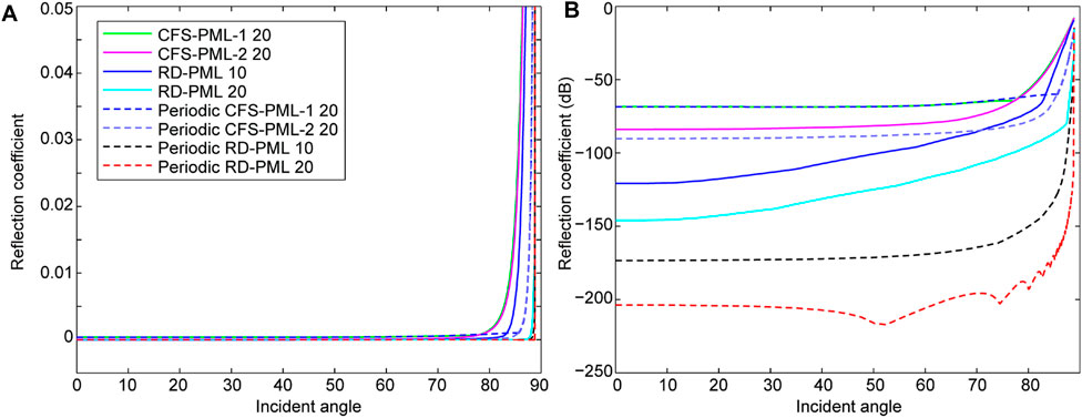
FIGURE 9. Comparison of the reflection coefficient computed by numerical simulations. (A) Absolute values of numerical reflection coefficient. (B) The decibel (dB) values of numerical reflection coefficient.
Obviously, the periodic boundary performs better than the corresponding non-periodic boundary. Periodic-10-layer RD-PML performs even better than 20-layer RD-PML, and periodic 20-layer RD-PML performs the best among all the absorbing boundaries. The jitters in the reflection curve of periodic 20-layer RD-PML is caused by the broom-like evanescent waves in Figure 8H, whose amplitudes are negligible.
To illustrate the numerical performance of the proposed method for heterogeneous media, we test on the modified Marmousi model, as shown in Figure 10A. The grid spacing is 10 m and the grid number is 737 × 751. The upper boundary of the model is a free surface, and the other three edges are absorbing boundaries. The source is a Ricker wavelet and the dominant frequency is of 8 Hz. The source is added on the free surface and middle of the model. A group of receivers are located along the upper boundary. Eight kinds of boundary conditions are compared. There is no theoretical wavefield available as a reference for the Marmousi model; thus, we take the wavefield generated by 50-layer RD-PML as a reference instead (shown in Figure 10B). The periodic boundaries for different types of PML are settled refer to Figure 3B3.
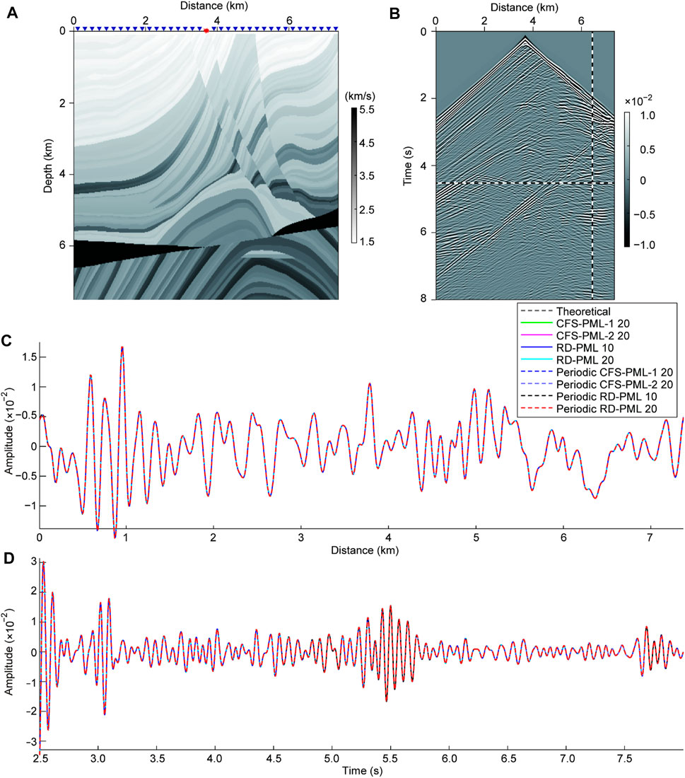
FIGURE 10. Numerical test on a heterogeneous model. (A) Modified Marmousi model. (B) Shot records by the receivers along the horizontal line of blue triangles in (A). (C) and (D) are the waveforms along the horizontal dashed line and the vertical dashed line in (B), respectively.
Figure 11 shows the wavefield difference, which can be regarded as the reflected waves from the boundaries, between the shot records of different types of PML with the reference shot records that shown in Figure 10B. Figures 12A, B show the waveforms along the horizontal dashed line and the vertical dashed line in Figure 11, respectively. The performances of 10-layer RD-PML are better than that of 20-layer conventional CFS-PML, which demonstrates that RD-PML still has a good absorbing effect and applicability for heterogeneous media. Here we focus on the internal comparison of different layers of RD-PML. There are two points that require special analysis: 1) periodic 10-layer RD-PML performs better than 10-layer RD-PML, but not better than 20-layer RD-PML, which is different from the homogeneous medium. Taking the left and right boundaries as an example, the speed setting of the PML region is a one-dimensional extension of the speed along the outermost boundary of the model. Though we set a constant attenuation coefficient
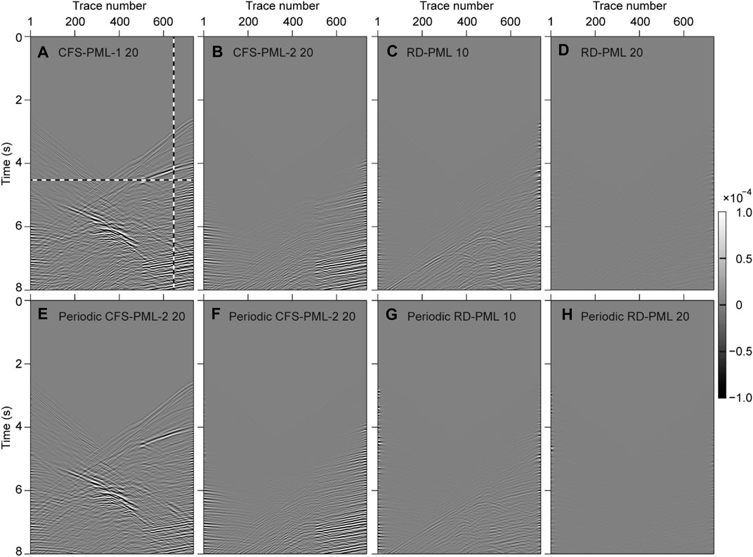
FIGURE 11. Wavefield difference between the shot records of different types of PML with the reference shot records that shown in Figure 10B. (A), (B), (C), and (D) are the wavefield difference between the shot records of 20-layer CFS-PML-1, 20-layer CFS-PML-2, 10-layer RD-PML, and 20-layer RD-PML with the theoretical records, respectively. (E), (F), (G), and (H) are the wavefield difference that the shot records using periodic boundaries for the corresponding types of PML in (A), (B), (C), and (D), respectively.
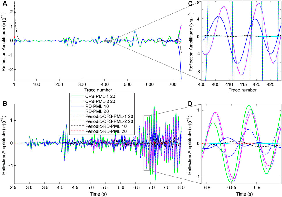
FIGURE 12. Artificial reflections obtained by the wavefield difference between the shot records and the reference shot records. (A) and (B) are the waveforms along the horizontal dashed line and the vertical dashed line in Figure 11, respectively. (C) and (D) are the enlarged portions of the frame in (A) and (B), respectively.
In summary, the improvement of the absorbing performance in heterogeneous media by the periodic boundary is not as obvious as in a homogeneous medium both for the conventional discrete PML and the RD-PML, but RD-PML is still superior to the conventional discrete PML. Considering that there is almost no increase in the amount of calculation, we recommend the use of RD-PML with periodic boundary.
The expression of the coordinate stretching operator used in this article (shown as Eq. 2) has a sign difference compared with the regular expression (Collino and Tsogka, 2001; Komatitsch and Martin, 2007; Zhang and Shen, 2010; Gao et al., 2017):
This is because that Eq. 2 is proposed based on the plane wave expression:
The RD-PML is implemented by directly adding the decay terms to the original wave equation and the original spatial partial derivatives have not been modified (shown as the first expression in Eq. 18), which is very easy for programming. In addition, since RD-PML is suitable for periodic boundary, the scheme in Figures 3B2, 3B4 can be used in programming, which is very easy to load RD-PML outside the normal simulation area. These two advantages make RD-PML have good application prospects in both reverse time migration (RTM) and full waveform inversion (FWI). To implement the RD-PML for an existing RTM or FWI program, we don’t have to rewrite the original program; instead, we only need to add a corresponding RD-PML calculation module and load it in the main program.
For the temporal discretization, we tried to implement the RD-PML using the conventional 2nd-order FD method for the temporal discretization. However, a very small time-step size is required to ensure the stability of the wave field iteration, otherwise the wavefield iteration would fail. Instead, we adopt the 4-stage Runge Kutta method for the temporal discretization of the seismic wave equation according to Chern (2019). We give a rough analysis for the reason here. The stability area of the 4-stage Runge Kutta method is larger than that of the second-order FD method (shown in Figure 13), which means that the CFL stability condition of the former are more relaxed (Karim, 1966; Frank, 2008). In the case of the same spatial model parameters, the former can use a larger time step, and we can use the time step as we routinely use for simulation. This shows that the stability conditions of the RD-PML method are relatively harsh, although it has been proven to be stable by Chern (2019). The research on the stability conditions of RD-PML can also be a future research work.
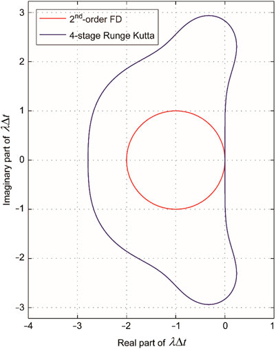
FIGURE 13. Stability regions for different temporal discretization methods. The stability regions for the 2nd-order FD scheme and the 4-stage Runge Kutta scheme are the regions inside the red curve and the blue curve, respectively; while the instability regions for the 2nd-order FD scheme and the 4-stage Runge Kutta scheme are the regions outside the red curve and the blue curve, respectively.
We introduce the RD-PML to the seismic wave numerical simulation. Firstly, we introduce the principle of PML attenuation in detail and analyze the cause of reflections that produced by conventional discrete PML. Then, we compare the absorbing performance of the RD-PML with that of the conventional discrete PML. Numerical experiments demonstrate the superiority of the RD-PML. In homogenous model, RD-PML with sufficient thickness (e.g., 20 layer) can make the reflected waves reach the effect of mechanical zero; in heterogenous model, 10-layer RD-PML performs better than the 20-layer conventional discrete PML. Furthermore, we adopt periodic boundary to the RD-PML, which can improve the absorbing performance of RD-PML without increasing the amount of memory and calculation. Although in the inhomogeneous medium, the periodic boundary has a very limited improvement in the absorbing performance, it doesn’t increase the amount of calculation. Another point is that RD-PML is directly implemented based on the 2nd-order equation, and the attenuation term is directly added to the original wave equation. This kind of system does not need to be rewritten as a first-order system, which is very convenient for programming. The method in this paper provides a new idea to realize discrete PML, and has an important role in promoting the development of PML technology.
The raw data supporting the conclusion of this article will be made available by the authors, without undue reservation.
YG derives the equations, writes the program, and does the numerical experiments. MZ checks the formula derivation and takes analysis for the numerical experiments.
The authors declare that the research was conducted in the absence of any commercial or financial relationships that could be construed as a potential conflict of interest.
All claims expressed in this article are solely those of the authors and do not necessarily represent those of their affiliated organizations, or those of the publisher, the editors, and the reviewers. Any product that may be evaluated in this article, or claim that may be made by its manufacturer, is not guaranteed or endorsed by the publisher.
We are especially grateful to Albert Chern for his helpful introduction and discussion on RD-PML. This research is supported by the Science and Technology Development Fund, Macau SAR (grant nos. 0002/2019/APD, 0079/2018/A2). YG is also supported by the National Natural Science Foundation of China (grant no. 41704063, 11773087) and the General Financial Grant from the China Postdoctoral science foundation (grant no. 2017M610980).
Abarbanel, S., and Gottlieb, D. (1997). A Mathematical Analysis of the PML Method. J. Comput. Phys. 134 (2), 357–363. doi:10.1006/jcph.1997.5717
Bérenger, J. P. (1994). A Perfectly Matched Layer for the Absorption of Electromagnetic Waves. J. Comput. Phys. 114 (2), 185–200. doi:10.1006/jcph.1994.1159
Bérenger, J. P. (2002). Numerical Reflection from FDTD-PMLs: A Comparison of the Split PML with the Unsplit and CFS PMLs. IEEE Trans. Antennas Propag. 50 (3), 258–265. doi:10.1109/8.999615
Bermúdez, A., Hervella-Nieto, L., and Prieto, A. (2007). An Optimal Perfectly Matched Layer with Unbounded Absorbing Function for Tim/j.jcp.2006.09.018
Bobenko, A. I., and Günther, F. (2016). “Discrete Complex Analysis on Planar Quad-Graphs,” in Advances in Discrete Differential Geometry (Berlin, Heidelberg: Springer), 57–132. doi:10.1007/978-3-662-50447-5_2
Bobenko, A. I., Mercat, C., and Suris, Y. B. (2005). Linear and Nonlinear Theories of Discrete Analytic Functions. Integrable Structure and Isomonodromic Green's Function. J. für die reine Angew. Math. (Crelles J.) 2005, 117–161. doi:10.1515/crll.2005.2005.583.117
Chern, A. (2019). A Reflectionless Discrete Perfectly Matched Layer. J. Comput. Phys. 381, 91–109. doi:10.1016/j.jcp.2018.12.026
Chew, W. C., and Liu, Q. H. (1996). Perfectly Matched Layers for Elastodynamics: a New Absorbing Boundary Condition. J. Comp. Acous. 04 (04), 341–359. doi:10.1142/s0218396x96000118
Chew, W. C., and Weedon, W. H. (1994). A 3D Perfectly Matched Medium from Modified Maxwell's Equations with Stretched Coordinates. Microw. Opt. Technol. Lett. 7 (13), 599–604. doi:10.1002/mop.4650071304
Collino, F., and Monk, P. B. (1998). Optimizing the Perfectly Matched Layer. Comput. Methods Appl. Mech. Eng. 164 (1-2), 157–171. doi:10.1016/s0045-7825(98)00052-8
Collino, F., and Tsogka, C. (2001). Application of the Perfectly Matched Absorbing Layer Model to the Linear Elastodynamic Problem in Anisotropic Heterogeneous media. Geophysics 66 (1), 294–307. doi:10.1190/1.1444908
Correia, D., and Jian-Ming Jin, J.-M. (2005). On the Development of a Higher-Order PML. IEEE Trans. Antennas Propagat. 53 (12), 4157–4163. doi:10.1109/tap.2005.859901
Correia, D., and Jin, J.-M. (2006). Performance of Regular PML, CFS-PML, and Second-Order PML for Waveguide Problems. Microw. Opt. Technol. Lett. 48 (10), 2121–2126. doi:10.1002/mop.21872
Deng, C., Luo, M., Yuan, M., Zhao, B., Zhuang, M., and Liu, Q. H. (2018). The Auxiliary Differential Equations Perfectly Matched Layers Based on the Hybrid SETD and PSTD Algorithms for Acoustic Waves. J. Theor. Comput. Acoust. 26 (1), 1–19. doi:10.1142/s2591728517500311
Diaz, J., and Joly, P. (2006). A Time Domain Analysis of PML Models in Acoustics. Comput. Methods Appl. Mech. Eng. 195 (29), 3820–3853. doi:10.1016/j.cma.2005.02.031
Dmitriev, M. N., and Lisitsa, V. V. (2011). Application of M-PML Reflectionless Boundary Conditions to the Numerical Simulation of Wave Propagation in Anisotropic media. Part I: Reflectivity. Numer. Analys. Appl. 4 (4), 271–280. doi:10.1134/s199542391104001x
Dmitriev, M. N., and Lisitsa, V. V. (2012). Application of M-PML Absorbing Boundary Conditions to the Numerical Simulation of Wave Propagation in Anisotropic media. Part II: Stability. Numer. Analys. Appl. 5 (1), 36–44. doi:10.1134/s1995423912010041
Drossaert, F. H., and Giannopoulos, A. (2007a). Complex Frequency Shifted Convolution PML for FDTD Modelling of Elastic Waves. Wave Motion 44 (7), 593–604. doi:10.1016/j.wavemoti.2007.03.003
Drossaert, F. H., and Giannopoulos, A. (2007b). A Nonsplit Complex Frequency-Shifted PML Based on Recursive Integration for FDTD Modeling of Elastic Waves. Geophysics 72 (2), T9–T17. doi:10.1190/1.2424888
Duffin, R. J. (1956). Basic Properties of Discrete Analytic Functions. Duke Math. J. 23 (2), 335–363. doi:10.1215/s0012-7094-56-02332-8
Duru, K., and Kreiss, G. (2012). A Well-Posed and Discretely Stable Perfectly Matched Layer for Elastic Wave Equations in Second Order Formulation. Commun. Comput. Phys. 11 (5), 1643–1672. doi:10.4208/cicp.120210.240511a
Fang, J., and Wu, Z. (1996). Closed-form Expression of Numerical Reflection Coefficient at PML Interfaces and Optimization of PML Performance. IEEE Microw. Guid. Wave Lett. 6 (9), 332–334. doi:10.1109/75.535836
Feng, N., and Li, J. (2013). Novel and Efficient FDTD Implementation of Higher-Order Perfectly Matched Layer Based on ADE Method. J. Comput. Phys. 232 (1), 318–326. doi:10.1016/j.jcp.2012.08.012
Feng, N., Yue, Y., Zhu, C., Wan, L., and Liu, Q. H. (2015). Second-order PML: Optimal Choice of Nth-Order PML for Truncating FDTD Domains. J. Comput. Phys. 285, 71–83. doi:10.1016/j.jcp.2015.01.015
Feng, H., Zhang, W., Zhang, J., and Chen, X. (2017). Importance of Double-Pole CFS-PML for Broad-Band Seismic Wave Simulation and Optimal Parameters Selection. Geophys. J. Int. 209 (2), 1148–1167. doi:10.1093/gji/ggx070
Festa, G., and Vilotte, J.-P. (2005). The Newmark Scheme as Velocity-Stress Time-Staggering: an Efficient PML Implementation for Spectral Element Simulations of Elastodynamics. Geophys. J. Int. 161 (3), 789–812. doi:10.1111/j.1365-246x.2005.02601.x
Festa, G., Delavaud, E., and Vilotte, J. P. (2005). Interaction between Surface Waves and Absorbing Boundaries for Wave Propagation in Geological Basins: 2D Numerical Simulations. Geophys. Res. Lett. 32, 1–4. doi:10.1029/2005gl024091
Frank, J. (2008). Numerical Modelling of Dynamical Systems. Lecture Notes. URL: https://webspace.science.uu.nl/∼frank011/Classes/numwisk/ (Accessed 2008).
Gao, K., and Huang, L. (2017). Optimal Damping Profile Ratios for Stabilization of Perfectly Matched Layers in General Anisotropic media. Geophysics 83 (1), T15–T30. doi:10.1190/geo2017-0430.1
Gao, Y., Zhang, J., and Yao, Z. (2015). Unsplit Complex Frequency Shifted Perfectly Matched Layer for Second-Order Wave Equation Using Auxiliary Differential Equations. J. Acoust. Soc. Am. 138 (6), EL551–EL557. doi:10.1121/1.4938270
Gao, Y., Song, H., Zhang, J., and Yao, Z. (2017). Comparison of Artificial Absorbing Boundaries for Acoustic Wave Equation Modelling. Explor. Geophys. 48 (1), 76–93. doi:10.1071/eg15068
Gedney, S. D., and Zhao, B. (2010). An Auxiliary Differential Equation Formulation for the Complex-Frequency Shifted PML. IEEE Trans. Antennas Propagat. 58 (3), 838–847. doi:10.1109/tap.2009.2037765
Hastings, F. D., Schneider, J. B., and Broschat, S. L. (1996). Application of the Perfectly Matched Layer (PML) Absorbing Boundary Condition to Elastic Wave Propagation. J. Acoust. Soc. Am. 100 (5), 3061–3069. doi:10.1121/1.417118
He, Y., Chen, T., and Gao, J. (2019). Unsplit Perfectly Matched Layer Absorbing Boundary Conditions for Second-Order Poroelastic Wave Equations. Wave Motion 89, 116–130. doi:10.1016/j.wavemoti.2019.01.004
Johnson, S. G. (2008). “Notes on Perfectly Matched Layers (PMLs),” in Lecture Notes (Massachusetts: Massachusetts Institute of Technology), 29.
Karim, A. I. A. (1966). Stability of the Fourth Order runge-kutta Method for the Solution of Systems of Differential Equations. Comput. J. 9 (3), 308–311. doi:10.1093/comjnl/9.3.308
Katsibas, T. K., and Antonopoulos, C. S. (2002). “An Efficient PML Absorbing Medium in FDTD Simulations of Acoustic Scattering in Lossy media,” in Proceedings of the 2002 IEEE Ultrasonics Symposium (Munich, Germany: IEEE).
Komatitsch, D., and Martin, R. (2007). An Unsplit Convolutional Perfectly Matched Layer Improved at Grazing Incidence for the Seismic Wave Equation. Geophysics 72 (5), SM155–SM167. doi:10.1190/1.2757586
Komatitsch, D., and Tromp, J. (2003). A Perfectly Matched Layer Absorbing Boundary Condition for the Second-Order Seismic Wave Equation. Geophys. J. Int. 154 (1), 146–153. doi:10.1046/j.1365-246x.2003.01950.x
Kristek, J., Moczo, P., and Galis, M. (2009). A Brief Summary of Some PML Formulations and Discretizations for the Velocity-Stress Equation of Seismic Motion. Stud. Geophys. Geod. 53 (4), 459–474. doi:10.1007/s11200-009-0034-6
Kuzuoglu, M., and Mittra, R. (1996). Frequency Dependence of the Constitutive Parameters of Causal Perfectly Matched Anisotropic Absorbers. IEEE Microw. Guid. Wave Lett. 6 (12), 447–449. doi:10.1109/75.544545
Li, Y., and Bou Matar, O. (2010). Convolutional Perfectly Matched Layer for Elastic Second-Order Wave Equation. J. Acoust. Soc. Am. 127 (3), 1318–1327. doi:10.1121/1.3290999
Liu, Q., and Tao, J. (1997). The Perfectly Matched Layer for Acoustic Waves in Absorptive media. J. Acoust. Soc. Am. 102 (4), 2072–2082. doi:10.1121/1.419657
Lovász, L. (2004). Discrete Analytic Functions: an Exposition. Surv. Differ. Geom. 9 (1), 241–273. doi:10.4310/SDG.2004.v9.n1.a7
Luebbers, R. J., and Hunsberger, F. (1992). FDTD for Nth-Order Dispersive Media. IEEE Trans. Antennas Propagat. 40 (11), 1297–1301. doi:10.1109/8.202707
Ma, Y., Yu, J., and Wang, Y. (2014). A Novel Unsplit Perfectly Matched Layer for the Second-Order Acoustic Wave Equation. Ultrasonics 54, 1568–1574. doi:10.1016/j.ultras.2014.03.016
Ma, X., Yang, D., Huang, X., and Zhou, Y. (2018). Nonsplit Complex-Frequency Shifted Perfectly Matched Layer Combined with Symplectic Methods for Solving Second-Order Seismic Wave Equations—Part 1: Method. Geophysics 83 (6), 1–49. doi:10.1190/geo2017-0603.1
Ma, X., Yang, D., He, X., Huang, X., and Song, J. (2019a). Nonsplit Complex-Frequency-Shifted Perfectly Matched Layer Combined with Symplectic Methods for Solving Second-Order Seismic Wave Equations—Part 2: Wavefield Simulations. Geophysics 84 (3), T167–T179. doi:10.1190/geo2018-0349.1
Ma, X., Li, Y., and Song, J. (2019b). A Stable Auxiliary Differential Equation Perfectly Matched Layer Condition Combined with Low-Dispersive Symplectic Methods for Solving Second-Order Elastic Wave Equations. Geophysics 84 (4), T193–T206. doi:10.1190/geo2018-0572.1
Martin, R., Komatitsch, D., Gedney, S. D., and Bruthiaux, E. (2010). A High-Order Time and Space Formulation of the Unsplit Perfectly Matched Layer for the Seismic Wave Equation Using Auxiliary Differential Equations (ADE-PML). Comput. Model. Eng. Sci. (Cmes) 56 (1), 17–41.
Matzen, R. (2011). An Efficient Finite Element Time-Domain Formulation for the Elastic Second-Order Wave Equation: A Non-split Complex Frequency Shifted Convolutional PML. Int. J. Numer. Meth. Engng. 88 (10), 951–973. doi:10.1002/nme.3205
Meza-Fajardo, K. C., and Papageorgiou, A. S. (2008). A Nonconvolutional, Split-Field, Perfectly Matched Layer for Wave Propagation in Isotropic and Anisotropic Elastic media: Stability Analysis. Bull. Seismol. Soc. Am. 98 (4), 1811–1836. doi:10.1785/0120070223
Meza-Fajardo, K. C., and Papageorgiou, A. S. (2010). On the Stability of a Non-convolutional Perfectly Matched Layer for Isotropic Elastic media. Soil Dyn. Earthquake Eng. 30 (3), 68–81. doi:10.1016/j.soildyn.2009.09.002
Meza-Fajardo, K. C., and Papageorgiou, A. S. (2012). Study of the Accuracy of the Multiaxial Perfectly Matched Layer for the Elastic-Wave Equation. Bull. Seismol. Soc. Am. 102 (6), 2458–2467. doi:10.1785/0120120061
Nissen, A., and Kreiss, G. (2011). An Optimized Perfectly Matched Layer for the Schrödinger Equation. Commun. Comput. Phys. 9 (1), 147–179. doi:10.4208/cicp.010909.010410a
Pasalic, D., and McGarry, R. (2010). “Convolutional Perfectly Matched Layer for Isotropic and Anisotropic Acoustic Wave Equations,” in Paper read at 80th Annual International Meeting (Denver, CO: Society of Exploration Geophysicists). doi:10.1190/1.3513453
Ping, P., Zhang, Y., and Xu, Y. (2014). A Multiaxial Perfectly Matched Layer (M-PML) for the Long-Time Simulation of Elastic Wave Propagation in the Second-Order Equations. J. Appl. Geophys. 101 (1), 124–135. doi:10.1016/j.jappgeo.2013.12.006
Ping, P., Zhang, Y., Xu, Y., and Chu, R. (2016). Efficiency of Perfectly Matched Layers for Seismic Wave Modeling in Second-Order Viscoelastic Equations. Geophys. J. Int. 207 (3), 1367–1386. doi:10.1093/gji/ggw337
Pled, F., and Desceliers, C. (2021). Review and Recent Developments on the Perfectly Matched Layer (PML) Method for the Numerical Modeling and Simulation of Elastic Wave Propagation in Unbounded Domains. Arch. Comput. Methods Eng. 29, 471–518. doi:10.1007/s11831-021-09581-y
Qi, Q., and Geers, T. L. (1998). Evaluation of the Perfectly Matched Layer for Computational Acoustics. J. Comput. Phys. 139 (1), 166–183. doi:10.1006/jcph.1997.5868
Ramadan, O. (2003). Auxiliary Differential Equation Formulation: an Efficient Implementation of the Perfectly Matched Layer. IEEE Microw. Wireless Compon. Lett. 13 (2), 69–71. doi:10.1109/lmwc.2003.808706
Rejiba, F., Camerlynck, C., and Mechler, P. (2003). FDTD-SUPML-ADE Simulation for Ground-Penetrating Radar Modeling. Radio Sci. 38 (1), 5-1–5-13. doi:10.1029/2001rs002595
Roden, J. A., and Gedney, S. D. (2000). Convolution PML (CPML): An Efficient FDTD Implementation of the CFS-PML for Arbitrary media. Microw. Opt. Technol. Lett. 27 (5), 334–339. doi:10.1002/1098-2760(20001205)27:5<334::aid-mop14>3.0.co;2-a
Shi, R., Wang, S., and Zhao, J. (2012). An Unsplit Complex-Frequency-Shifted PML Based on matchedZ-Transform for FDTD Modelling of Seismic Wave Equations. J. Geophys. Eng. 9 (2), 218–229. doi:10.1088/1742-2132/9/2/218
Travassos, X. L., Avila, S. L., Prescott, D., Nicolas, A., and Krahenbuhl, L. (2006). Optimal Configurations for Perfectly Matched Layers in FDTD Simulations. IEEE Trans. Magn. 42 (4), 563–566. doi:10.1109/tmag.2006.871471
Wang, L., and Liang, C. (2006). A New Implementation of CFS‐PML for ADI‐FDTD Method. Microwave Opt. Technol. Lett. 48 (10), 1924–1928. doi:10.1002/mop.21816
Wang, T., and Tang, X. (2003). Finite‐Difference Modeling of Elastic Wave Propagation: A Nonsplitting Perfectly Matched Layer Approach. Geophysics 68 (5), 1749–1755. doi:10.1190/1.1620648
Wang, Y., Wang, J., and Zhang, D. (2005). Application of CPML to Truncate the Open Boundaries of Cylindrical Waveguides in 2.5-dimensional Problems. Sci. China Ser. F 48 (5), 656–669. doi:10.1360/04yf0186
Winton, S. C., and Rappaport, C. M. (2000). Specifying PML Conductivities by Considering Numerical Reflection Dependencies. IEEE Trans. Antennas Propagat. 48 (7), 1055–1063. doi:10.1109/8.876324
Xie, Z., Komatitsch, D., Martin, R., and Matzen, R. (2014). Improved Forward Wave Propagation and Adjoint-Based Sensitivity Kernel Calculations Using a Numerically Stable Finite-Element PML. Geophys. J. Int. 198 (3), 1714–1747. doi:10.1093/gji/ggu219
Yuan, X., Borup, D., Wiskin, J. W., Berggren, M., Eidens, R., and Johnson, S. A. (1997). Formulation and Validation of Berenger's PML Absorbing Boundary for the FDTD Simulation of Acoustic Scattering. IEEE Trans. Ultrason. Ferroelect., Freq. Contr. 44 (4), 816–822. doi:10.1109/58.655197
Yuan, X., Borup, D., Wiskin, J., Berggren, M., and Johnson, S. A. (1999). Simulation of Acoustic Wave Propagation in Dispersive media with Relaxation Losses by Using FDTD Method with PML Absorbing Boundary Condition. IEEE Trans. Ultrason. Ferroelect., Freq. Contr. 46 (1), 14–23. doi:10.1109/58.741419
Zeng, Y. Q., and Liu, Q. H. (2004). A Multidomain PSTD Method for 3D Elastic Wave Equations. Bull. Seismol. Soc. Am. 94 (3), 1002–1015. doi:10.1785/0120030103
Keywords: absorbing boundary, perfectly matched layer, discrete complex analysis, periodic boundary, boundary reflection
Citation: Gao Y and Zhu M- (2022) Application of the Reflectionless Discrete Perfectly Matched Layer for Acoustic Wave Simulation. Front. Earth Sci. 10:883160. doi: 10.3389/feart.2022.883160
Received: 24 February 2022; Accepted: 09 March 2022;
Published: 08 April 2022.
Edited by:
Weijia Sun, Institute of Geology and Geophysics (CAS), ChinaCopyright © 2022 Gao and Zhu. This is an open-access article distributed under the terms of the Creative Commons Attribution License (CC BY). The use, distribution or reproduction in other forums is permitted, provided the original author(s) and the copyright owner(s) are credited and that the original publication in this journal is cited, in accordance with accepted academic practice. No use, distribution or reproduction is permitted which does not comply with these terms.
*Correspondence: Meng-Hua Zhu, bWh6aHVAbXVzdC5lZHUubW8=
Disclaimer: All claims expressed in this article are solely those of the authors and do not necessarily represent those of their affiliated organizations, or those of the publisher, the editors and the reviewers. Any product that may be evaluated in this article or claim that may be made by its manufacturer is not guaranteed or endorsed by the publisher.
Research integrity at Frontiers

Learn more about the work of our research integrity team to safeguard the quality of each article we publish.