 Liang Zhang
 Fujun Niu1*
 Minghao Liu
 Xin Ju
94% of researchers rate our articles as excellent or good
Learn more about the work of our research integrity team to safeguard the quality of each article we publish.
Find out more
ORIGINAL RESEARCH article
Front. Earth Sci. , 04 April 2022
Sec. Geohazards and Georisks
Volume 10 - 2022 | https://doi.org/10.3389/feart.2022.879332
This article is part of the Research Topic Rock Landslide Risk Assessment, Stability Analysis and Monitoring for The Development of Early Warning Systems and Reinforcement Measures View all 24 articles
Bedded sandstone is classified as sedimentary rock, which is a typical bedded rock with obvious layered structure characteristics. Bedded rocks formed different bedding orientations in the long and complicated geological tectonic evolution and thus have anisotropic mechanical characteristics. Therefore, the strength anisotropy of bedded sandstone depends on the bedding dip angles. In this study, the fracture characteristics and strength criterion of bedded sandstone were studied by triaxial compression tests on rock specimens with different bedding dip angles under different confining pressure. The test results show that the failure mode and strength of the bedded sandstone are related to the bedding dip angles, showing obvious anisotropy. The experimental data are broadly in line with the Jaeger’s surface of weakness (JPW) model. However, considering the difference in the strength of sandstone specimens with horizontal bedding dip (β = 0°) and vertical bedding dip (β = 90°), an improved JPW model is proposed to distinguish the strength criteria for the aforementioned differences. On the basis of considering the nonlinear relationship between confining pressure and rock strength, the JPW model is improved accordingly to make it suitable for predicting the strength behavior of bedded rocks.
There is a long tradition of research on the structure of rocks. In the Earth’s lithosphere, the main components are magmatic rocks, metamorphic rocks, and sedimentary rocks. The sedimentary rocks with a special bedded structure are distributed in two-thirds of the natural land (Blenkinsop, 2000). Rocks show anisotropy on micro- and macroscales. The combination of rock components and mineral aggregates has a great influence on the anisotropy of rock mechanics. Therefore, when considering the mechanical properties of rock, it is necessary to take into account its structural type. In practical engineering application, a set of comprehensive physical and mechanical parameters for a certain range of rock is usually proposed for designing calculation, but the relationship between anisotropy of rock and the condition of multiple engineering forces is rarely considered (Cheng et al., 2015). The anisotropic characteristics of the rock have a great impact on civil engineering, mining, oil exploration, nuclear waste storage, and other projects (Li et al., 2018; Winn et al., 2019; Hu et al., 2021; Zhang et al., 2021). As shown in Figure 1A, for tunnel engineering, the angle between the direction of tunnel axis and the bedding orientations has a great influence on the failure mode of the surrounding rock and the bearing mode of the supporting structure after tunnel excavation. As shown in Figures 1B,C, in order to evaluate the stability of bedded rock slopes with two different bedding orientations, the physical and mechanical parameters used for strength and deformation analysis should be analyzed according to the bedding orientations of rock.
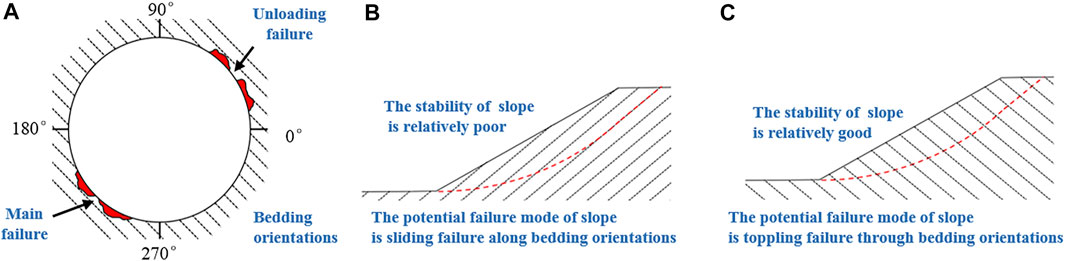
FIGURE 1. Influence of the anisotropy of rock mass on the tunnel failure mode and the stability of slope. (A) Failure mode of the surrounding rock after tunnel excavation; (B) Stability analysis of bedded rock slope with small difference between slope angle and bedding orientation (C) Stability analysis of bedded rock slope with large difference between slope angle and bedding orientation.
The structural characteristics of bedded rock are due to the symmetrical arrangement of its crystal structures, and its mechanical behavior can be described by five independent elastic constants (Dieter, 1987). The rock bedding formation makes the sedimentary rock possess the initial anisotropy of the microlevel surface, which can be simplified to a transversely isotropic material, owing to its symmetry arrangement (Hobbs et al., 1976). The bedding direction determines its physical and mechanical anisotropy (Ramamurthy, 1993; Amadei, 1996; Nasseri et al., 2003; Hakala et al., 2007; Gonzaga et al., 2008).
The strength criterion of anisotropic rock is derived based on its mechanical behavior. The existing anisotropic rock strength criteria include mainly the mathematical continuity strength, empirical continuity strength, and discontinuous strength criteria (Duveau et al., 1998; Cho et al., 2012; Alejano et al., 2021). The mathematical continuum strength criterion is based on the classical continuum mechanics theory, assuming that the strength criterion is a continuously changing function. The empirical continuous medium yield criterion assumes that the strength parameters in the criterion change according to some empirical laws. The anisotropic parameter in the expression is considered to be an empirical function of the loading direction angle (McLamore and Gray, 1967; Jaeger, 1971; Ramamurthy et al., 1988; Amadei 1996). The anisotropic rock failure modes are divided based on the discontinuous yield criterion. Different failure modes correspond to different loading angles and are expressed by different piecewise functions (Jaeger, 1960; Hoek, 1983; Duveau et al., 1998; Tien and Kuo, 2001). While mathematical continuity strength criteria are preferred for numerical modeling purposes, rock mechanics practitioners tend to prefer the so-called discontinuous approaches (namely the Jaeger’s plane of weakness model). In these discontinuous models, strength is associated to a type mechanism (sliding through bedding, shearing, or tensile failure through intact rock); moreover, the required parameters are not many, and they have a clear physical meaning, so they can be more easily extended to practical applications such as well-stability or underground excavation design.
In this study, the anisotropic fracture characteristics and strength criterion of bedded rock are studied by the triaxial loading test of bedded sandstone. The directional dependency of strength of bedded rock is described by the JPW criterion. In addition, based on the existing strength criterion, the different possibilities of the JPW (Jaeger’s weak surface) strength method are analyzed and extended. Considering the difference of strength between rocks with horizontal bedding and vertical bedding, the Mohr–Coulomb failure criterion, different from intact rocks, is preliminarily analyzed, and an improved JPW strength criterion for determining the strength parameters of intact rocks according to the bedding dip angle (β) is proposed. In addition, the strength and confining pressure of rock are usually regarded as a simple linear relationship, which is very different from the actual situation. The compressive strength prediction based on the nonlinear strength criterion still needs to be further developed.
To our best knowledge, rock mechanics practitioners tend to the so-called discontinuous approaches (namely the Jaeger’s plane of weakness model) (Cho et al., 2012; Ambrose, 2014; Setiawan and Zimmerman, 2018). In these discontinuous models, strength is associated to a type mechanism (sliding through bedding, shearing, or tensile failure through intact rock); moreover, the required parameters are not many, and they have a clear physical meaning, so they can be more easily extended to practical applications such as well-stability or underground excavation design.
As shown in Figure 2A, there are layered structural planes inside the rock, and it is assumed that the angle between the inside of the layer and the largest principal plane is β. From the Mohr’s stress circle theory, the normal stress and shear stress acting on the structural plane are
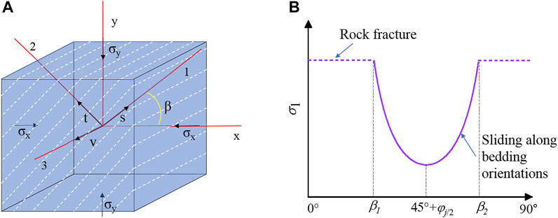
FIGURE 2. (A) Material principal axis and principal stress coordinate system of bedded rock and (B) the strength criterion based on the JPW model.
The shear strength inside the layer is assumed to obey the Coulomb–Navier failure criterion as follows:
Substituting Eq. 2 into Eq. 1, the conditions for shear failure along bedding orientations can be obtained as follows (Zimmerman et al., 2018):
where
The schematic flowchart of preparation of rock specimens with different bedding dip angles is shown in Figure 3. The rock specimens used in the test were taken from the tawny bedded sandstone of Shannan, Qinghai Province, China. The porosity of bedded sandstone is 12.8%, and the dry density is 2.19 g cm−3. According to the International Society of Rock Mechanics standards, the sample was processed into a cylindrical shape with 50 mm diameter and 100 mm height. The length error of all samples was less than 2 mm, and the unevenness of both ends after polishing was within ±0.05 mm. The end face was perpendicular to the axis, the maximum deviation was no more than 0.25°, and the angles between the specimen and the axial direction of the specimen were 0°, 22.5°, 45°, 67.5°, and 90°, respectively, as shown in Figure 3. In order to minimize the influence of the unevenness of the sample on the test results, all samples were taken from different directions on the same rock.
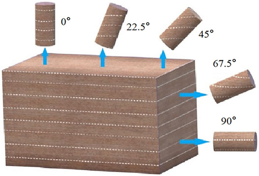
FIGURE 3. Preparation of the rock sample.
Equipment used was the GCTS RTR-1000 rock triaxial test system, as shown in Figure 4. The equipment was controlled by a dynamic and static closed-loop digital electro-hydraulic servo system, which can perform strain or stress control as well as conduct behavior tests after rock failure. The maximum axial load of test equipment is 1,000 kN, and the loading frame stiffness is 1,750 kN/mm. The integrated confining pressure can reach 140 MPa, the pressure resolution is 0.01 MPa, and the liquid volume resolution is 0.01 CC. The rock sample size was up to 75 mm (3 inches). The equipment has an axial and radial linear variable differential transformer measurement, deformation range of ±2.5 mm, and deformation resolution of 0.001 mm.
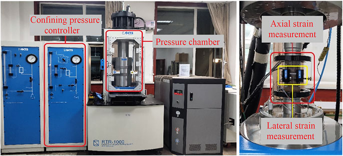
FIGURE 4. Test devices.
The test confining pressure was set to 0, 5, 15, 25, and 40 MPa. The confining pressure was kept constant during each of the four levels of the test, and then the axial force was applied through the displacement control method. The loading rate was 0.01 mm/min, until the specimen was broken. The system automatically recorded the axial and circumferential deformations of the specimen during the test. In order to reduce the influence of the nonuniformity of specimens on the test results, the larger discrete type was removed. The test results were considered valid only when three or more similar results were obtained.
Figure 5 shows the typical stress–strain curves of bedded rocks with different layer dip angles of β = 0°, β = 22.5°, β = 45°, β = 67.5°, and β = 90°, respectively, under different confining pressure of 0 MPa, 5 MPa, 15 MPa, 25 MPa, and 40 MPa. The bedding dip angle of bedded sandstone has a significant impact on its stress–strain relationship. The strength of the bedded sandstone initially decreases with an increase in the bedding dip angle, and reaches a minimum when the bedding dip angle is 67.5°. Subsequently, the strength of bedded sandstone increases with a further increase in the bedding dip angle, reaching a maximum when the bedding dip angle is 90°.
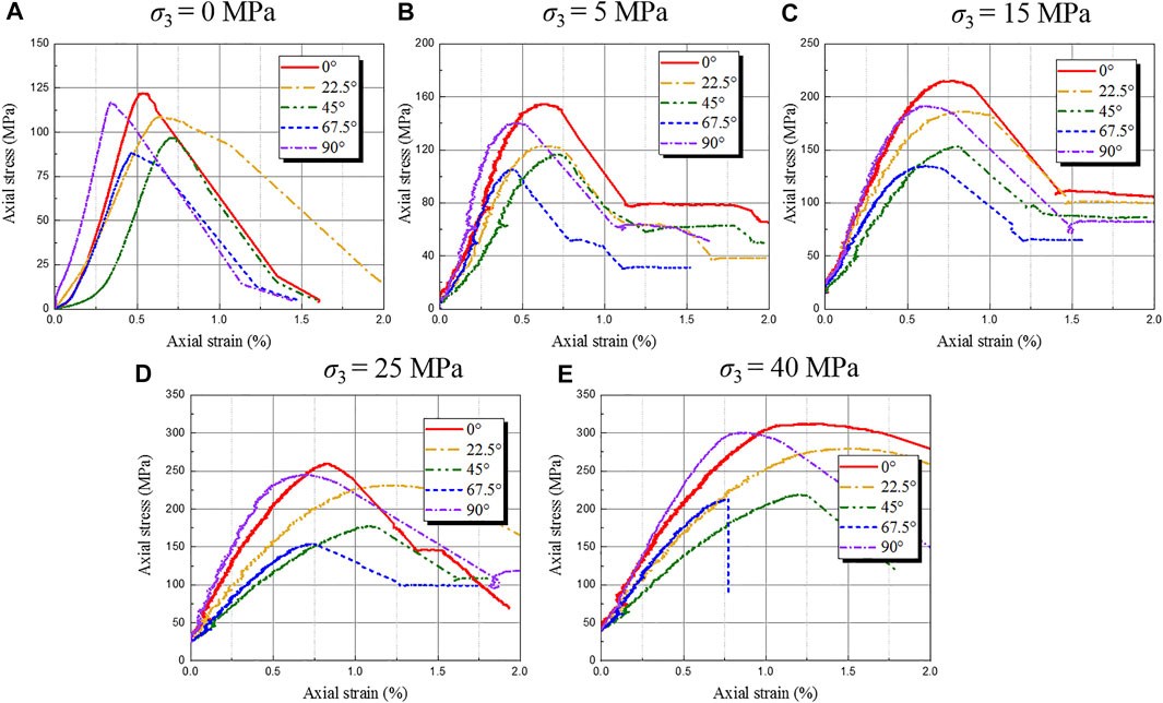
FIGURE 5. Experimental data of compressive strength of bedded rock. (A) σ3 = 0 MPa; (B) σ3 = 5 MPa; (C) σ3 = 15 MPa; (D) σ3 = 25 MPa; (E) σ3 = 40 MPa.
The trend of stress–strain curves of bedded sandstone is consistent with each other. The bedded sandstone experienced, as a whole, four stages of development: the pore and fissure compaction stage; the elastic deformation to the microfracture stable development stage; the stable fracture development stage; and the post-destruction stage. In the rock elastic deformation stage, the elastic modulus of bedded sandstone initially decreased with the increase in the bedding dip angle, and the elastic modulus reached the minimum when the bedding dip angle was 45°. Then, it continuously increased with the increase of the bedding dip angle, and the elastic modulus reached the maximum when the bedding dip angle was 90°. At the beginning of the test, the nonlinear deformation of the curve is due to the gradual compaction of the feeble plane of the bedding and the internal micro-cracks under load. The compression volume deformation of the specimen is also related to the bedding dip angle.
As shown in Figure 6, the confining pressure has an effect on the peak strength of the rock. The triaxial compressive strength σ1 of the rock increases with the increase of the confining pressure σ3, and the increase rate of σ1 corresponding to the rock with different bedding dip angles exhibits significant differences. In addition, the confining pressure also affects the residual strength of the rock. Under uniaxial loading (σ3 = 0 MPa), brittle failure occurs after the rock reaches the maximum strength, and the residual strength is very low; with the increase of the confining pressure, the brittleness of the rock weakens, the plasticity increases, and the residual strength after the peak becomes more obvious.
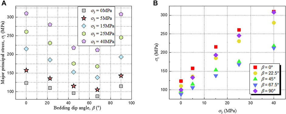
FIGURE 6. Experimental data of compressive strength of bedded rock. (A) Strength of specimens with different bedding dip angles under the same confining pressure; (B) strength of specimens with the same bedding dip angle under different confining pressure.
By comparing the test results of the compressive strength of the bedded sandstone with different confining pressure, it can be found that under the condition of confining pressure σ3 = 0 MPa, the difference value between the compressive strength of the bedded sandstone with bedding dip angles of β = 67.5° and β = 90° is 35.56 MPa. Under the conditions of confining pressure σ3 = 5 MPa, σ3 = 15 MPa, σ3 = 25 MPa, and σ3 = 40 MPa, respectively, the difference values between the compressive strength of the bedded sandstone with bedding dip angles of β = 45° and β = 90° are 51.98, 76.98, 92.74, and 98 Mpa, and compared with σ3 = 0MPa, the difference values of compressive strength increased by 46.2%, 116.5%, 160.8%, and 175.6%, respectively. The strength anisotropy of bedded rock is more significant with the increase of confining pressure.
Bedded sandstone is a transversely isotropic rock, and specimens with different bedding dip angles exhibit different deformation and failure behaviors. The failure modes of bedded sandstone with different bedding dip angles under different confining pressure can be judged by the distribution of rock cracks after the triaxial compression test. It can be seen from Figure 7, with the change of rock bedding dip, the failure mode of bedded sandstone changes accordingly. The failure mode of the bedded sandstone can be divided into three categories as follows: mode I is shear failure, and the rock matrix is cut by the fracture surface. The fracture surface intersects the bedding planes of the rock. Mode II is failed along bedding orientations (weakness planes), and this is a typical failure type of bedded rock. During the loading process, the cracks are formed in a bedding plane locally along the bedding orientations, and then the specimen suffered shear failure along the bedding orientations. Mode III is splitting tension failure. During the loading process, the cracks are formed in multiple bedding planes locally along the bedding orientations, and then the specimen was split along the bedding plane.
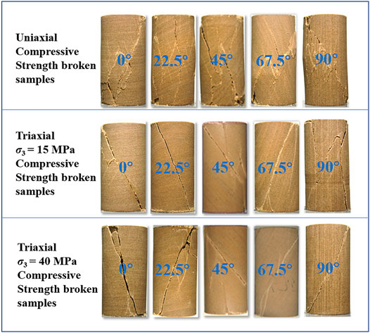
FIGURE 7. Failure characteristic of rock A with different bedding dip angles after the triaxial test.
Under the condition of low confining pressure, the failure mode of bedded sandstone changes from mode I shear failure through the bedding orientations to mode II shear failure along the bedding orientations and finally to mode III splitting tensile failure as the bedding dip angle β increases from 0° to 90°. With the increase of confining pressure, the number of cracks in the rock sample decreases obviously, and the macro-cracks are mainly distributed near the maximum shear stress action surface.
The fractures were scanned when the rock sample is damaged, and the stratification diagram was drawn (see Figure 8). When the bedding dip angle is close to the angle of the maximum shear stress acting plane, the failure mode is the sliding failure in the bedding; on the contrary, the fracture mode is through the bedding plan. The failure mode is closely related to bedding dip angle and confining pressure, and the difference of failure mode also affects the anisotropic characteristics of the aforementioned bedded sandstone.
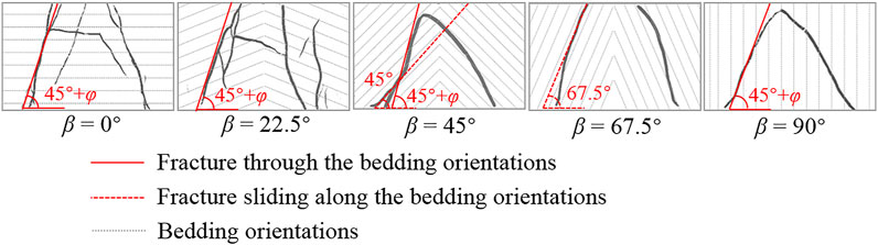
FIGURE 8. Failure characteristic of rock B with different bedding dip angles after the triaxial test.
In the first instance, the original Jaeger’s plane of weakness (JPW) model was used to fit the triaxial experimental data of the bedded sandstone, and then two revised JPW models were proposed as further refinements to the original JPW model and used to fit the experimental data. The JPW model is an empirical strength theory based on the Mohr–Coulomb criterion, which assumes two different fracture mechanisms for bedded rocks. The first is related to the intact rock fracture mechanism, which depends on the cohesion (c0) and the internal friction angle (φ0) of the intact rock. The second is related to the bedding plane fracture mechanism, which depends on the cohesion (cb) and the internal friction angle (φb).
Figure 9 shows the results of fitting according to the JPW model, combined with Figure 7, illustrating that the fracture model of the specimens with β = 45° and β = 67.5° slipping along the bedding planes, while the specimens with β = 0° and β = 90° penetrate fracture through the bedding planes. For the specimen with β = 22.5°, the JPW model does not explain these data well. In future studies, other models will be considered to explore the suitability of the strength criterion under this bedding dip.
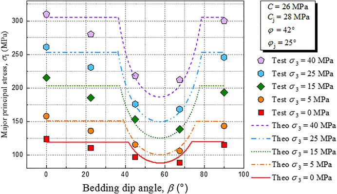
FIGURE 9. Predicted strength curves of the JPW model and experimental values.
The JPW model predicts that bedded rocks exhibit the same peak strength under horizontal bedding dip and vertical bedding dip, which is independent of the bedding dip angle. However, Figure 9 shows a significant difference in peak strength between specimens with β = 0° and those with β = 90°, which has also been confirmed in other authors’ studies (Donath, 1961; Amadei, 1983; Ramamurthy et al., 1988; Duveau and Shao, 1998; Bagheripour et al., 2011; Li et al., 2021). Therefore, the JPW model has a limitation that it cannot accurately represent the mechanical properties that intact rock strength may change continuously with bedding orientation.
In order to overcome the aforementioned shortcoming of the JPW strength criterion for bedded rock, an improved theoretical prediction method of strength anisotropy, called the JPW-MC model, is proposed. The model determines strength parameters of intact rock according to the bedding orientation. In addition, the facture model evolution is also considered the strength of intact rock from fracture through the bedding planes (β = 0°) to splitting tensile failure (β = 90°). This model combines two different failure criteria: for shear failure mode on bedding planes, using the JPW model representation of Eq. 3; for the failure mode on the intact rock, a strength criterion related to the bedding dip is proposed, as shown in Eq. 4.
When determining the parameters corresponding to the intact rock in the JPW-MC criterion, the first step is to determine the strength parameters of the specimens with β = 0° and β = 90° based on the linear strength criterion. As shown in Figures 10A,B, by fitting the relationship between τm = (σ1-σ3)/2 and σm = (σ1+σ3)/2, the cohesion (cb) and the internal friction angle (φb) were determined. Then, the peak strength corresponding to any bedding dip angle β can be calculated according to Eq. 4. Figure 11A shows the results of curve fitting of the JPW-MC criterion. Compared with the JPW criterion, the prediction accuracy of the failure criterion for intact rock is significantly improved.
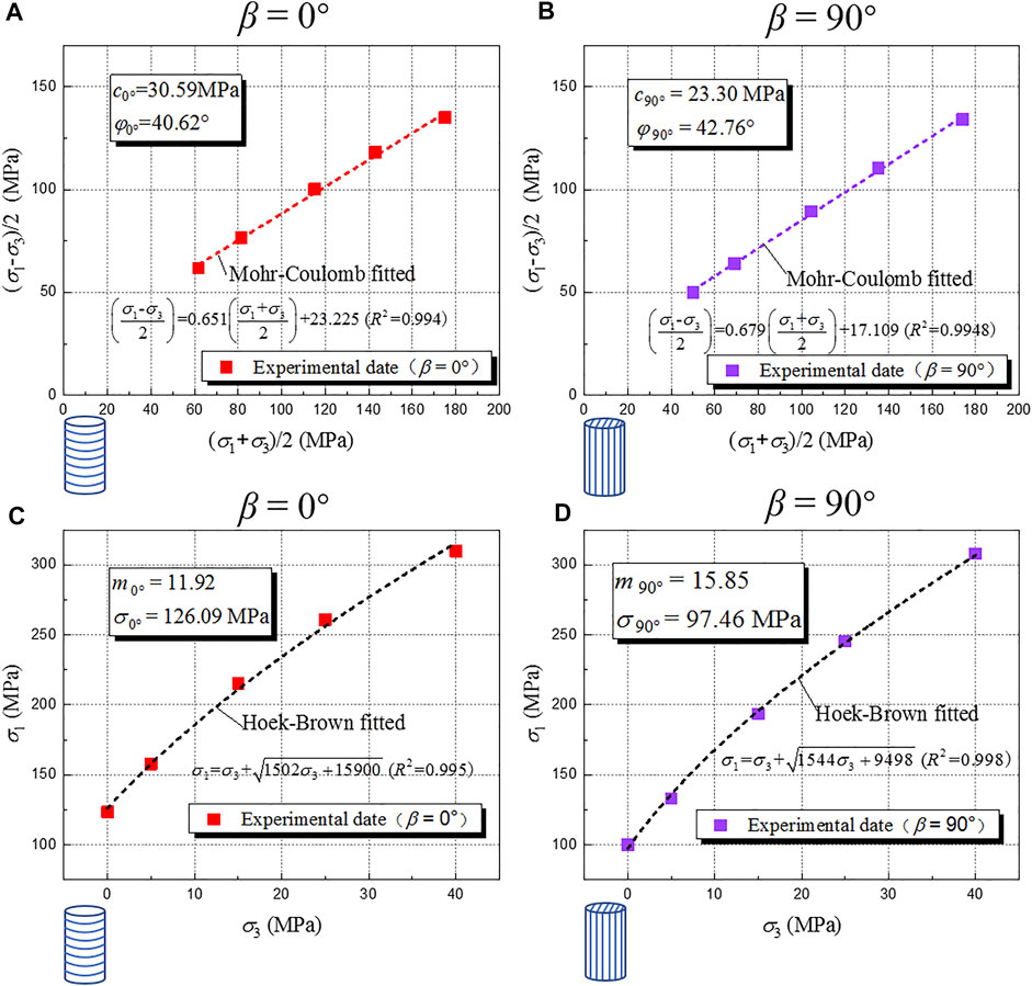
FIGURE 10. Determination of strength parameters of layered sandstone. (A) Mohr–Coulomb strength of bedded sandstone with horizontal bedding dip, (B) Mohr–Coulomb strength of bedded sandstone with vertical bedding dip, (C) Hoek–Brown strength of bedded sandstone with horizontal bedding dip, and (D) Hoek–Brown strength of bedded sandstone with vertical bedding dip.
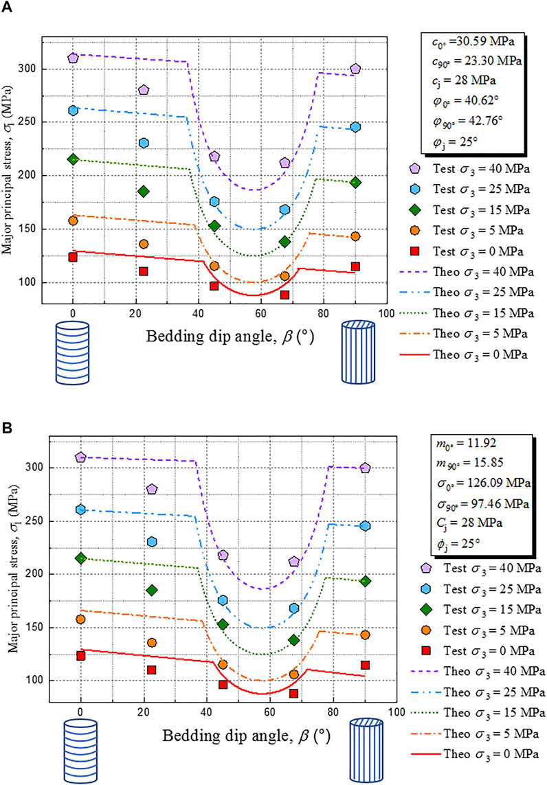
FIGURE 11. (A) Predicted strength curves of the JPW-MC model and experimental values and (B) predicted strength curves of the JPW-HB model and experimental values.
Considering that the rock’s strength envelope is usually nonlinear when the confining pressure changes greatly, an improved theoretical prediction method of strength anisotropy is introduced, called the JPW-HB model. The model is based on the Hoek–Brown nonlinear strength criterion, as shown in Eq. 5.
When determining the parameters corresponding to the intact rock in the JPW-HB criterion, the first is to determine the strength parameters of the specimens with β = 0° and β = 90° based on the linear strength criterion, as shown in Figures 10C,D, through fitting the relationship between σ1 and σ3 and determining the strength parameters m and σci. Then, the peak strength corresponding to any bedding dip angle β can be calculated from Eq. 4. Figure 11B shows the results of curve fitting of the JPW-HB criterion.
There is a significant difference in the strength of the bedded rock between β = 0° and β = 90°. In terms of numerical prediction, compared with the JPW model, the JPW-MC and JPW-HB models, especially the last one, can significantly improve the prediction accuracy of the strength anisotropic behavior of bedded rocks. Since the highest confining pressure of the test conducted in this study is 40 MPa, the advantages of the JPW-HB model are not prominent compared with those of the JPW-MC model. However, when the confining pressure changes greatly in engineering, the strength envelope of the rock is usually a nonlinear curve; at this time, the prediction accuracy of the JPW-HB model based on the nonlinear strength criterion will be more in line with the actual situation.
Different fracture characteristics were observed in triaxial tests on bedded sandstone specimens. The specimens of β in the range of 45°–67.5° failed along bedding orientations (weakness planes), while the specimens with β = 0° and 90° failed through bedding orientations. However, under the condition, it is also observed that the fracture characteristic of the specimens with β = 90° exhibits splitting tensile failure and lower strength than specimens with β = 0°.
The mechanical anisotropy of bedded rock can be directly expressed by the failure mode, which is closely related to not only the bedding dip angle but also the confining pressure. The stress-induced anisotropy of bedded rock caused by confining pressure makes its anisotropic strength more significant with the increase in confining pressure.
The JPW model is proved to be suitable for predicting the anisotropic strength of bedded rock by comparison with experimental data. However, the JPW model has a limitation that it cannot accurately represent the mechanical feature that intact rock strength may change continuously with bedding orientation. The JPW-MC and JPW-HB models proposed in this study improved this shortcoming of the JPW model.
Considering that the rock’s strength envelope is usually nonlinear when the confining pressure changes greatly, the JPW-HB criterion is established on the basis of the Hoek–Brown nonlinear strength criterion. Its prediction accuracy will be more in line with the actual situation in engineering when the confining pressure changes greatly.
The original contributions presented in the study are included in the article/Supplementary Material, further inquiries can be directed to the corresponding authors.
LZ and FN were responsible for the work concept or design; LZ and XJ were responsible for data collection; LZ and ML were responsible for drafting the manuscript; FN and ZW were responsible for making important revisions to the manuscript; JW and TD were responsible for approving the final version of the manuscript for publication.
This research was supported by the Second Tibetan Plateau Scientific Expedition and Research (STEP) Program (Grant No. 2019QZKK0905), the National Key R&D Program of China (Grant No. 2018YFC1505001), the West Light Foundation of Chinese Academy of Sciences (granted to ML), the Program of the State Key Laboratory of Frozen Soil Engineering (Grant No. SKLFSE-ZT-202110), and the Science Technology Research and Development Plan of Qinghai-Tibet Railway Group Corporation (QZ2021-G02).
Authors ZW, JW and TD were employed by the company China Railway Qinghai-Tibet Group Co., Ltd.
The remaining authors declare that the research was conducted in the absence of any commercial or financial relationships that could be construed as a potential conflict of interest.
All claims expressed in this article are solely those of the authors and do not necessarily represent those of their affiliated organizations, or those of the publisher, the editors, and the reviewers. Any product that may be evaluated in this article, or claim that may be made by its manufacturer, is not guaranteed or endorsed by the publisher.
Alejano, L. R., González-Fernández, M. A., Estévez-Ventosa, X., Song, F., Delgado-Martín, J., Muñoz-Ibáñez, A., et al. (2021). Anisotropic Deformability and Strength of Slate from NW-Spain. Int. J. Rock Mech. Mining Sci. 148, 104923. doi:10.1016/j.ijrmms.2021.104923
Amadei, B. (1996). Importance of Anisotropy when Estimating and Measuring In Situ Stresses in Rock. Int. J. Rock Mech. Mining Sci. Geomechanics Abstr. 33 (3), 293–325. doi:10.1016/0148-9062(95)00062-3
Amadei, B. (1983). Rock Anisotropy and the Theory of Stress Measurements. New York, Tokio: Springer-Verlag. doi:10.1007/978-3-642-82040-3
Ambrose, J. (2014). Failure of Anisotropic Shales under Triaxial Stress Conditions. London: Imperial College. Ph.D. Thesis.
Bagheripour, M. H., Rahgozar, R., Pashnesaz, H., and Malekinejad, M. (2011). A Complement to Hoek-Brown Failure Criterion for Strength Prediction in Anisotropic Rock. Geomechanics Eng. 3, 61–81. doi:10.12989/gae.2011.3.1.061
Blenkinsop, T. (2000). Deformation Microstructures and Mechanisms in Minerals and Rocks. Amsterdam, Netherlands: Kluwer Academic Publishers.
Cheng, W., Jin, Y., and Chen, M. (2015). Reactivation Mechanism of Natural Fractures by Hydraulic Fracturing in Naturally Fractured Shale Reservoirs. J. Nat. Gas Sci. Eng. 23, 431–439. doi:10.1016/j.jngse.2015.01.031
Cho, J.-W., Kim, H., Jeon, S., and Min, K.-B. (2012). Deformation and Strength Anisotropy of Asan Gneiss, Boryeong Shale, and Yeoncheon Schist. Int. J. Rock Mech. Mining Sci. 50, 158–169. doi:10.1016/j.ijrmms.2011.12.004
Donath, F. A. (1961). Experimental Study of Shear Failure in Anisotropic Rocks. Geol. Soc. America Bull. 72, 985–989. doi:10.1130/0016-7606(1961)72[985:esosfi]2.0.co;2
Duveau, G., and Shao, J. F. (1998). A Modified Single Plane of Weakness Theory for the Failure of Highly Stratified Rocks. Int. J. Rock Mech. Mining Sci. 35 (6), 807–813. doi:10.1016/s0148-9062(98)00013-8
Duveau, G., Shao, J. F., and Henry, J. P. (1998). Assessment of Some Failure Criteria for Strongly Anisotropic Geomaterials. Mech. Cohes.-Frict. Mater. 3, 1–26. doi:10.1002/(sici)1099-1484(199801)3:1<1::aid-cfm38>3.0.co;2-7
Gonzaga, G. G., Leite, M. H., and Corthesy, R. (2008). Determination of Anisotropic Deformability Parameters from a Single Standard Rock Specimen. Int. J. Rock Mech. Min. Sci. 45, 14201438. doi:10.1016/j.ijrmms.2008.01.014
Hakala, M., Kuula, H., and Hudson, J. A. (2007). Estimating the Transversely Isotropic Elastic Intact Rock Properties for In Situ Stress Measurement Data Reduction: A Case Study of the Olkiluoto Mica Gneiss. Finland. Int. J. Rock Mech. Min. Sci. 44, 1446. doi:10.1016/j.ijrmms.2006.04.003
Hobbs, B. E., Means, W. D., and Williams, P. F. (1976). An Outline of Structural Geology. New York: Wiley, 571–572.
Hoek, E. (1983). Strength of Jointed Rock Masses. Géotechnique 33 (3), 187–223. doi:10.1680/geot.1983.33.3.187
Hu, Z., Shen, J., Wang, Y., Guo, T., Liu, Z., and Gao, X. (2021). Cracking Characteristics and Mechanism of Entrance Section in Asymmetrically-Load Tunnel with Bedded Rock Mass: A Case Study of a Highway Tunnel in Southwest China. Eng. Fail. Anal. 122, 105221. doi:10.1016/j.engfailanal.2021.105221
Jaeger, J. C. (1971). Friction of Rocks and Stability of Rock Slopes. Géotechnique 21 (2), 97–134. doi:10.1680/geot.1971.21.2.97
Li, A., Xu, N., Dai, F., Gu, G., Hu, Z., and Liu, Y. (2018). Stability Analysis and Failure Mechanism of the Steeply Inclined Bedded Rock Masses Surrounding a Large Underground Opening. Tunnelling Underground Space Technology 77, 45–58. doi:10.1016/j.tust.2018.03.023
Li, B., Cui, X., Zou, L., and Cvetkovic, V. (2021). On the Relationship Between Normal Stiffness and Permeability of Rock Fractures. Geophys. Res. Letters 48, e2021GL095593. doi:10.1029/2021GL095593
McLamore, R., and Gray, K. E. (1967). The Mechanical Behavior of Anisotropic Sedimentary Rocks. Trans. Am. Soe. Mech. Eng. Ser. B. 89, 62–73. doi:10.1115/1.3610013
Nasseri, M. H. B., Rao, K. S., and Ramamurthy, T. (2003). Anisotropic Strength and Deformational Behavior of Himalayan Schists. Int. J. Rock Mech. Mining Sci. 40, 3–23. doi:10.1016/s1365-1609(02)00103-x
Ramamurthy, T., Rao, G. V., and Singh, J. (1988). “A Strength Criterion for Anisotropic Rocks,” in Proceedings of the Fifth Australia-Newzeland Conference on Geomechanics, Sydney, August 22–26, 1988, 253–257.
Ramamurthy, T. (1993). Strength and Modulus Responses of Anisotropic Rocks. Oxford: Pergamon Press, 313–329.
Setiawan, N. B., and Zimmerman, R. W. (2018). Wellbore Breakout Prediction in Transversely Isotropic Rocks Using True-Triaxial Failure Criteria. Int. J. Rock Mech. Mining Sci. 112, 313–322. doi:10.1016/j.ijrmms.2018.10.033
Tien, Y. M., and Kuo, M. C. (2001). A Failure Criterion for Transversely Isotropic Rocks. Int. J. Rock Mech. Mining Sci. 38, 399–412. doi:10.1016/s1365-1609(01)00007-7
Winn, K., Wong, L. N. Y., and Alejano, L. R. (2019). Multi-approach Stability Analyses of Large Caverns Excavated in Low-Angled Bedded Sedimentary Rock Masses in Singapore. Eng. Geology. 259, 105164. ISSN 0013-7952. doi:10.1016/j.enggeo.2019.105164
Zhang, X., Liu, W., Jiang, D., Qiao, W., Liu, E., Zhang, N., et al. (2021). Investigation on the Influences of Interlayer Contents on Stability and Usability of Energy Storage Caverns in Bedded Rock Salt. Energy 231, 120968. doi:10.1016/j.energy.2021.120968
Keywords: bedded rock, fracture characteristics, anisotropic, JPW, strength criterion
Citation: Zhang L, Niu F, Liu M, Ju X, Wang Z, Wang J and Dong T (2022) Fracture Characteristics and Anisotropic Strength Criterion of Bedded Sandstone. Front. Earth Sci. 10:879332. doi: 10.3389/feart.2022.879332
Received: 19 February 2022; Accepted: 07 March 2022;
Published: 04 April 2022.
Edited by:
Bo Li, Tongji University, ChinaReviewed by:
Fei Song, Universitat Politecnica de Catalunya, SpainCopyright © 2022 Zhang, Niu, Liu, Ju, Wang, Wang and Dong. This is an open-access article distributed under the terms of the Creative Commons Attribution License (CC BY). The use, distribution or reproduction in other forums is permitted, provided the original author(s) and the copyright owner(s) are credited and that the original publication in this journal is cited, in accordance with accepted academic practice. No use, distribution or reproduction is permitted which does not comply with these terms.
*Correspondence: Fujun Niu, bml1ZnVqdW5AbHpiLmFjLmNu; Minghao Liu, bGl1bWluZ2hhb0BsemIuYWMuY24=
Disclaimer: All claims expressed in this article are solely those of the authors and do not necessarily represent those of their affiliated organizations, or those of the publisher, the editors and the reviewers. Any product that may be evaluated in this article or claim that may be made by its manufacturer is not guaranteed or endorsed by the publisher.
Research integrity at Frontiers
Learn more about the work of our research integrity team to safeguard the quality of each article we publish.