- 1School of Civil Engineering and Architecture, Anhui University of Science and Technology, Huainan, China
- 2School of Civil Engineering and Architecture, East China University of Technology, Nanchang, China
CFMPs (cement and fly ash mixing piles) are used to reinforce fly ash foundation to solve the problem of a large amount of fly ash accumulation in coastal areas. CFMP-fly ash composite foundation is used as the foundation of coastal and coastal engineering. Through the indoor model test, the bearing characteristics and load transfer mechanism of CFMP-fly ash composite foundation under wave load were investigated. The results show that with the increase of wave load, the horizontal resistance of the fly ash stratum increases gradually, the soil resistance moves down, and the level of resistance shows nonlinear characteristics. The pile bending moment, pile displacement, and horizontal resistance of the CFMP composite foundation are concentrated in the upper pile and fly ash stratum, which can improve the ability of the composite foundation to resist horizontal load by improving the physical and mechanical properties of the upper fly ash stratum. Through the calculation of the load–displacement curve, it is found that the measured displacement value is closer to that obtained using the p–y curve method (a method for solving nonlinear lateral resistance of piles). The hysteretic curve area of cyclic loading decreases with the increase of cyclic number. The accumulation of elastoplastic deformation of pile shows that the properties of fly ash gradually change to elastic stage, cyclic loading can reduce the horizontal deformation modulus of composite foundation CFMP caused pile—fly ash system of weakening, in peak load reaches level under the critical state displacement curve showed a trend of the rapid growth of nonlinear, cyclic cumulative failure occurs, and the cyclic load limit state is reached, which affects the service performance of the whole structure.
1 Introduction
As a kind of weak formation, the fly ash stratum has the characteristics of large compressibility, high water permeability, large void ratio, and low shear strength. In actual engineering practice, fly ash foundation can easily cause instability and unevenness. As a result, reinforcement measures are necessary to ensure the safety of the structure built on the fly ash stratum (Zhang, 2011; Tian et al., 2011; Zhang et al., 2011; Du et al., 2021). In recent years, a study on the features of cement–soil mixing pile composite foundation has brought new ideas for the treatment of fly ash foundation (Zotsenko et al., 2015; Luo et al., 2018; Choi and Kang, 2020; Wan et al., 2021; Huang et al., 2021; Guo et al., 2021).
Cement–soil mixed pile composite foundation belongs to the semi-rigid pile composite foundation, which is a widely used foundation treatment technology at home and abroad. It has the advantages of fast construction speed, low project cost, and little influence on the surrounding environment during construction. The cement–soil mixing is used to consolidate the fly ash foundation into cement piles with certain strength, integrity, and water stability with the aim of improving the soil strength (Zhu et al., 2007; Kim et al., 2017; Lu et al., 2019; Sun et al., 2020; Kalita and Anitha Kumari, 2021; Cheng et al., 2021; Seregin, 2022). With the gradual increase of coastal and offshore buildings, the lower foundation not only bears the deadweight load of the upper structure but is also influenced by the horizontal loads, for instance, water flow, wave, and wind during the long-term life service time (Dyson and Randolph, 2001; Motta, 2013; Xu et al., 2020; Wang et al., 2020; Xu et al., 2021; Jin et al., 2021; Huang et al., 2022). Research on the horizontal bearing capacity of the composite foundation has been carried out at home and abroad, and some achievements have been made.
Li et al. (2018) found that DCM-BP had obvious advantages by comparing the horizontal ultimate bearing capacity, pile bending moment, and transverse resistance of DCM-bored pile and conventional bored pile under transverse load. Jeong and Kim (2020) studied the distribution and deformation of loads under transverse loads by means of the p–y curve method using the transverse load transfer method. Through a series of model tests, Mahdi et al. (2021) found that the foundation around the pile moved when the lateral load was applied to the pile, and the pile position moved greatly near the ground level. Richards et al. (2021) studied the bearing characteristics of single pile foundation under cyclic horizontal load, especially pointing out that the pile accumulation displacement rate and secant stiffness change rate gradually decreased with the increase of the load value under cyclic load. Zhang et al. (2019) studied the cumulative deformation response of a single pile under horizontal cyclic load and found that the cumulative displacement of pile top presented two-phase characteristics with the increase of cyclic number. Chen et al. (2018) found out using the model test that the cumulative displacement under cyclic load was larger than that under static load with the same amplitude, and the horizontal displacement relationship was rigid plastic. Chen et al. (2022) accomplished the cyclic detection of the single pile in foundation, and the outcomes indicated that plastic deformation of the soil surrounding the pile would accumulate under the cyclic loading, and the horizontal stiffness of the pile–soil system reduced with increasing number of cycles.
At present, research works on cement–fly ash mixing pile composite foundation mainly focus on its vertical bearing capacity (Zhou SQ. et al., 2020; Zhou S. et al., 2020), while research on the horizontal bearing capacity has been rarely reported. Therefore, research on the bearing characteristics of CFMP composite foundation under horizontal load has important scientific significance and broad application prospects.
In this study, horizontal load tests on CFMP composite foundation were carried out. Both static and cyclic lateral load tests were conducted to study the horizontal load characteristics of composite foundation. The lateral displacement of composite foundation, horizontal resistance coefficient of model pile, bending moment of pile, lateral displacement of pile, horizontal resistance, and pile side soil pressure were analyzed. The applicability of the p–y curve and m methods to calculate the load–displacement curve of CFMP composite foundation was studied and analyzed. The displacement curve, secant stiffness, and pile bending moment of CFMP composite foundation under horizontal cyclic loading were studied and analyzed to explore the influence of CFMP on the horizontal bearing characteristic of fly ash foundation.
2 Materials
2.1 Test Materials
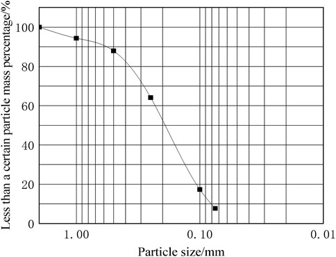
The test model foundation material (fly ash) was taken from a fly ash accumulation site in Huainan City, Anhui Province. In order to eliminate the adverse influence of particle size of test materials on bearing characteristics, according to the conclusion that the influence of foundation bearing characteristics can be ignored when the particle size ratio between model structure and model foundation soil is greater than 23 times, fly ash with particle size less than 2.00 mm was selected for this test. The particle size is divided into <0.075 mm, 0.1–0.075 mm, 0.25–0.1 mm, 0.5–0.25 mm, 1–0.5 mm, and 2–1 mm. Screening tests are carried out on the selected fly ash to obtain fly ash materials with different particle sizes. The gradation of fly ash particles is shown in Figure 1.
2.2 Model Box and Foundation Preparation
In order to meet the distance requirement between the model pile and the inner and bottom walls of the model box, and meet the condition of a semi-infinite filling medium, this test utilizes an acrylic plate model box. The size of the box is 500 × 500 × 750 mm (length × width × height) and wall thickness is 25 mm, and a 10-mm thick steel plate is used for welding reinforcement. At the same time, the model pile size is constrained by the side wall of the model box, and the boundary effect should be considered. Ovesen (1979) discovered that the boundary effect influence could be ignored when the distance between the side wall of the box and the model was larger than 2.82 times of model size. To eliminate the above influence on the test outcomes, the ratio of the diameter of the model pile to the distance between the side wall of the model box and the model pile should be larger than 2.82.
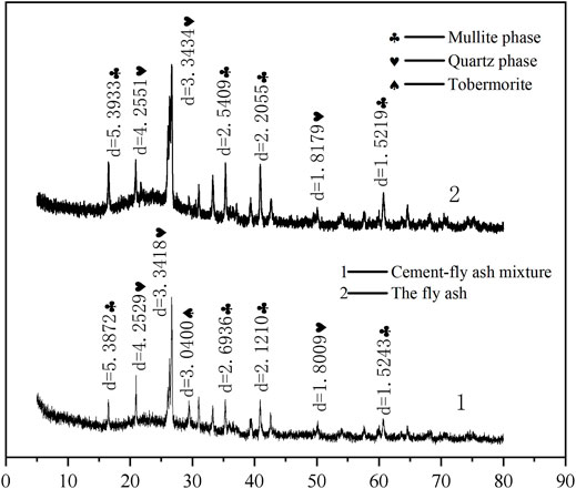
The approach of single compaction times (50 times/layer) and laying layer thickness (10 cm/layer) was used for foundation preparation (Chen et al., 2018). After every 10 cm of fly ash spreading, the fly ash layer was compacted 50 times by a compactor, and then the fly ash layer was pressed by a steel plate and filled to the specified height. In order to make the compactness of the model foundation conform to the requirements of the foundation, the model foundation was subjected to back pressure produced by the self-weight stress of the model foundation. Back pressure load of 1 kg/cm2 was employed on the model foundation surface to accelerate the consolidation of the model foundation (Chen et al., 2018). An X-ray fluorescence analyzer was used to measure the chemical parameters of fly ash. The basic chemical parameters of fly ash are displayed in Table 1. The fundamental physical and mechanical performances of fly ash were measured through indoor tests, and the fundamental physical and mechanical indexes of the fly ash are reflected in Table 2. An X-ray diffractometer is used for diffraction of fly ash, and its diffraction pattern is shown in Figure 2.
2.3 Model Pile
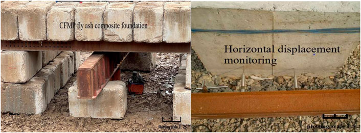
In the model test, the diameter and length of the pile are 40 and 500 mm, respectively, and the aspect ratio is 12.5, which is close to the aspect ratio in the field test condition (the diameter and length of the pile are 1 and 13 m, respectively, and the aspect ratio is 13). The field engineering is shown in Figure 3.
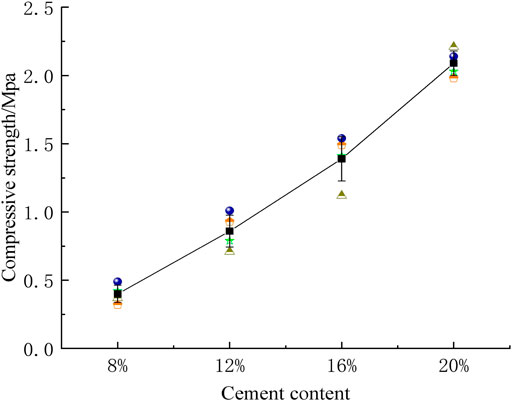
As an important part of the CFMP composite foundation, the change of model pile strength will have a great impact on the bearing capacity of the composite foundation. Therefore, according to the construction technology standard of soil–cement mixing pile (QB-CNCEC J010112-2010), the cement content is generally 7%–20% of the weight of reinforced soil. Four cement mixtures with different proportions (8%, 12%, 16%, and 20%) were selected for the test, and the test block mold (70.7 × 70.7 × 70.7 mm) was used to prepare samples; the module configuration is shown in Table 3. The above four cement and fly ash samples with different proportions were vibrated, compacted, and placed in a curing room for curing. After 28 days, the unconfined compressive strength test was conducted, as shown in Figure 4.
The maximum compressive strength is 2.09 MPa when the content of cement is 20%. This is a 50.36% strength increase compared with 1.39 MPa when the cement content is 16%. Considering the safety of pile foundation design, referring to the construction technology standard of soil–cement mixing pile (7%–20%) and the economic problems of cement cost in field engineering, the proportion of the model pile is 20% cement, 80% fly ash, and 35% water.
After mixing with a ratio of 2:8 cement and fly ash, it was poured into a customized PVC tube with a length of 50 cm, an inner diameter of 4 cm, and a wall thickness of 0.5 cm. It was put into a curing room for 5 days, and then a miniature cutting machine was used to cut the PVC tube. The model pile was removed and cured for 55 days (Zhou SQ. et al., 2020; Zhou S. et al., 2020). The model pile was buried using the embedded method. The fly ash foundation 20 cm below the pile bottom was first filled and compacted; then, the embedded position of the model pile and bearing plate was found using steel ruler measurement. After positioning, the pile body and bearing plate were placed, and the fly ash was filled in time; initial compaction was carried out to ensure that the pile body and bearing plate are vertical. In this way, fly ash was repeatedly filled to complete the burial of the model pile.
2.4 Model Test Design
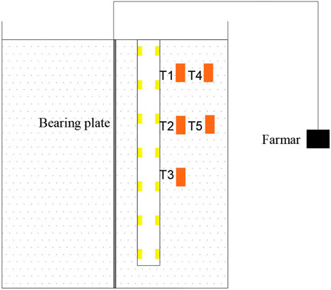
To explore the bearing features of the CFMP composite foundation, several resistance strain gauges were arranged symmetrically along the side of the model pile to measure the strain at various sections of CFMP. Two strain gauges were symmetrically arranged on each section of CFMP, and seven sections were arranged on the pile from top to bottom based on the depth of the pile. The detailed arrangement is reflected in Figure 5. Based on the static load test, the data of the strain gauge were collected by the static strain test system. When measuring the horizontal displacement of the foundation, the important part of the static load test was to choose a dial indicator; the accuracy is 0.01 mm, and the range is 0–20 mm. Two dial indicators were symmetrically installed on the two sides of the bearing plate and kept at the same horizontal line, and the test results were averaged to obtain the horizontal displacement of CFMP composite foundation. In addition, in order to obtain the variation of earth pressure in the model foundation, miniature earth pressure boxes numbered T1–T5 were embedded in the pile side, and the specific layout is shown in Figure 5.
3 Methods
3.1 Test Loading
For model piles, the horizontal static load test should be carried out after setting for 24 h after the completion of embedding. First, the horizontal ultimate bearing capacity of CFMP was determined by a preloading test, and then the loading was carried out in a graded and equal way using the slow loading method, and the unloading amount of each stage was twice the graded load at the loading time. According to the Technical Code for Building Foundation Pile Testing (JGJ 106-2014), after each level of load is applied, at 5, 15, 30, 45, and 60 min to read the displacement value, the next level of load can be applied when the horizontal displacement of foundation under this level of load is not more than 0.1 mm per hour for two consecutive times. When the horizontal displacement is too large to continue loading or the horizontal displacement increases significantly and the deformation rate accelerates rapidly, the loading is terminated. During unloading, the load of each stage should be maintained for 1 h, and the horizontal displacement should be measured at 15, 30, and 60 min. After unloading to zero, the residual displacement should be measured and maintained for no less than 3 h.
Five groups of cyclic load amplitudes were selected according to the horizontal static load test data. The cyclic load test was carried out after the model pile was buried and maintained for 24 h. When the horizontal cyclic load was applied, the design value of cyclic load amplitude was divided into 10 grades. After each load, the horizontal displacement was read after 2 min of dead load; after each load was loaded to the design value, the horizontal displacement was read after 4 min of dead load, and then the unloading began; after each load, the residual displacement was read after 2 min of dead load. This cycle was repeated 30 times to complete the horizontal cyclic loading process.
3.2 Data Processing
Proportional coefficient m of the foundation soil horizontal resistance coefficient is a significant parameter in designing horizontal load. Based on “The Technical Code for Building Pile Foundation” (JGJ 94-2018), for the foundation soil horizontal resistance coefficient, its horizontal deformation coefficient α and proportional coefficient m can be calculated as
where
Based on the strain gauge data, the pile bending moment under various levels of the horizontal load is calculated in Eq. 3, where
From the quadratic integration of the pile bending moment, the pile deflection can be calculated as follows:
Based on the elastic beam theory, the horizontal resistance of pile soil is obtained by differentiating the distributed bending moment twice.
where
where m is the proportional coefficient of horizontal resistance coefficient of foundation soil,
where l is the effective length;
where
4 Results
4.1 Horizontal Static Load Test
After the horizontal static load test of the CFMP-fly ash composite foundation, the data are processed, and the bearing characteristics are analyzed from the ultimate bearing capacity, M value, pile bending moment, pile displacement, horizontal resistance, and earth pressure.
4.1.1 Cement and Fly Ash Mixing Pile Composite Foundation Displacement Gradient Scale
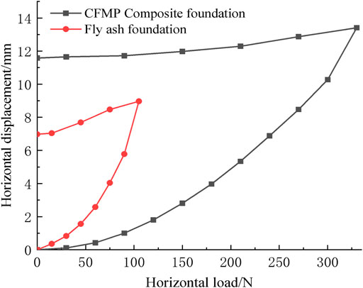
Figure 6 shows the horizontal displacement curve of the CFMP-fly ash composite foundation and fly ash foundation under horizontal load. From Figure 6, it can be found that the horizontal displacement curves of both the fly ash foundation and CFMP-fly ash composite foundation show steep drop characteristics, with obvious inflection points. At the initial stage of horizontal loading (0–90°N), the lateral displacement of the composite foundation increases slowly, and the pile–fly ash system does not show plastic deformation and is in an elastic working state as a whole. The lateral displacement for the composite foundation gradually accumulates with the increasing horizontal load. When the horizontal load reaches 90°N, the growth of lateral displacement accelerates obviously, and the horizontal displacement curve of the composite foundation shows obvious nonlinear characteristics, indicating that the fly ash at the pile side changes from an elastic state to a plastic state. The pile–fly ash system starts to enter the plastic failure stage when the load reaches 300°N, and the horizontal displacement curve appears as an obvious inflection point. In addition, the horizontal displacement curve of the CFMP composite foundation is compared with that of the fly ash foundation under the horizontal load. The lateral displacement of the composite foundation decreases obviously, indicating that the composite foundation can effectively control the lateral displacement of the foundation and can modify the elastic working space of the pile–fly ash system. It can be found that the deformation control ability together with horizontal bearing capacity of the composite foundation is significantly improved compared with the fly ash foundation.
In order to better reflect the correlation between the lateral displacement and horizontal force of composite foundation in the process of the horizontal static load test, the horizontal load–displacement gradient curve is drawn by referring to the determination method of horizontal ultimate load and critical load given in the “Technical Code for Testing Building Foundation Piles” (JGJ 106-2014), as illustrated in Figure 7.
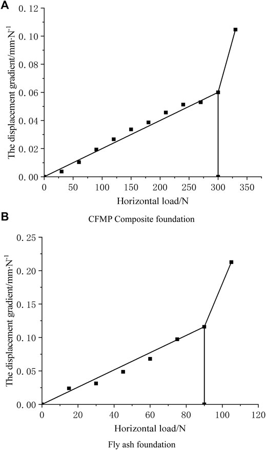
FIGURE 7. Horizontal force–displacement gradient curve of composite foundation under static load. (A) Horizontal force-displacement gradient curve of CFMP composite foundation. (B) Horizontal force-displacement gradient curve of fly ash foundation.
From Figure 7, it can be observed that the horizontal critical load is the horizontal load associated with the first displacement gradient, namely, the horizontal critical load of fly ash foundation, and CFMP-fly ash composite foundation is 90°N and 300°N. The horizontal critical load of CFMP composite foundation is 233% higher than that of fly ash foundation, indicating that composite foundation can evidently improve the horizontal bearing capacity of fly ash foundation and effectively control its lateral deformation.
4.1.2 m Value Curve of Fly Ash Around Piles
Figure 8 shows the relationship curve between the lateral displacement of the foundation and m value. From Figure 8, it can be found that m is not a certain value. The m value and lateral displacement exhibit a nonlinear change correlation. The m value is large when lateral displacement is small, and m is negatively related to lateral displacement. With increasing lateral displacement, m reduces and stabilizes gradually. The correlation between the lateral displacement and m value is similar to that of an inverse proportional curve. In reality, the correlation between the m value and foundation lateral displacement also reveals the nonlinear features of the generation of fly ash to a certain extent. In addition, the m value also shows nonlinear characteristics with the change of horizontal force of the foundation, the m value is high when the load level is small, and the m value gradually reduces with the increasing load level, which may be due to the plastic deformation of fly ash on pile side. Therefore, the lateral displacement of the foundation, soil properties, and horizontal load are the factors affecting the change of the m value, and the m value is mainly influenced via the pile–soil performances and the lateral displacement of the foundation.
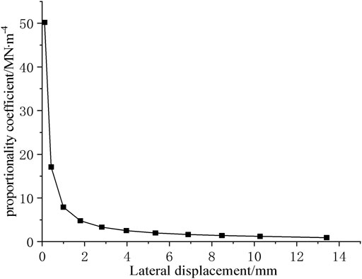
FIGURE 8. Lateral displacement–proportional coefficient curve of composite foundation under static load.
4.1.3 Pile Bending Moment
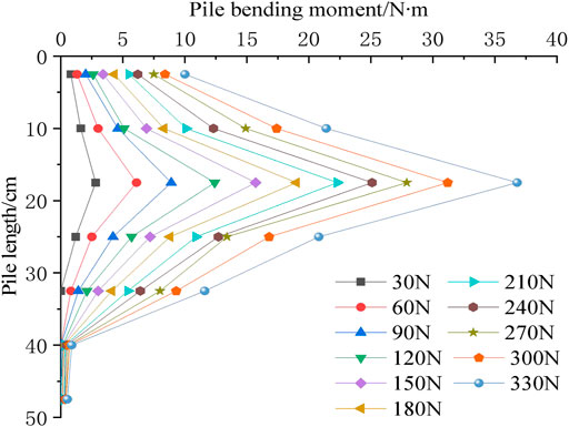
Figure 9 shows the bending moment distribution curve of a single pile under horizontal load at all levels. With increasing pile embedment depth, the pile bending moment first increases and subsequently reduces. Pile bending moment also uniformly increases with increasing horizontal load. The pile bending moment evidently increases when the horizontal load reaches the critical load of 300°N, and the fly ash on the pile side enters an elastic–plastic state. For the CFMP composite foundation, its maximum pile bending moment appears approximately 17.5 cm below the model foundation surface, which is the major influence depth of the pile bending moment. The bending moment of the pile body gradually develops to the deep fly ash stratum with increasing horizontal load. It is believed that the horizontal load is gradually supported by the middle and lower fly ash stratum. In the whole process of the horizontal load test, most of the pile bending moment is distributed between 32.5 cm and above, and tends to 0 in the range of 32.5–47.5 cm. In addition, CFMP composite foundation can effectively enhance the moment resistance ability of the pile foundation by enhancing the physical and mechanical performances of the fly ash formation; hence, the horizontal bearing ability of the pile foundation is significantly improved.
4.1.4 Pile Displacement
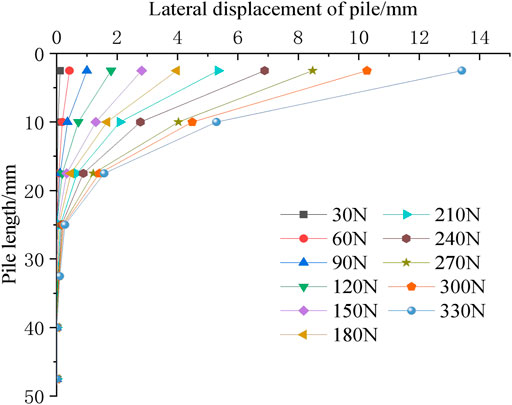
Through Formula 4, pile lateral displacement can be obtained indirectly from the pile bending moment. The pile lateral displacement distribution curve along pile depth under horizontal loads at all levels is shown in Figure 10.
Known from Figure 10, with increasing pile embedment depth, the pile lateral displacement decreases nonlinearly from the ground downward, and most of the displacement concentrates at the pile head. When more than 25 cm depth of the pile lateral displacement is close to zero, the lower lateral displacement of the pile body is influenced by the horizontal force of the foundation, and the bending deformation of the pile bottom is small. The pile deformation near the pile bottom is not high and is approximately vertical. The pile lateral displacement increases synchronously with increasing horizontal load, and increases greatly at the horizontal load of 300°N. With the increase of pile top lateral displacement, the load is gradually transferred to the deep fly ash stratum, and the zero point of pile displacement gradually develops downward, from 17.5 to 32.5 cm. This indicates that the fly ash stratum with a depth of 0–32.5 cm in the CFMP composite foundation is the most affected by horizontal load. In practical engineering, it is very important to improve the engineering properties of fly ash formation in this range to improve the horizontal bearing ability of the CFMP composite foundation.
The lateral displacement control effect of pile top under horizontal critical load is better. When the horizontal critical load is between 0°N and 90°N, the relation between the displacement and horizontal force between the pile and surrounding fly ash is approximately linearly elastic. With increasing horizontal load, the fly ash around the pile enters the stage of plastic deformation. At this time, the relationship between the displacement and horizontal force between the pile and surrounding fly ash is approximately elastic–plastic, which is nonlinear. When the horizontal load reaches the critical load of 300°N, the displacement of the pile increases sharply with the development of plastic deformation of the pile–fly ash system. This indicates that the development rate of pile displacement of the CFMP composite foundation is directly affected by the nonlinear pile section and the plastic development of the pile–fly ash system. Therefore, the greater the load, the less the impact on the limit of the displacement value.
4.1.5 Horizontal Resistance and Soil Pressure of Pile Side
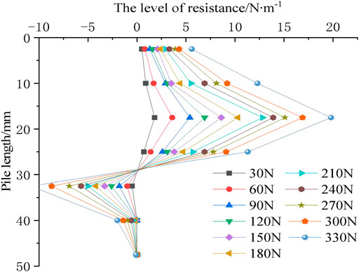
Figure 11 shows the lateral horizontal resistance of the CFMP composite foundation pile under various loads. Based on Figure 11, when the load is constant, the horizontal resistance of the pile side increases first and reaches the maximum value at 17.5 cm of pile body, and then decreases rapidly downward, and there is a certain reverse soil resistance. The soil resistance near the tip of the pile is basically 0. This shows that fly ash from the upper part of pile circumference contributes the most to horizontal resistance. Moreover, along with increasing horizontal load, the horizontal resistance of the fly ash stratum increases gradually, and soil resistance zero position also moves down; this is because as the shallow plastic deformation of fly ash increases gradually, the pile lateral restraint ability declines, the load is passed to the deeper fly ash, and the bending moment of the pile change trend is consistent.
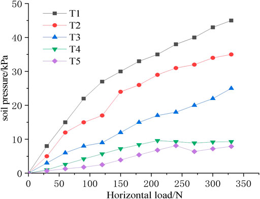
Pile deformation caused by soil pressure on the pile side foundation is the outcome of the interaction of the pile–soil system. The variation law of soil pressure of CFMP composite foundation under horizontal loading is obtained through the micro-earth pressure box T1–T5 embedded in the pile side. Figure 11 shows the relationship curve between pile side earth pressure and horizontal load of miniature earth pressure boxes T1–T5.
On the basis of Figure 12, with increasing horizontal load, the pile side earth pressure gradually increases. When the horizontal load is constant, the soil pressure on the pile side exhibits a downward trend with increasing pile embedment depth (TI, T2, and T3). It can be seen that the soil pressure of the pile side in the shallow part of foundation fly ash is large, and that in the middle and lower parts is relatively small; that is, the physical and mechanical indexes of the fly ash stratum in the shallow part of foundation are the main controlling factors of the horizontal resistance of pile side. The measured earth pressure values of the miniature earth pressure boxes T4 and T5 on the side wall of the model box are all within the range of 5 kPa, and with large horizontal force, some values are less than 10 kPa. It is believed that when the length between the side wall of the model box and model pile is more than 8 D, the influence of horizontal load on the boundary is small or ignored.
4.2 Horizontal Static Load Displacement Calculation
At present, under the action of horizontal load, the theoretical analysis of a single pile at home and abroad is principally classified as the p–y curve method, elastic foundation reaction method, as well as ultimate foundation reaction method (Kobayashi et al., 2009; Hong-jiang et al., 2017; Mao et al., 2018; Wang et al., 2020; Yin et al., 2021; Polishchuk and Shmidt, 2021; Ma et al., 2021; White et al., 2022). Among them, the ultimate foundation reaction method assumes that the pile is rigid and the pile deformation is not considered. As CFMP is a typical semi-rigid pile, which produces a certain degree of pile deformation in the process of horizontal loading, the ultimate foundation reaction method is not applicable. The elastic foundation reaction method is mainly divided into the k method, constant method, double parameter method, c value method, and m method, among which the constant method, k method, and c value method are not discussed here due to their own limitations. In this study, the p–y curve and m methods are employed to study the bearing displacement of the foundation under horizontal load.
Figure 13 shows the measured and calculated load–displacement curves of the model test. In accordance with Figure 13, the calculated value of the m method differs greatly from the measured value, and the displacement value calculated by the p–y curve method is close to the measured value. With increasing horizontal load, the displacement value calculated by the m method is smaller. This may be due to that the soil has entered the plastic stage, while the soil deformation is still calculated by the m method according to the elastic method. The displacement value calculated by the p–y curve is closer to that of the measured value. For the bearing ability of composite foundation, its critical value is 150°N. Under 150°N horizontal load, the measured displacement value is 2.81 mm, while the value calculated by the p–y curve method is 2.67 mm, and the difference value is 4.9%, which can be ignored. Therefore, the p–y curve method can be applied for calculating the bearing ability and load displacement of the CFMP composite foundation.
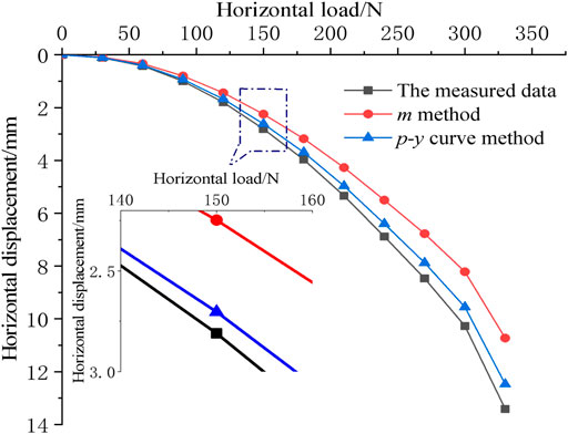
FIGURE 13. Measured and calculated load–displacement curves of model tests under horizontal static load.
4.3 Horizontal Cyclic Load
4.3.1 Hysteresis Curve of Cyclic Loading
By testing the horizontal force and displacement of the CFMP composite foundation, the load–displacement curve under cyclic load is given, as illustrated in Figure 14.
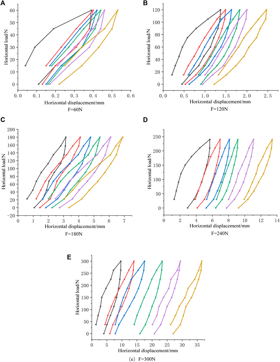
FIGURE 14. Horizontal displacement curve of composite foundation under horizontal cyclic load. (A) Horizontal displacement curve when F = 60N. (B) Horizontal displacement curve when F = 120N. (C) Horizontal displacement curve when F = 180N. (D) Horizontal displacement curve when F = 240N. (E) Horizontal displacement curve when F = 300N.
According to the diagram, the load–displacement curve under circulating load shows a clear hysteresis loop. The horizontal displacement increases with the increase of cycling times. In the first cycle, an obvious nonlinear load–displacement curve can be observed. With the increase of cycles, each cycle load in the process of the linear displacement curve is more and more obvious.
As the number of cycles increases, the whole hysteretic loop gradually shifts to the right and produces cumulative deformation under the unidirectional cyclic loading mode. The area of the hysteretic circle decreases gradually, indicating that the behavior of fly ash around the pile changes from the elastic–plastic stage to the elastic stage.
4.3.2 Stiffness Curve of Cyclic Loading
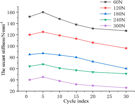
The relationship curve between secant stiffness and cycle times is shown in Figure 15. From Figure 15, it can be observed that the secant stiffness increases within a certain range at the beginning of the cycle. This is because the density of fly ash around the pile gradually increases with increasing cyclic load at the beginning of the cycle. With the accumulation of pile deformation and the increasing number of cycles, fly ash at the pile side gradually transfers to the deep layer. The compactness of deep fly ash decreases under cyclic loading, which results in a decreasing trend in the overall stiffness of the hysteretic loop.
When the amplitude of cyclic load is 60°N, 120°N, 180°N, 240°N, and 300°N, the final secant stiffness decreases by 16%, 18%, 22%, 27%, and 35%, respectively, compared with the initial secant stiffness. The reduction of horizontal secant stiffness of CFMP composite foundation indicates that the horizontal deformation modulus of the fly ash stratum is reduced, which leads to the plastic deformation of fly ash around piles and the weakening of the pile–fly ash system. When the horizontal load is small (F ≤ 120°N), the cyclic load has little disturbance to the soil, and the soil stiffness is basically unchanged. The cyclic cumulative displacement and residual displacement after unloading are relatively small, and the pile–fly ash system is approximately in an elastic state. With the increase of the load (180°N ≤ F ≤ 240°N), the disturbance of the cyclic load to the soil increases, and the stiffness decreases obviously. The cumulative displacement and residual displacement caused by the cyclic load at each stage increase gradually. When the load reaches the horizontal critical load (F = 300°N), the cumulative displacement and residual displacement of soil caused by each cycle increase rapidly, and the increase cannot be stabilized, which is defined as unstable load. CFMP composite foundation under the cyclic load of this amplitude has cyclic cumulative failure and reaches the cyclic load limit state. In addition, under the same load, the cumulative displacement of one-way cyclic load is much larger than that of static load. Therefore, the cyclic effect of the one-way cyclic load has a greater impact on the CFMP composite foundation than that of the static load.
4.3.3 Peak Displacement Curve of Cyclic Loading
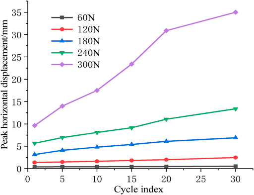
The cumulative peak horizontal displacement of the CFMP composite foundation varies with the number of cyclic loading, as shown in Figure 16. On the basis of Figure 16, the horizontal displacement peak of the CFMP composite foundation increases with increasing load cycle and cyclic load amplitude. When the amplitude of cyclic load is small, its curve is approximately a horizontal straight line. For example, when the cyclic load is 60°N and 120°N, the horizontal displacement peak increases by 0.14 and 1.1 mm, respectively. When the amplitude of cyclic load is large, the horizontal displacement peak-cycle number curve increases steadily and linearly. When the cyclic load amplitude reaches the horizontal critical load (F = 300 N), the horizontal displacement peak curve shows a nonlinear rapid growth trend, which is caused by the failure of the pile–fly ash system when the CFMP composite foundation reaches the cyclic load limit state.
4.3.4 Bending Moment Curve of Pile Under Cyclic Loading
Figures 17, 18 show the variation of pile bending moment distribution and residual bending moment distribution of CFMP composite foundation under horizontal cyclic load with the increase of cyclic number. Based on Figure 18, the increase in the maximum bending moment of the pile body is positively correlated with the number of cycles. This is because cyclic load weakens the stiffness and strength of the fly ash around the pile, resulting in the gap between pile–fly ash and further softening of the pile–fly ash system.
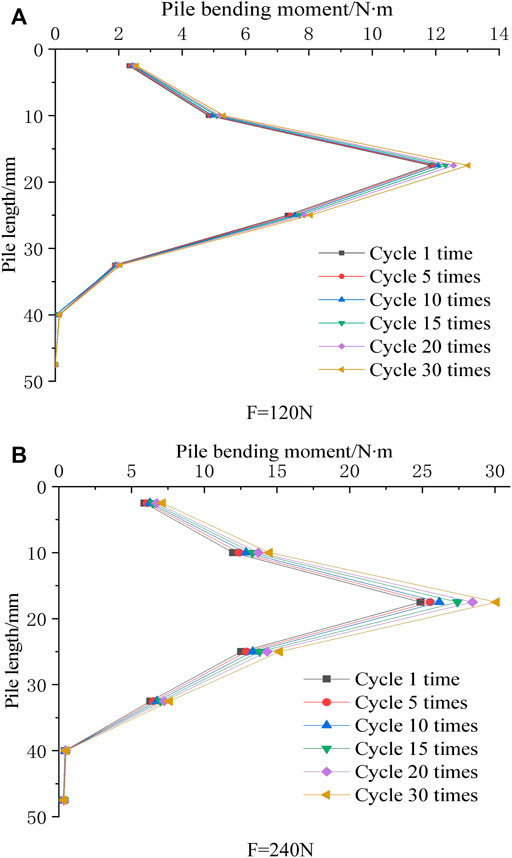
FIGURE 17. Bending moment distribution diagram of composite foundation pile under horizontal cyclic load. (A) Bending moment distribution diagram at F = 120N. (B) Bending moment distribution diagram at F = 240N.
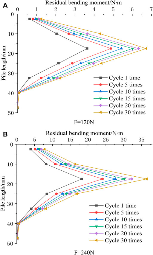
FIGURE 18. Residual bending moment distribution diagram of composite foundation pile under horizontal cyclic load. (A) Distribution diagram of residual bending moment when F = 120N. (B) Distribution diagram of residual bending moment when F = 240N.
When the amplitude of cyclic load is the same, the relative depth of the maximum bending moment together with the maximum residual bending moment in each cycle is constant and does not change with increasing cycle number. When the cyclic load is 120°N and 240°N, the maximum pile bending moment increases by 10% and 21%, respectively, and the maximum residual bending moment changes by 80% and 100%, respectively. It can be seen that the influence of cyclic load on the bending moment is minimal, but its influence on the residual bending moment is much more obvious. This is due to the softening of the fly ash around the pile and pile–fly ash clearance, which reduces the contact between the pile and surrounding fly ash, and the force of the fly ash stratum on the pile during unloading.
5 Discussion
In this study, a horizontal load model test of the CFMP-reinforced fly ash foundation was carried out. The lateral displacement, bending moment of the pile, horizontal resistance of the pile, and soil pressure on the pile side of CFMP composite foundation were studied, and the applicability of the p–y curve method together with the m method to CFMP composite foundation was analyzed. The displacement curve, secant stiffness, and pile bending moment of CFMP composite foundation under horizontal cyclic loading were studied and analyzed. The test results show that the horizontal critical load of CFMP composite foundation was 233% higher than that of fly ash foundation; compared with fly ash foundation treated by dynamic compaction, the bearing capacity increases significantly, indicating that CFMP composite foundation could effectively improve the pile–fly ash-bearing capacity, and had an important influence on the improvement of the horizontal bearing performance of fly ash foundation and enhancing the deformation control ability. Under horizontal load, the maximum bending moment of the CFMP composite foundation was located between the upper and middle parts of the pile, and such depth is the major depth affecting the bending moment of the pile. The pile displacement of CFMP decreased linearly with increasing horizontal load, and its displacement mainly occurred at the top of the pile. With increasing lateral displacement of the pile top, the zero point of displacement gradually developed toward the middle of the pile. Therefore, the fly ash formation in the middle and upper parts of the CFMP composite foundation under horizontal load was the most strongly affected, and the strength of fly ash in this area should be enhanced in practical engineering. CFMP strengthened the fly ash around the pile, and the lateral binding of the pile was enhanced. Soil resistance gradually developed with the increase of horizontal lateral displacement. At the late loading stage, the fly ash stratum began to have plastic failure and the load was transferred downward. Therefore, CFMP improved the physical and mechanical performances and strength of fly ash around piles, which further increases the pile side soil pressure and improves the ability of the composite foundation to resist the horizontal load. Compared with the traditional concrete pile, CFMP shows better horizontal bearing characteristics and reduces the pile bending moment to a certain extent. The pile displacement degree of CFMP is smaller than that of the traditional concrete pile and has better stability.
The load–displacement curve obtained by using the conventional p–y curve method and m method was basically consistent with the shape and trend of the measured curve of the model pile. The calculation result of the m method was small, while that of the p–y curve method was closer to the measured value, exhibiting that the p–y curve method could be employed for calculating the bearing capacity and horizontal displacement curve of the CFMP composite foundation.
The area of the hysteretic curve circle of cyclic loading gradually decreased with increasing cycle number, indicating that the behavior of fly ash around piles changed from elastic–plastic to elastic. The cumulative horizontal displacement increased linearly until the cyclic load reached the critical load value, and the pile–fly ash system was destroyed when it reached the critical load. The horizontal secant stiffness increased first and then decreased, and the earlier cyclic load increased the compactness of fly ash. With increasing cycle number, the fly ash resistance around the pile transferred from the shallow layer to the deep layer, and the fly ash compactness at the shallow layer decreased. When the cyclic load amplitude reached the critical load, it entered the cyclic load limit state, and the service performance of the CFMP composite foundation was affected. Compared with the current research results on fly ash foundation, CFMP composite foundation has obvious bearing capacity advantages, which can greatly improve the horizontal bearing capacity of fly ash foundation, meet the engineering needs, and has a good engineering application prospect.
6 Conclusion
1) CFMP composite foundation has a significant effect on improving the horizontal bearing capacity and enhancing the deformation control ability of the fly ash foundation. Under the action of horizontal load, pile deformation and foundation bearing horizontal load are concentrated on the pile body, which can improve the bearing capacity of the composite foundation by enhancing the engineering properties of the upper fly ash foundation.
2) Through the calculation of the load–displacement curve of the CFMP-fly ash composite foundation, it can be seen that the p–y curve method is more close to the measured value. In engineering applications, the p–y curve method can be used to predict the displacement of composite foundation, so as to better formulate engineering plans.
3) Under the action of horizontal cyclic load, the displacement rate and area of the hysteretic curve show a negative correlation trend with the increase in the number of cyclic loads. The fly ash resistance of the pile body transfers to the deep layer, and when the cyclic load value reaches the critical load, it enters the ultimate state under load, thus affecting the service performance of the CFMP composite foundation; therefore, the bearing capacity of composite foundation should be designed according to the critical load in engineering design.
Data Availability Statement
The original contributions presented in the study are included in the article/Supplementary Material; further inquiries can be directed to the corresponding author.
Author Contributions
HZ: writing—original draft preparation and writing—review and editing; SZ: conceptualization and methodology; RZ: validation and formal analysis; DL: supervision. All authors have read and agreed to the published version of the manuscript.
Funding
This research was funded by the National Natural Science Foundation of China (42061011 and 41977236) and the Graduate Innovation Fund project of Anhui University of Science and Technology in 2021 (2021CX 2038).
Conflict of Interest
The authors declare that the research was conducted in the absence of any commercial or financial relationships that could be construed as a potential conflict of interest.
Publisher’s Note
All claims expressed in this article are solely those of the authors and do not necessarily represent those of their affiliated organizations, or those of the publisher, the editors, and the reviewers. Any product that may be evaluated in this article, or claim that may be made by its manufacturer, is not guaranteed or endorsed by the publisher.
Acknowledgments
The authors sincerely thank the School of Civil Engineering and Architecture, State Key Laboratory of Mining Response and Disaster Prevention and Control in Deep Coal Mine in Anhui University of Science and Technology for providing the experiment conditions.
References
Chen, L., Zhou, J., Duan, J., Wang, X., and Xie, Y. (2022). Wave Loads on High-Rise Pile Cap Structures and Mitigation Approach. Ocean. Eng. 243, 110189. doi:10.1016/j.oceaneng.2021.110189
Chen, Y. W., Huang, M. S., and Lou, C. Y. (2018). Model Tests and Analyses of Caisson Foundation Based on Gravel Cushion under Cyclic Lateral loads(Article). Chin. J. Geotechnical Eng. 40 (9), 1619–1626. doi:10.11779/CJGE201809007
Cheng, X., Chen, J., Cai, X., Zhang, X., Gong, L., and Gu, C. (2021). Dynamic Response of CFG and Cement-Soil Pile Composite Foundation in the Operation Stage. Geomechanics Eng. 26 (4), 385–399. doi:10.12989/gae.2021.26.4.385
Choi, Y., and Kang, G. (2020). A Study on the Behavior of Piled Abutment Subjected to Lateral Soil Movement of Soft Ground Improved by Deep Cement Mixing Method. J. Eng. Geol. 30 (2), 131–145. doi:10.9720/kseg.2020.2.131
Du, F.-L., Lu, S.-F., Liu, J.-B., Cao, B.-Y., Zhao, X.-G., Mao, A.-Q., et al. (2021). Field Test of Composite Ground Improved by Different Methods in Red Soil Areas of China. Proc. Institution Civ. Eng. - Geotechnical Eng. 174 (3), 315–330. doi:10.1680/jgeen.19.00269
Dyson, G. J., and Randolph, M. F. C. (2001). Monotonic Lateral Loading of Piles in Calcareous Sand. J. Geotechnical Geoenvironmental Eng. 127. doi:10.1061/(asce)1090-0241(2001)127:4(346)
Guo, Z., Shi, Y., Huang, F., Fan, X., and Huang, J. (2021). Landslide Susceptibility Zonation Method Based on C5.0 Decision Tree and K-Means Cluster Algorithms to Improve the Efficiency of Risk Management. Geosci. Front. 12 (12), 101249. doi:10.1016/j.gsf.2021.101249
Hong-jiang, L., Tong, L. Y., Song-yu, L., Gu, M. F., and Zhan-qiu, L. (2017). Displacement Standards for Lateral Capacity of Rigid Pile and Flexible Pile in Soft Soil foundation(Article). Rock Soil Mech. 38 (9), 2676–2682. doi:10.16285/j.rsm.2017.09.027
Huang, F., Tao, S., Chang, Z., Huang, J., Fan, X., Jiang, S.-H., et al. (2021). Efficient and Automatic Extraction of Slope Units Based on Multi-Scale Segmentation Method for Landslide Assessments. Landslides 18, 3715–3731. doi:10.1007/s10346-021-01756-9
Huang, F., Yan, J., Fan, X., Yao, C., Huang, J., Chen, W., et al. (2022). Uncertainty Pattern in Landslide Susceptibility Prediction Modelling: Effects of Different Landslide Boundaries and Spatial Shape Expressions. Geosci. Front. 13, 101317. doi:10.1016/j.gsf.2021.101317
Jeong, S., and Kim, Y. (2020). Analysis for Laterally Loaded Offshore Piles in Marine Clay. Geotech. Eng. 51 (2), 166–171.
Jin, X., Chen, J., and Liao, C. (2021). Wave Flume Simulation Experiment on Influence of Wave Load on Bearing Capacity of Monopile. Shanghai Jiaot. Daxue xuebao 55 (4), 365–371. doi:10.16183/j.cnki.jsjtu.2019.268
Kalita, D. M., and Anitha Kumari, S. D. (2021). Effect of Composite Pile Foundation System on the Behavior of Soft Ground. Lect. Notes Civ. Eng. 120, 109–119. doi:10.1007/978-981-33-4005-3_9
Kim, S., Whang, S.-W., Kim, S., and Hyung, W. G. (2017). Application of Extended End Composite Pile Design in Pile Foundation Work. Proc. Institution Civ. Eng. - Geotechnical Eng. 170 (5), 455–465. doi:10.1680/jgeen.16.00043
Kobayashi, T., Ochiai, H., Suyama, Y., Aoki, S., Yasufuku, N., and Omine, K. (2009). Bearing Capacity of Shallow Foundations in A Low Gravity Environment. Soils Found. 49 (1), 115–134. doi:10.3208/sandf.49.115
Li, H., Liu, S., and Tong, L. (2018). Field Investigation of the Performance of Composite Foundations Reinforced by DCM-Bored Piles under Lateral Loads. Constr. Build. Mater. 170, 690–697. doi:10.1016/j.conbuildmat.2018.03.112
Lu, X., Mengen, S., and Wang, P. (2019). Numerical Simulation of the Composite Foundation of Cement Soil Mixing Piles Using FLAC3D. Clust. Comput. 22, 7965–7974. doi:10.1007/s10586-017-1544-6
Luo, J., Liu, X., Huang, H., Mi, D., and Che, D. (2018). Mechanism Analysis and Application of Cement-Soil Mixing Pile in Soft Roadbed Treatment. Revue des Compos. des matériaux avancés 28 (2), 161–172. doi:10.3166/rcma.28.161-172
Ma, B., Li, Z., Cai, K., Liu, M., Zhao, M., Chen, B., et al. (2021). Pile-Soil Stress Ratio and Settlement of Composite Foundation Bidirectionally Reinforced by Piles and Geosynthetics under Embankment Load. Adv. Civ. Eng. 2021, 1–10. doi:10.1155/2021/5575878
Mahdi, T. K., Al-Neami, M. A., and Rahil, F. H. (2021). An Experimental Study on Laterally Loaded Winged Pile in Sandy Soil. IOP Conf. Ser. Earth Environ. Sci. 856, 012051. doi:10.1088/1755-1315/856/1/012051
Mao, J. Q., Xu, J., and Yang, L. (2018). An Improved Method for Stabilising Pile by Using M-Method Model to the Whole pile(Article)[J]. Rock Soil Mech. 39 (4), 1197–1202. doi:10.16285/j.rsm.2016.0993
Motta, E. (2013). Lateral Deflection of Horizontally Loaded Rigid Piles in Elastoplastic Medium. J. Geotech. Geoenviron. Eng. 139 (3), 501–506. doi:10.1061/(ASCE)GT.1943-5606.0000771
Ovesen, N. K. (1979). The Use of Physical Models in Design: the Scaling Law relationships//Proceedings of the 7th European Conference on Soil Mechanics and Foundation Engineering. Brighton 4, 318–323.
Polishchuk, A. I., and Shmidt, O. A. (2021). Method for Calculating the Settlement of Circular Pile Foundations of a Reservoir. Soil Mech. Found. Eng. 58 (5), 347–352. doi:10.1007/s11204-021-09750-y
Richards, I. A., Bransby, M. F., Byrne, B. W., Gaudin, C., and Houlsby, G. T. (2021). Effect of Stress Level on Response of Model Monopile to Cyclic Lateral Loading in Sand. J. Geotechnical Geoenvironmental Eng. 147 (3), 1–16. doi:10.1061/(ASCE)GT.1943-5606.0002447
Seregin, N. (2022). Parametric Model of Cement Soil. Lect. Notes Civ. Eng. 180, 481–491. doi:10.1007/978-3-030-83917-8_43
Sun, Y., Cheng, J., Li, Y., Chen, Q., Zhang, W., and Shao, G. (2020). Model Test of the Combined Subgrade Treatment by Hydraulic Sand Fills and Soil-Cement Mixing Piles. Bull. Eng. Geol. Environ. 79 (6), 2907–2918. doi:10.1007/s10064-020-01735-9
Tian, J., Xia, B. S., Wang, J. D., and Wei, T. (2011). Studies on Geology of the Backfilling Fly Ash and the Foundation Treatments. Amr 243-249, 3182–3188. doi:10.4028/www.scientific.net/amr.243-249.3182
Wan, Y., Song, L., Zhu, Z., and Peng, Y. (2021). Research on Construction Quality Monitoring and Evaluating Technology of Soil-Cement Mixing Piles. Soil Mech. Found. Eng. 58 (1), 85–91. doi:10.1007/s11204-021-09710-6
Wang, J.-P., Su, J.-B., Wu, F., Zhang, Z., and Lv, Y. (2021). Lateral Dynamic Load Tests of Offshore Piles Based Using the M-Method. Ocean. Eng. 220, 108413. doi:10.1016/j.oceaneng.2020.108413
Watanabe, K., Arakawa, M., Mizumoto, M., and Enomoto, H. (2020). Study on Evaluation of Bearing Capacity for Soil-Cement Mixing Wall Using Permanent Pile. J. Soc. Mat. Sci. Jpn. 69 (1), 15–20. doi:10.2472/jsms.69.15
White, D. J., Doherty, J. P., Guevara, M., and Watson, P. G. (2022). A Cyclic P-Y Model for the Whole-Life Response of Piles in Soft Clay. Comput. Geotechnics 141, 104519. doi:10.1016/j.compgeo.2021.104519
Xu, D.-s., Xu, X.-y., Li, W., and Fatahi, B. (2020). Field Experiments on Laterally Loaded Piles for an Offshore Wind Farm. Mar. Struct. 69, 102684. doi:10.1016/j.marstruc.2019.102684
Xu, X., Zhang, Z., Yao, W., and Zhao, Z. (2021). Dynamic Stability Analysis of Pile Foundation under Wave Load. Int. J. Geomechanics 21 (4), 1–15. doi:10.1061/(ASCE)GM.1943-5622.0001968
Yin, K., Li, L., and Di Filippo, E. (2021). A Numerical Investigation to Determine the P-Y Curves of Laterally Loaded Piles. Mathematics 9, 2783. doi:10.3390/math9212783
Zhang, J. W., Zhu, M. J., and Zhang, L. W. (2011). Research on the Disposal for Fly Ash Weak Foundation by Spraying Powder Pile. Amm 71-78, 3785–3788. doi:10.4028/www.scientific.net/amm.71-78.3785
Zhang, X., Huang, M., and Hu, Z. (2019). Model Tests on Cumulative Deformation Characteristics of a Single Pile Subjected to Lateral Cyclic Loading in sand(Article. Rock Soil Mech. 40 (3), 933–941. doi:10.16285/j.rsm.2017.2081
Zhou, S. Q., Zhang, Y. F., Zhou, D. W., Wang, W., Ke, Z., and Sudipta, H. (2020a). Fly Ash Foundation Reinforced by Cement-Soil Mixing Piles. Dyna - Ing. E Ind. 95 (2), 1–7. doi:10.6036/9364
Zhou, S., Zhang, Y., Zhou, D., Wang, W., Li, D., and Ke, Z. (2020b). Experimental Study on Mechanical Properties of Fly Ash Stabilized with Cement. Adv. Civ. Eng. 2020, 1–11. doi:10.1155/2020/6410246
Zhu, Z., Xi, P., Zhang, B., Zhou, L., and Zhu, Z. (2007). Monitoring and Analysis of Composite Foundation Reinforced by T-Shaped Bidirectional Soil-Cement Deep Mixing Pile under Embankment Loads. Chin. J. Rock Mech. Eng. 26, 4530–4537.
Keywords: fly ash foundation, model test, wave load, cyclic load, bearing performance
Citation: Zhang H, Zhou S, Wang R and Li D (2022) Dynamic Response of Cement–Fly Ash Mixed Pile Composite Foundation Under Wave Load. Front. Earth Sci. 10:857907. doi: 10.3389/feart.2022.857907
Received: 19 January 2022; Accepted: 19 April 2022;
Published: 01 June 2022.
Edited by:
Faming Huang, Nanchang University, ChinaReviewed by:
Parveen Sihag, Chandigarh University, IndiaCamilo Higuera, National University of Colombia, Colombia
Mohamed Mostafa Hassan Mostafa, University of Kwazulu-Natal, South Africa
Chethan B. A., Government Engineering College Hassan, India
Copyright © 2022 Zhang, Zhou, Wang and Li. This is an open-access article distributed under the terms of the Creative Commons Attribution License (CC BY). The use, distribution or reproduction in other forums is permitted, provided the original author(s) and the copyright owner(s) are credited and that the original publication in this journal is cited, in accordance with accepted academic practice. No use, distribution or reproduction is permitted which does not comply with these terms.
*Correspondence: Haojin Zhang, emhqY3NsQDE2My5jb20=
 Haojin Zhang
 Shengquan Zhou1