- 1School of Civil and Transportation Engineering, Ningbo University of Technology, Ningbo, China
- 2School of Architectural Engineering, Chang’an University, Xi’an, China
- 3School of Civil Engineering, Chongqing University, Chongqing, China
- 4Guangxi Key Laboratory of Disaster Prevention and Engineering Safety, Guangxi University, Nanning, China
- 5Ningbo Engineering Prospecting Institute Co., Ltd., Ningbo, China
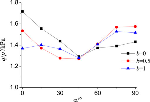
To investigate the strength and deformation characteristics of Q2 remodeled loess, soil samples from the Lishi area in Shanxi Province were adopted to examine the effects arising from the principal stress axis direction angle α and the medium principal stress ratio b on the shear and non-coaxial properties of remodeled loess based on the hollow cylindrical torsional shear system. As indicated by this study, when b was constant, the generalized shear stress ratio decreased with the increase in α at 0°–45°, while achieving the minimum value when α = 45°; α increased again with the increase in the principal stress axis direction angle at 45°–90°. When α was 0–45°, the generalized shear stress ratio tended to decrease with the increase in the intermediate principal stress ratio b. When α was 60°–90°, the shear strength ratios at different intermediate principal stress ratios were obtained as: strength at b = 0.5 > strength at b = 1 > strength at b = 0. Moreover, after the degree of strength volatility of this remodeled loess was defined to determine its breaking strain standard, it was found through a comparative analysis that when the generalized shear strain of this remodeled loess was 6.5%, the strength of this remodeled loess was over 90%. Thus, this study suggested the use of its generalized shear strain of 6.5% as its breaking strain standard. In addition, when α was at 0–45°, the direction angle of strain increment increased with the increase in the direction angle of the principal stress axis and reached the peak at 45°. When α was at 60°–90°, the direction angle of strain increment decreased with the increase in the direction angle of the principal stress axis, i.e., the non-coaxial characteristics of the remolded loess first increased, then decreased, and further tended to be coaxial.
Introduction
In general, the stress state of soil in traffic engineering has changed in the direction of the principal stress axis. Due to the direction of the principal stress axis, the actual stress state of the soil can be simulated realistically. Before the 1980s, impacted by the immaturity of science and technology, there had been no experimental equipment capable of changing the magnitude and direction of soil principal stress simultaneously, and the experimental research on principal stress rotation had been rare. With the continuous development and improvement of test instruments (e.g., the hollow cylindrical torsion shear instrument with the principal stress axis continuously rotating) (Dong et al., 2017b; Xu et al., 2017; Shen et al., 2006; Yao et al., 1996), scholars worldwide have extensively investigated the shear properties and deformation characteristics of soils under complex stress, and they have achieved certain results. As reported by Miura et al. (1986), with the increase in the principal stress axis direction angle, the maximum shear strain of loose sand increased continuously, and the dense sand showed first the appearance of dilatancy, followed by shear shrinkage. Researchers also conducted corresponding experiments on the strength of geotechnical materials (Fan et al., 2019; Fan et al., 2020; Jiang et al., 2016; Liu et al., 2020(a); Liu et al., 2020(b); Wang et al., 2022(a); Wang et al., 2022(b); Wang et al., 2020; Wang et al., 2021; Zhou et al., 2022; Xu et al., 2022). Symes et al. (1985) suggested that the rotation of the principal stress axis had a non-negligible effect on the stress-strain characteristics of saturated sand. Subsequently, according to Nakata et al. (1998) and Vaid et al. (1990), the principal stress axis direction angle could have an important effect on the deformation of sand through the shear test of the principal stress axis rotation.
In addition, impacted by the differences in the mechanical properties of the soil along each direction, the non-coaxial properties of the reshaped loess should be investigated in depth. Hu et al. (2018) performed hollow cylindrical torsional shear tests on pulverized fine sand under principal stress axial rotation. They found that the medium principal stress coefficient significantly affected axial, shear, and body strains. Wang et al. (2018) performed a clay drainage torsional shear test and suggested that the middle principal stress ratio and the principal stress axis direction angle significantly affected the non-coaxial effect of clay. Weng et al. (2018) performed torsional shear experiments with two different stress paths and reported that the shear strength of reshaped loess was significantly correlated with the middle principal stress coefficient b and the principal stress axis direction angle α. When the principal stress direction angle changed cyclically, there would be a stress-strain hysteresis phenomenon (Chen et al., 2015; Dong et al., 2017a; Feng et al., 2018). also performed directional shear experiments on remodeled loess in different principal stress axis directions. They suggested that the principal stress rotation significantly affected the strain increment of remodeled loess.
In general, directional shear tests and principal stress rotation tests have been extensively performed, whereas there have been rare research results on the shear characteristics and non-coaxial characteristics of reshaped loess based on different middle principal stress coefficients and principal stress axis directions. Accordingly, in this study, the hollow cylindrical torsional shear system was adopted for experiments on the loess in the Lishi area under standard consolidation drainage conditions, and the effects arising from different principal stress axis directions and medium principal stress coefficients on the directional shear characteristics and non-directional shear characteristics of Q2 remodeled loess were investigated, as well as the effect arising from coaxial properties.
Test Program
Testing Apparatus and Soil Sample
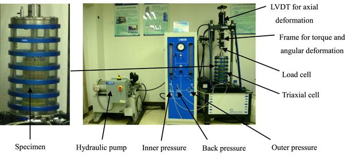
The hollow cylindrical torsion shear instrument produced by GCTS Company in the United States was employed as the test instrument adopts, as presented in Figure 1.
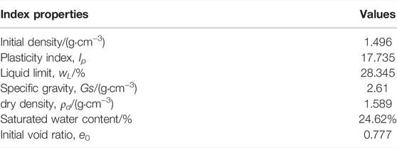
The soil samples applied in the test were taken from the Lishi area of Shanxi Province. The soil samples were light yellow, with a considerable number of pores and scattered characteristic. Table 1 lists the basic physical parameters of the soil samples.
To clarify the mineral composition content of loess in the Lishi area, an X-ray diffractometer was employed to measure its basic mineral composition content. Table 2 lists the test results.
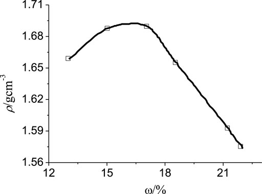
To make the state of reshaped sample closer to the state of engineering soil, the optimal moisture content of the soil sample should be controlled, and the sample should be compacted. In accordance with the standard compaction test results under different moisture content conditions (Figure 2), it was concluded that the optimal moisture content of the Q2 loess was 16.4%, and the maximum dry density was 1.69 g/cm3.
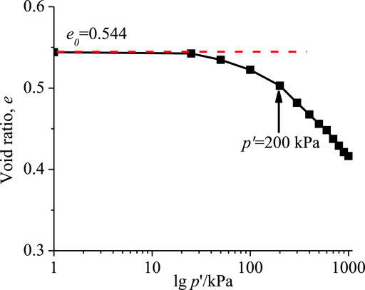
A certain pre-pressure should be applied to the soil sample to ensure that the remodeled soil sample maintains a normal consolidation state during the shearing process (Figure 3). The soil maintained normal consolidation during the shearing process, so the effective consolidation pressure applied in the test was 200 kPa.
Preparation of soil samples: The optimal moisture content and the maximum dry density were measured using the standard compaction test as 16.4% and 1.69 g/cm3, respectively. A certain amount of loose soil was taken, dried in an oven for over 8 h, and then crushed. After the 5 mm Geo-sieve was completed, the soil sample was mixed under the sieve, and the mixed soil sample was placed into a plastic bag and sealed for over 2 days, so the loess was evenly wetted. The required wet soil mass was calculated according to the sample size and the maximum dry density, the wet soil was divided into 10 layers, and the compaction height of each layer of soil samples was controlled to be the same. Next, the soil samples were uniformly pressed.
Soil sample saturation consolidation: the prepared remodeled soil sample was placed into the saturator. Subsequently, the saturator was put into the vacuum saturation cylinder for air extraction. The pipe clamp was slowly opened, and clean water was poured into the cylinder till the liquid level exceeded the soil sample saturator. Afterward, the water injection ended, and the sample was kept in the water for over 10 h to ensure that the sample was saturated with water. Next, the water in the pumping cylinder was discharged to obtain a saturated reshaped soil sample.
Test Procedure
The parameters applied in the test are written below:
where σz denotes the axial stress of the specimen; σθ represents the circumferential stress; τzθ expresses the torsional shear stress; σr is the radial stress; α represents the angle between the stress direction and the axial direction; σ1 denotes the maximum principal stress; σ2 is the middle principal stress;σ3 is the minimum principal stress.
Where b denotes the middle principal stress coefficient; p represents the average principal stress of the unit body; p′ is the average effective stress of the unit body; q is the generalized shear stress of the unit body; η denotes the generalized effective deviatoric stress ratio.
Where γ denotes the generalized shear strain; εv, ε1, ε2, and ε3 represent the bulk strain, the maximum principal strain, the medium principal strain, and the minimum principal strain, respectively.
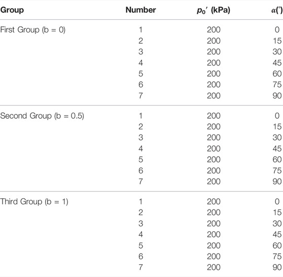
After soil consolidation was completed, the direction angle of the principal stress axis and the middle principal stress coefficient were adjusted, based on the adjustment time of 1h, and the shear rate was set to 0.2 kPa/min. A total of 21 remodeling soil samples were examined and fell into three groups in accordance with different middle-principal stress ratios. The direction angles of the principal stress axis were 0°, 15°, 30°, 45°, 60°, 75°, and 90°, respectively, and the middle principal stress coefficient b corresponding to the respective deflection angle was 0, 0.5, and 1, respectively. Table 3 lists the specific test plan.
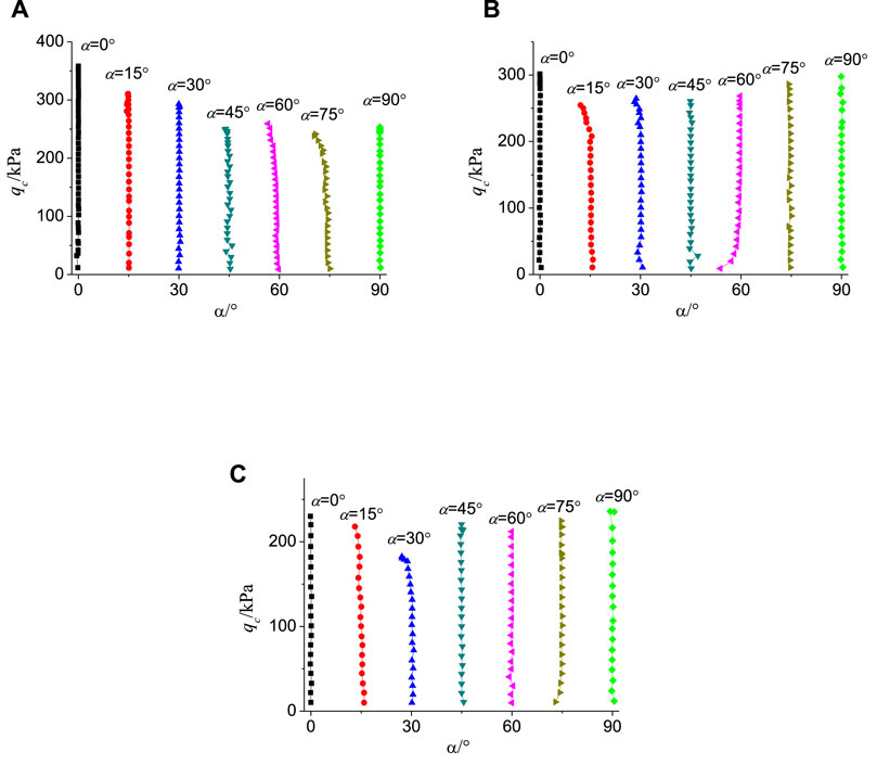
To perform the fixed shear test at different principal stress axis direction angles, the direction angle α of the principal stress axis and the middle principal stress coefficient b should be controlled, respectively. Figure 4 presents the shear stress path measured by the test. The deviatoric stress is expressed as (qc = σ1-σ3).
According to Figure 4, the stress path of the sample fluctuated significantly during the initial loading process. At the middle stage of loading, the test instrument could more effectively control the loading path and realize fixed shearing with different middle principal stress ratios and different principal stress axis directions.
Test Results and Analysis
Influence of Principal Stress Orientation
Figure 5 presents the generalized stress ratio-strain curves of different principal stress axis orientation angles based on different middle principal stress coefficients. As indicated by the figure, at the initial stage of shearing, the shear strain of the reshaped loess increased rapidly when the generalized shear stress ratio rapidly increased. During the early shearing, since the reshaping of the loess had high strength, the speed of the increase of strength ratio was higher than the growth of the shear strain rate. With the further increase in the shear stress, the curve inflection point began to appear, and the loess began to reshape. In the late shearing, the remolded sample strain grew quickly, and its strength ratio almost changed to the level of growth.
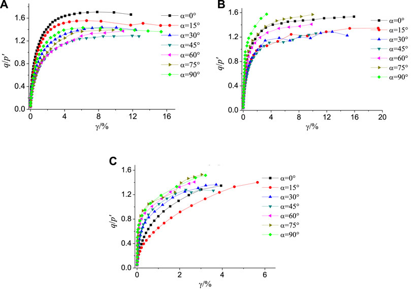
FIGURE 5. Curves of generalized shear stress ratio-strain diagram at different principal stress direction angles: (A) b = 0; (B) b = 0.5; (C) b = 1
By comparing and analyzing the generalized shear stress ratio-strain development curves of different principal stress axis direction angles α under the same middle principal stress coefficient b, it was found that when the middle principal stress coefficients b = 0 and b = 0.5, the reshaped loess exhibited strain hardening characteristics and the strain at failure could reach nearly 15%; when the principal stress coefficient b = 1, the remodeled loess exhibited a strain-softening effect and the strain at failure was relatively small, approximately 3–5%. Moreover, the direction angle of the principal stress axis significantly affected the q/p'-γ relationship of the specimen: when α was between 0° and 45°, the stress ratio tended to decrease with the increase in the direction angle of the principal stress axis, and at 45°. When α was at 45°–90°, the stress ratio increased again with the increase in the direction angle of the principal stress axis.
Influence of Middle Principal Stress
Figure 6 presents the q/p'-γ change curves at different middle-principal stress ratios under the same principal stress axis direction angle. As revealed by the above figure, the change curve of the strength ratio of the remodeled loess followed a consistent change rule in different principal stress axis directions. For the growth rate of strain, with the further increase in the shear stress, the curve began to show an inflection point, and the remodeled loess began to yield. At the later stage of shearing, the strain of the remodeled soil increased rapidly, and the strength ratio changed almost horizontally.
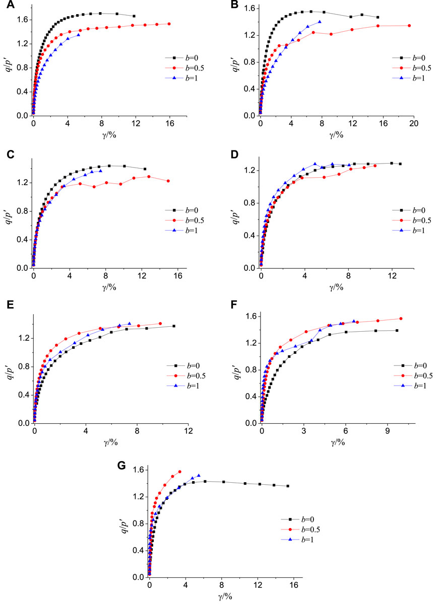
FIGURE 6. Curves of generalized shear stress ratio-strain diagram at different intermediate stress parameters: (A) α = 0°; (B) α = 15°; (C) α = 30°; (D) α = 45°; (E) α = 60°; (F) α = 75°; (G) α = 90°
By comparing and analyzing the generalized shear stress ratio-strain development curves of different middle principal stress coefficients at the same principal stress axis direction angle, it was found that the effect of b increased with the increase in generalized shear strain. When the direction angle α of the principal stress axis was 0–45°, the generalized shear stress ratio tended to decrease with the increase in the middle principal stress coefficient b. When α was at 60°–90°, the strength ratios at the three stress ratios are expressed as shear strength at b = 0.5 > shear strength at b = 1 > shear strength at b = 0. When the middle principal stress coefficient b changed from 0 to 1, the stress state of the reshaped soil sample varied from the state of triaxial compression to the state of triaxial tension. The compressive capacity of the soil sample was higher than the tensile capacity, so its plastic dilatation capacity tended to decrease in the shearing process.
Shear Failure of Remolded Loess
Indicated by existing research, for soil failure with a complex stress path, the generalized shear strain value allowed under certain conditions has been generally employed as the failure criterion. Guo et al. (2003) investigated Fujian standard sand using a geotechnical static-dynamic hydraulic triaxial-torsional multifunctional shear instrument. They suggested the generalized shear strain of 5% as its failure criterion. As reported by Wang et al. (1996), when the generalized shear strain was 6.5%, it should serve as the failure standard of the soil material for the core wall of the waterfall ditch. Chen et al. (2005) studied the original and remodeled soft clay in Xiaoshan using a multi-functional triaxial tester, and they took the turning point with the dynamic stress-strain curve increasing significantly as its failure point. Zheng (2011) presented the strength development ratio of clay under complex stress paths by defining the strength development degree. They found that the generalized shear strain of 8% should serve as the failure standard for remodeling soft clay. Shen et al. (1996) conducted a conventional dynamic torsional shear test and dynamic principal stress axis rotation test based on a dynamic torsional shear instrument with two-directional vibration, and they further confirmed the generalized shear strain of 10% as the failure criterion for dynamic cyclic rotation of sandy soil.
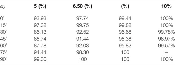
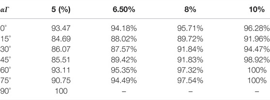
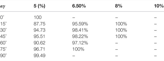
As revealed by the above research, the degree of strength development could intuitively reflect the degree of development of the material’s strength. Accordingly, for the Q2 remodeled loess in the test of this study, the strength development degree of the remodeled loess is also written as S = q/qf, where q denotes the generalized shear stress during the loading process of the sample, and qf is the failure peak generalized shear stress of the sample. The directional shear test results at different principal stress axis direction angles based on different middle principal stress ratios were adopted to achieve the strength development results with the generalized shear strain suggested above, as listed in Tables 4–T6.
According to the above table, for the strength volatility of this remodeled loess obtained under different Intermediate principal stress ratios, the relative strength reduction of the remodeled loess can reach more than 90% when the generalized shear strain is 6.5%. Thus, for this remodeled loess, it would be recommended that its generalized shear strain of 6.5% should serve as its breaking strain standard.
Based on the failure strain standard determined by the strength volatility, the generalized stress ratios of different principal stress axis direction angles at different middle principal stress ratios are expressed on the same coordinate, as presented in Figure 7. According to the above figure, when the middle principal stress coefficient was definite, the generalized peak shear stress ratio first decreased and then increased with the increase in the principal stress axis direction angle, and the generalized peak shear stress was the smallest when α = 45°.
Non-Coaxial Properties of Remodeled Loess
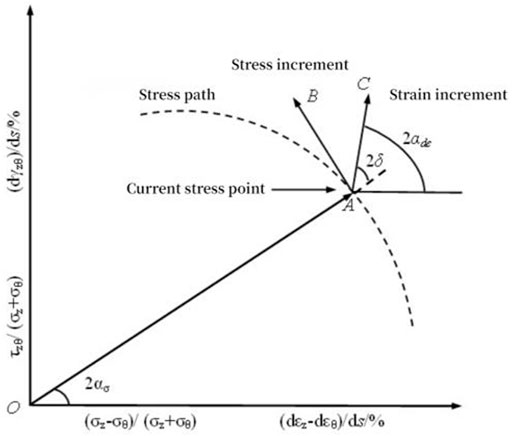
Figure 8 presents a schematic diagram of the non-coaxial properties of the soil, where: ασ denotes the principal stress axis direction angle, αdε represents the principal strain increment direction angle, δ expresses the non-coaxial angle, the stress increment is AB (ds), and the strain increment is AC, the origin of the coordinate system is O.
Since the non-coaxial property of soil has been found as the property that the direction of plastic strain increment is not co-axial with the direction of stress, it is difficult to calculate the elastic deformation of soil accurately from the total strain. Thus, the total strain increment direction was used instead of the plastic strain increment in this study.
The calculation formula is written as:
Where dτzθ denotes the increment of the shear stress; dσz represents the increment of the axial stress; dσθ expresses the increment of the circumferential stress; dγzθ is the increment of the shear strain; dεz denotes axial strain increment of the specimen during the shearing process; dεθ represents circumferential strain increment of the specimen during the shearing process.
Figure 9 illustrates the variation characteristics of the directional shear non-coaxial strain increment of the remodeled loess. As revealed by the figure, the anisotropy of the soil sample was insignificant at the initial angle, whereas the stress-strain of the soil sample still showed significant non-coaxial characteristics. Moreover, the non-coaxial characteristic increased and then decreased with the increase in the principal stress axis direction angle, and tended to be co-axial. From Figures 1–3, the medium principal stress coefficient had a significant effect on each strain component, and the non-coaxial characteristic was more obvious with the increase in the medium principal stress ratio.
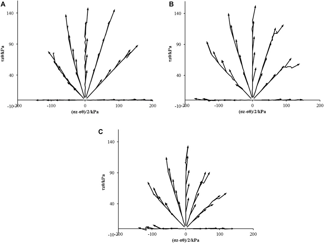
FIGURE 9. The non-coaxial characteristics of the remolded loess in the deviatoric plane: (A) b = 0; (B) b = 0.5; (C) b = 1
Anisotropy is usually considered to be the root cause of non-coaxial (Desrues J et al., 2002). Figure 10 shows the change of the direction angle of the strain increment under different middle principal stresses. As indicated by the above figure, the effect of the direction angle of the different principal stress axis led to the anisotropic soil stiffness, thus making the non-coaxial phenomenon significant. When α was at 45°, αdε reached a peak. When α was at 0° and 90°, αdε reached a trough. In general, the direction angle of strain increment first increased and then decreased with the increase in generalized stress, i.e., the non-coaxial characteristics of the reshaped loess first increased and then decreased.
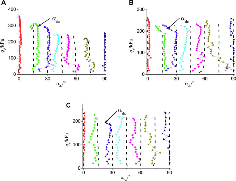
FIGURE 10. Variation of strain increment angle of remolded loess at different medium principal stress ratios: (A) b = 0; (B) b = 0.5; (C) b = 1
Conclusion
(1) When the principal stress ratio b was the same, the generalized shear stress ratio of α tended to decrease at 0°–45°, and the generalized shear stress was the smallest when α = 45°, and the generalized shear stress tended to increase when α was 45°–90°. The trend revealed the strength anisotropy of the soil. Moreover, with the increase in the middle principal stress ratio, the generalized tangent modulus reached the maximum value when b = 0.5. On the whole, the generalized shear modulus of the remodeled loess showed a trend of first increasing and then decreasing with the increase in the middle principal stress ratio.
(2) When the direction angle α of the principal stress axis esd 0–45°, the generalized shear stress ratio tended to decrease with the increase in the middle principal stress coefficient b; when α was 60°–90°, the strength ratios under the three stress ratios indicated that: shear strength at b = 0.5 > shear strength at b = 1 > shear strength at b = 0. During the growth and change of the middle principal stress coefficient b from 0 to 1, the stress state of the reshaped soil sample varied from the state of triaxial compression to the state of triaxial tension. The compressive capacity of the soil sample was higher than the tensile capacity, so its plastic dilatation capacity gradually decreased in the shearing process.
(3) As indicated by the comparative analysis, when the generalized shear strain of the remodeled loess was 6.5%, its strength development reached over 90%. Accordingly, it is recommended to employ the generalized shear strain of 6.5% as the failure strain standard for the Q2 remodeled loess.
(4) When α is 0–45°, the direction angle of the strain increment increases with the increase in the direction angle of the principal stress axis, and reaches a peak at 45°, and when α is 60°–90°, the direction angle of the strain increment increases. It decreases with the increase in the direction angle of the principal stress axis, that is, with the increase in the direction angle of the principal stress axis, the non-coaxial characteristic first increases and then decreases, and gradually tends to be coaxial. With the increase in the generalized stress, the direction angle of the strain increment of the remodeled loess develops first in a positive direction and then in a negative direction under different middle-principal stress ratios, that is, the non-coaxial characteristic first increases and then decreases.
The work presented in this paper was sponsored by the Supported by Systematic Project of Key Laboratory of New Technology for Construction of Cities in Mountain Area (No. LNTCCMA-20200104), the Systematic Project of Guangxi Key Laboratory of Disaster Prevention and Structural Safety (No. 2019ZDK005), the Initial Scientific Research Fund of Young Teachers in Ningbo University of Technology (2140011540012), the Ningbo Public Welfare Science and Technology Planning Project (No. 2019C50012). These financial supports are gratefully acknowledged.
Data Availability Statement
The original contributions presented in the study are included in the article/Supplementary Material, further inquiries can be directed to the corresponding author.
Author Contributions
SW and PZ conduct the tests, ZG, and ZZ analyzed the data; BC and CS drow the graphics.
Funding
The work presented in this paper was sponsored by the Supported by Systematic Project of Key Laboratory of New Technology for Construction of Cities in Mountain Area (No. LNTCCMA-20200104), the Systematic Project of Guangxi Key Laboratory of Disaster Prevention and Structural Safety (No. 2019ZDK005), the Initial Scientific Research Fund of Young Teachers in Ningbo University of Technology (2140011540012), the Ningbo Public Welfare Science and Technology Planning Project (No. 2019C50012). These financial supports are gratefully acknowledged.
Conflict of Interest
Author QS was employed by the company Ningbo Engineering Prospecting Institute Co., Ltd.
The remaining authors declare that the research was conducted in the absence of any commercial or financial relationships that could be construed as a potential conflict of interest.
Publisher’s Note
All claims expressed in this article are solely those of the authors and do not necessarily represent those of their affiliated organizations, or those of the publisher, the editors, and the reviewers. Any product that may be evaluated in this article, or claim that may be made by its manufacturer, is not guaranteed or endorsed by the publisher.
Abbreviations
po, the outer confining pressure; σz, vertical stress; τzθ, shear stress; Ip, plasticity index; wL, liquid limit; Gs, specific gravity, /(g·cm−3); ρd, dry density; ω, water content; e0, initial void ratio; η, cyclic shear stress ratio; σz, cyclic deviatoric stress magnitude; τzθ, cyclic shear stress magnitude; p0', mean effective consolidation stress.
References
Chen, W., Zhang, W. Y., and Chang, L. J. (2015). Experimental Study on Anisotropy of Compacted Loess Under Directional Shear Stress Path. Chin. J. Rock Mech. Eng. 34 (S2), 4320. doi:10.13722/j.cnki.jrme.2014.0911
Chen, Y. P., Huang, B., and Chen, Y. M. (2005). Deformation and Strength Characteristics of Structural Soft Clay Under Cyclic Loading. J. geotechnical Eng. 24 (9), 937. doi:10.1007/s11769-005-0030-x
Desrues, J., and Chambon, R. (2002). Shear Band Analysis and Shear Moduli Calibration. Int. J. Sol. Structures 39 (13/14), 3757–3776. doi:10.1016/s0020-7683(02)00177-4
Dong, T., Zheng, Y. R., and Kong, L. (2017a). Nonlinear Elastic Model of Soil Considering Principal Stress Direction. Rock Soil Mech. 38 (5), 1373. doi:10.16285/j.rsm.2017.05.019
Dong, T., Zheng, Y. R., Kong, L., and Zhe, M. (2017b). Control and Realization of Generalized Stress Path in Torsion Shear Test of Hollow cylinder. Chin. J. Geotechnical Eng. 39 (S1), 106. doi:10.11779/CJGE2017S1021
Fan, J., Jiang, D., Liu, W., Wu, F., Chen, J., and Daemen, J. (2019). Discontinuous Fatigue of Salt Rock with Low-Stress Intervals. Int. J. Rock Mech. Mining Sci. 115 (3), 77–86. doi:10.1016/j.ijrmms.2019.01.013
Fan, J., Liu, W., Jiang, D., Chen, J., Tiedeu, W. N., and Daemen, J. J. K. (2020). Time Interval Effect in Triaxial Discontinuous Cyclic Compression Tests and Simulations for the Residual Stress in Rock Salt. Rock Mech. Rock Eng. 53, 4061–4076. doi:10.1007/s00603-020-02150-y
Feng, Y. Z., Zhang, W. Y., and Ma, Y. X. (2018). Deformation of Remolded Loess Under Principal Stress Axis Rotation Considering the Influence of Deviator Stress Ratio. J. Disaster Prev. Mitigation Eng. 38 (03), 535. doi:10.13409/j.cnki.jdpme.2018.03.018
Guo, L. (2013). Experimental Study on Static and Dynamic Characteristics of Saturated Soft clay under Complex Stress Path. Hangzhou, China: Zhejiang University. (in Chinese).
Hu, P., Wei, C., and Yang, L. Q. (2018). Research on Deformation Characteristics of Sand Under Reciprocating Rotation of Principal Stress Axis. Chin. J. Underground Space Eng. 14 (4), 955
Jiang, D., Fan, J., Chen, J., Li, L., and Cui, Y. (2016). A Mechanism of Fatigue in Salt under Discontinuous Cycle Loading. Int. J. Rock Mech. Mining Sci. 86 (7), 255–260. doi:10.1016/j.ijrmms.2016.05.004
Liu, W., Zhang, X., Fan, J., Zuo, J., Zhang, Z., and Chen, J. (2020b). Study on the Mechanical Properties of Man-Made Salt Rock Samples with Impurities. J. Nat. Gas Sci. Eng. 84, 103683. doi:10.1016/j.jngse.2020.103683
Liu, W., Zhang, Z., Fan, J., Jiang, D., Li, Z., and Chen, J. (2020a). Research on Gas Leakage and Collapse in the Cavern Roof of Underground Natural Gas Storage in Thinly Bedded Salt Rocks. J. Energ. Storage 31, 101669. doi:10.1016/j.est.2020.101669
Miura, K., Miura, S., and Toki, S. (1986). Deformation Behavior of Anisotropic Dense Sand under Principal Stress Axes Rotation. Soils and Foundations 26 (1), 36–52. doi:10.3208/sandf1972.26.36
Nakata, Y., Hyodo, M., Murata, H., and Yasufuku, N. (1998). Flow Deformation of Sands Subjected to Principal Stress Rotation. Soils and Foundations 38 (2), 115–128. doi:10.3208/sandf.38.2_115
Shen, R. F., Wang, H. J., and Zhou, J. X. (1996). Dynamic Strength of Sand under Continuous Rotation of Dynamic Principal Stress Axis. Acta Hydrodynamics 2020 (1), 27
Shen, Y., Zhou, J., and Gong, X. N. (2006). Hollow Cylinder Apparatus to Simulate Circulating Rotating Stress Path of Principal Stress Axis Under Constant Confining Pressure. Chin. J. Geotechnical Eng. 28 (3), 281.
Symes, M. J., Shibuya, S., Hight, D. W., and Gens, A. (1985). Liquefaction with Cyclic Principal Stress Rotation. Proc. 11th Int. Conf. Soil Mech. Found. Eng. 4, 1919.
Vaid, Y. P., Sayao, A., Hou, E., and Negussey, D. (1990). Generalized Stress-path-dependent Soil Behaviour with a New Hollow cylinder Torsional Apparatus. Can. Geotech. J. 27, 601–616. doi:10.1139/t90-075
Wang, H. J., Ma, Q. G., Zhou, J. X., and Zhou, K. J. (1996). Study on Dynamic Characteristics of Soil under Complex Stress State. J. Hydraulic Eng. 2021 (04), 576.
Wang, J., Wang, X., Zhang, Q., Song, Z., and Zhang, Y. (2021). Dynamic Prediction Model for Surface Settlement of Horizontal Salt Rock Energy Storage. Energy 235, 121421. doi:10.1016/j.energy.2021.12142110.1016/j.energy.2021.121421
Wang, J., Zhang, Q., Song, Z., Feng, S., and Zhang, Y. (2022b). Nonlinear Creep Model of Salt Rock Used for Displacement Prediction of Salt Cavern Gas Storage. J. Energ. Storage 48, 103951. doi:10.1016/j.est.2021.103951
Wang, J., Zhang, Q., Song, Z., Liu, X., Wang, X., and Zhang, Y. (2022a). Microstructural Variations and Damage Evolvement of Salt Rock under Cyclic Loading. Int. J. Rock Mech. Mining Sci. 152, 105078. doi:10.1016/j.ijrmms.2022.105078
Wang, J., Zhang, Q., Song, Z., and Zhang, Y. (2020). Creep Properties and Damage Constitutive Model of Salt Rock under Uniaxial Compression. Int. J. Damage Mech. 29 (6), 902–922. doi:10.1177/1056789519891768
Wang, Y., Gao, Y., Zeng, C., and Mahfouz, A. H. (2018). Undrained Cyclic Behavior of Soft marine clay Involved Combined Principal Stress Rotation. Appl. Ocean Res. 81, 141–149. doi:10.1016/j.apor.2018.10.010
Weng, X. L., Zhao, Y. H., and Zhang, Y. W. (2018). Deformation Characteristics of Loess Under the Rotation of Principal Stress Axis. China J. Highw. Transport 31 (5), 9. doi:10.19721/j.cnki.1001-7372.2018.05.002
Xu, F., Xu, Z., Tang, S., Ren, Q., Guo, Y., Wang, L., et al. (2022). Evolution of Physical and Mechanical Properties of Cementing Materials during Underground Energy Exploitation and Storage. J. Energ. Storage 45, 103775. doi:10.1016/j.est.2021.103775
Xu, F., Yang, C., Guo, Y., Wang, L., Hou, Z., Li, H., et al. (2017). Effect of Bedding Planes on Wave Velocity and AE Characteristics of the Longmaxi Shale in China. Arab J. Geosci. 10 (6), 141–150. doi:10.1007/s12517-017-2943-y
Yao, Y. P., and Xie, D. Y. (1996). Vibratory Tension-Torsion-Shear Triaxial Instrument and its Experimental Research. J. Xi'an Univ. Architecture Tech. 28 (2), 129.
Zheng, H. B. (2011). Experimental Study on Characteristics of Remolded clay and Undisturbed clay under Rotation of Principal Stress axis. Hangzhou, China: Zhejiang University. (in Chinese).
Keywords: Q2 remolded loess, shear properties, non-coaxial characteristics, principal stress orientation angle, intermediate principal stress ratio
Citation: Wang S, Zhao P, Gao Z, Zhong Z, Chen B, Wu B, Sun Q and Song C (2022) Experimental Study on Directional Shear of Q2 Remolded Loess Considering the Direction of Principal Stress. Front. Earth Sci. 10:854668. doi: 10.3389/feart.2022.854668
Received: 14 January 2022; Accepted: 04 April 2022;
Published: 26 May 2022.
Edited by:
Alexandre Chemenda, UMR7329 Géoazur (GEOAZUR), FranceReviewed by:
Guoliang Chen, Institute of Rock and Soil Mechanics (CAS), ChinaFei Gan, Guizhou University, China
Copyright © 2022 Wang, Zhao, Gao, Zhong, Chen, Wu, Sun and Song. This is an open-access article distributed under the terms of the Creative Commons Attribution License (CC BY). The use, distribution or reproduction in other forums is permitted, provided the original author(s) and the copyright owner(s) are credited and that the original publication in this journal is cited, in accordance with accepted academic practice. No use, distribution or reproduction is permitted which does not comply with these terms.
*Correspondence: Sui Wang, d2FuZ3N1aTEwNjEwQDE2My5jb20=
 Sui Wang
 Peng Zhao
 Zhihua Gao2