 Na Wei1,2,3*
 Lin Jiang1,2,3*
 Shuanshi Fan1*Anqi Liu4Haitao Li1,2,3Shenghui Zhang1,2,3Chao Zhang1,2,3Jin Xue1
- 1State Key Laboratory of Oil and Gas Reservoir Geology and Exploitation, Southwest Petroleum University, Chengdu, China
- 2State Key Laboratory of Natural Gas Hydrate, Beijing, China
- 3Marine Natural Gas Hydrate Research Institute, Southwest Petroleum University, Chengdu, China
- 4Geological Explorations and Development Institute, Chuanqing Drilling Engineering Company, Limited, Chengdu, China
In the flow distribution of oil and gas gathering and transportation system, the flow pattern, inertia force, gravity, and other factors will lead to uneven flow distribution of each outlet pipe, which will seriously affect the economy and safety of the gathering and transportation system. Therefore, it is of great significance to analyze the characteristics of gas–liquid two-phase flow in horizontal pipelines. For this reason, an experimental device for maldistribution control of gas–liquid two-phase flow is developed in this article. In order to solve the problem of flow maldistribution in gas–liquid two-phase flow pipe, the test experiments of maldistribution control under the conditions of three flow patterns (stratified flow, slug flow, and annular flow) are carried out. Through experiments, we revealed the control law of flow pattern to liquid maldistribution and gas maldistribution with or without flute pipes and formed the maldistribution control scheme of gas–liquid two-phase flow in the horizontal pipeline. It is found that it is more beneficial to the control of average liquid maldistribution degree under the condition of slug flow pattern in horizontal manifold without flute pipe, and it is more beneficial to the control of average gas maldistribution degree under the condition of annular flow pattern without flute pipe. Without the function of the flute pipe and in the annular flow pattern, it is beneficial to the control of average maldistribution degree of gas–liquid two-phase flow. The findings of this research can be used as a reference for the field maldistribution control of oil and gas gathering and transportation systems.
Introduction
In the oil and gas gathering and transportation system, when the flow is distributed in the manifold system, the flow pattern, inertia force, gravity, and other factors will lead to the uneven flow distribution of each outlet pipe (Kaichiro and Ishi, 1984; McQuillan and Whalley, 1985), which will affect the economy and safety of the gathering and transportation system. At present, there are few literature reports on the maldistribution problem of process systems in oil and gas fields. At the beginning, it is pointed out that in the system of a nuclear power plant, joint box, and heat exchanger, when the single-phase flow is distributed (Lahey, 1986; Yang and Azzopardi, 2007), the boundary layer separation occurs after the flow passes through the diffusion section due to the different angle of the left and right outlet of the double-hole flow (Azzopardi, 1999). As a result, maldistribution of the flow is easy to occur.
Kim et al. (1995) analyzed the effect of parallel pipe shape and Reynolds number on the flow distribution of parallel branch pipes at low Reynolds number, and found that the flow distribution in the parallel pipe set depends largely on the pipe shape and Reynolds number, and compared the effect of different shapes of pipes on the flow distribution of branch pipes. Duan and Liang-cai (2016) proposed a new method of splitter splitting to improve the flow maldistribution in parallel pipe sets. The effects of branch spacing, collector diameter, branch diameter, and inlet flow rate on the flow maldistribution in the parallel group were investigated. Miao (1999) established a physical model for the flow of single-phase fluids in distribution and convergence tubes with variable-pitch openings and obtained analytical solutions for the flow characteristics in the distribution and convergence tubes. The flow rate and flow deviation equations between small orifices, as well as the distribution of the pitch function and its discrete solution for uniform distribution and uniform pooling of flow, are derived. Li (2010) studied the gas–liquid two-phase flow distribution characteristics of a single-inlet radially introduced, four-branch pipe vertically led upward distribution coupled box using experimental studies and numerical simulations. Improved geometry of the coupled box with the addition of a flute pipe was proposed. By comparison, the flute pipe structure can greatly improve distribution uniformity. Zhu et al. (2013) studied the effect of inlet dryness on the flow distribution of the combined box and found that the flow maldistribution of the combined box without the introduction of a flute pipe was most serious when the inlet dryness was low, and the flow deviation of individual branch pipes gradually diminished as the inlet dryness increased. Li (2017) analyzed the influence law of structural factors, working condition factors, and phase changes on the flow distribution in the heat exchanger network for two typical parallel piping methods, Z-type and U-type, and obtained the relationship equation between fluid inhomogeneity and impedance ratio in the parallel heat exchanger system under two conditions of Z-type piping and U-type piping. Marchitto et al. (2012) experimentally investigated the main mechanisms driving the flow field distribution in a two-phase horizontal collector in order to design an improved collector to optimize the flow field distribution in a compact heat exchanger. Chen et al. (2019) analyzed that uneven distribution, turbulence, and inertial forces are the main causes of partial flow in single-phase flow manifold systems; compared with single-phase flow manifolds, the causes of partial flow in gas–liquid two-phase flow manifolds also include flow patterns, differences in inertia between gas and liquid phases, and the ability of gases to carry liquids. Marchitto et al. (2012) investigated the effect of flow direction in a straight parallel channel collector on the two-phase flow distribution, examining the effect of operating conditions, collector shape, and inlet nozzle in the range of 0.2–1.2 and 1.5–16.5 m/s for liquid and gas apparent velocities, respectively. It was confirmed that the flow distribution of liquid and gas in the collector could be greatly improved by a reasonable selection of the location, diameter, and number of flow openings between the feed distributor and the parallel channel system connected to the collector. Zhou et al. (2017) studied the single-phase flow distribution of a central compact parallel heat exchanger through a cylindrical head with a circular cross-section and a circular tube using CFD numerical simulation. The influence of key geometric parameters such as collector diameter and number of tubes on the flow field distribution was investigated, considering the influence of geometric parameters on the flow field distribution. Hao et al. (2016) analyzed the effects of heat flow density ratio, total flow rate, and system pressure on the flow distribution in parallel tubes. The results showed that the flow distribution became significantly worse with the increase of heat flow density and concentration ratio; the flow distribution was improved with the decrease of system pressure. Lee and Lee (2004) simulated the distribution of two-phase annular flow at the head-channel connection of the corresponding component of a compact heat exchanger. It has been found that: when the intrusion depth is zero, the amount of liquid separated through the rear channel is low. However, this trend reverses with deeper intrusion depths. The deeper intrusion prevents the liquid from flowing into the channels installed at the front of the collector. Wang and Newby (2018) used the sewage settling tank of the oil transfer and drainage station to analyze the causes of the flow maldistribution type with the help of Fluent and Gambit software to simulate the media motion pattern, establish a 2D pipeline model, and analyze the fluid motion pattern in the pipeline.
A flute pipe is a small pipe in flute shape, which has several small holes distributed on it. It is originally widely used in the development of spacecraft and the heat exchanger part of the generator unit. Later, petroleum engineers gradually find it possible to adapt it to the gathering and transportation of oil and gas. Yan (2019) used the variable diameter flute pipe shunt technology to design a high-efficient heat exchanger suitable for two-tube heat recovery, which solves the disadvantage of uneven heat transfer of the two-tube heat recovery. To investigate the influence of piccolo tube parameters on temperature distribution on a concave surface, Zhang et al. (2017) performed a numerical simulation considering the external and internal flows. The effects of jet-hole diameter, jet-to-jet spacing, circumferential orifice location, jet-hole arrangement, and flute pipe position on the concave surface temperature distribution were analyzed. Wang (2012) advanced a full-scale calculation method of piccolo heat and flow distribution based on the design principle of flute pipe, and demonstrated a flute pipe instance to reflect the change of the heat and flow of the flute pipe in the flow direction.
Previous scholars mostly focused on the phenomenon of flow maldistribution in the process of heat transfer but were seldom involved in the maldistribution phenomenon of gas–liquid two-phase flow in the process of oil and gas transportation. In addition, their research methods mostly fall in numerical simulation, which will be more or less deviated from the engineering practice. Therefore, in this article, we have developed an experimental device for maldistribution control of gas–liquid two-phase flow in a horizontal pipeline, aiming at the problem of uneven flow distribution of gas–liquid two-phase flow in the horizontal pipeline. The test experiments of maldistribution control under the conditions of three flow patterns (stratified flow, slug flow, and annular flow) are carried out, and the control law of flow pattern to liquid and gas flow maldistribution with or without flute pipe is revealed. The maldistribution control scheme of gas–liquid two-phase flow in a horizontal pipeline is formed.
Experimental investigation of maldistribution of gas‐liquid two-phase flow in a horizontal pipeline
Purpose of the experiment
The flow distribution prototype of the horizontal manifold is applied to carry out test experiments of flow maldistribution under the conditions of stratified flow, slug flow, and annular flow and different gas–liquid ratios and the data of inlet velocity, inlet pressure, and inlet gas–liquid flow rate, outlet velocity, outlet pressure, and outlet gas–liquid flow rate are tested and the critical phenomenon of horizontal stratified flow, slug flow, and annular flow is determined, respectively. Based on the analysis of the flow pattern, gas–liquid ratio, converted gas-phase speed, converted liquid-phase speed, pressure, and other process operating parameters on the flow maldistribution in the gas–liquid two-phase flow manifold, the control scheme of flow maldistribution in gas–liquid two-phase flow manifold is formed, and the control effect of the three flow maldistribution control prototypes is evaluated and improvement suggestions are proposed.
Experimental setup
1) Experimental apparatus
The main experimental apparatus are as follows: horizontal inlet pipe, horizontal outlet pipe, flow distribution prototype (as shown in Figure 1A, and the flute pipe inside is as shown in Figure 1B), electronic scale, pressure sensor, anemometer, computer, air compressor, liquid collector, pump, and HD camera.
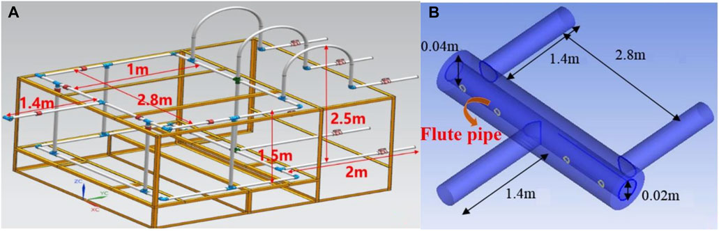
FIGURE 1. Flow distribution prototype for flow maldistribution test. (A) Schematic diagram of flow distribution prototype (B) Schematic diagram of flute pipe.
Experimental setup of flow maldistribution test is as shown in Figure 2. The transparent plexiglass pipe with a diameter of 50 mm and wall thickness of 5 mm is the main pipe and is connected with the tee. The red joint one is the connecting joint, the flute pipe is installed in the manifold, the diameter of the flute pipe is 20 mm, the total length is divided into 5 segments, the length of each section is 560 mm, and each section is connected by thread, with a total connection length of 2.8 m. A pressure sensor is installed on the conduit pipe from the 20 cm on both sides of the tee and at the outlet of the two leading-out pipes.
2) Experimental materials
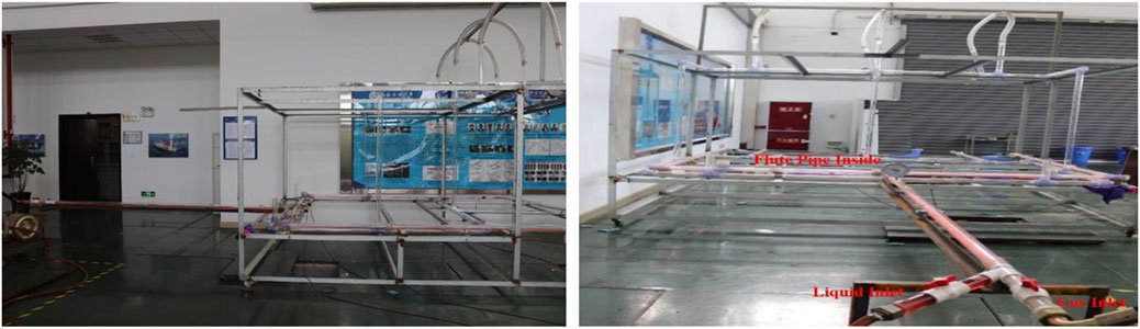
FIGURE 2. Experimental setup of flow maldistribution test.
Air, water, and pigment.
Experimental steps
1) Equipment inspection before the experiment. Whether there are leaks in the gas and liquid pipelines, whether the data acquisition system is running normally, and whether the gas booster pump and the pump operation and flow rate adjustment are available should be checked.
2) When the air compressor and water pump are turned on, after the gas flow and liquid flow are stable, the liquid flow is kept unchanged, and the gas flow is adjusted through the gas throttle valve. After the gas flow is stable, the gas flowmeter flow on the gas pipeline and the liquid flowmeter on the liquid pipeline should be read, and the inlet pressure in the corresponding inlet pipe and the experimental time of each group should be read and recorded.
3) The high-definition camera and the pressure sensor on the computer should be turned on, and the gas–liquid two-phase flow pattern changes and pressure data of the horizontal lead-in tube and horizontal outlet pipes 1 and 2 during the whole experiment should be recorded. At the same time, the timing begins by the timekeeper, and the operator begins to measure the liquid mass of the horizontal exit tube 1 and the horizontal outlet pipe 2 at the same time, while the rest of the personnel begin to measure the gas-phase wind speed at the two ends of the horizontal outlet pipe 1 and outlet pipe 2 with the wind anemometer. The experiment should be repeated twice again.
4) After the experimental test is completed, the wind speed at both ends of the outlet is recorded and the liquid weight of the two outlets is measured.
5) The liquid flow rate must be kept unchanged, the gas flow rate should be changed and the experiment should be carried out again until the upper and lower criticality of the stratified flow is determined and the experimental workload is completed at the end of the experiment.
6) The liquid flow rate should be changed, the gas flow rate through the gas throttle valve should be adjusted, and the above experimental steps should be repeated until all the tests are completed.
All the detailed experimental parameters are listed in Table 1.
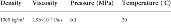
TABLE 1. Experimental parameters of flow maldistribution in the horizontal manifold.
Experimental phenomena
Flow rate of gas and liquid in the inlet under different flow pattern conditions is as shown in Table 2. The experimental phenomenon of flow maldistribution in stratified flow in a horizontal manifold is as shown in Figure 3. The stratification of the gas–liquid interface in the inlet pipe is obvious, and the interface ripple is serious, but the ripple is smaller and denser. The liquid and gas in outlet pipe 1 fully mix and move forward, and the liquid moves forward in a small wave shape, which is relatively regular. The gas–liquid migration phenomenon in outlet pipe 2 is similar to that in outlet pipe 1. The liquid and gas in outlet pipe 2 are fully mixed and moved forward, the liquid level fluctuation is relatively smooth, and the ripple is not serious. The liquid flow rate of outlet pipe 1 is slightly larger than that of outlet pipe 2, and the gas flow rate of exit tube 1 is larger than that of outlet pipe 2, resulting in a phenomenon of flow maldistribution.
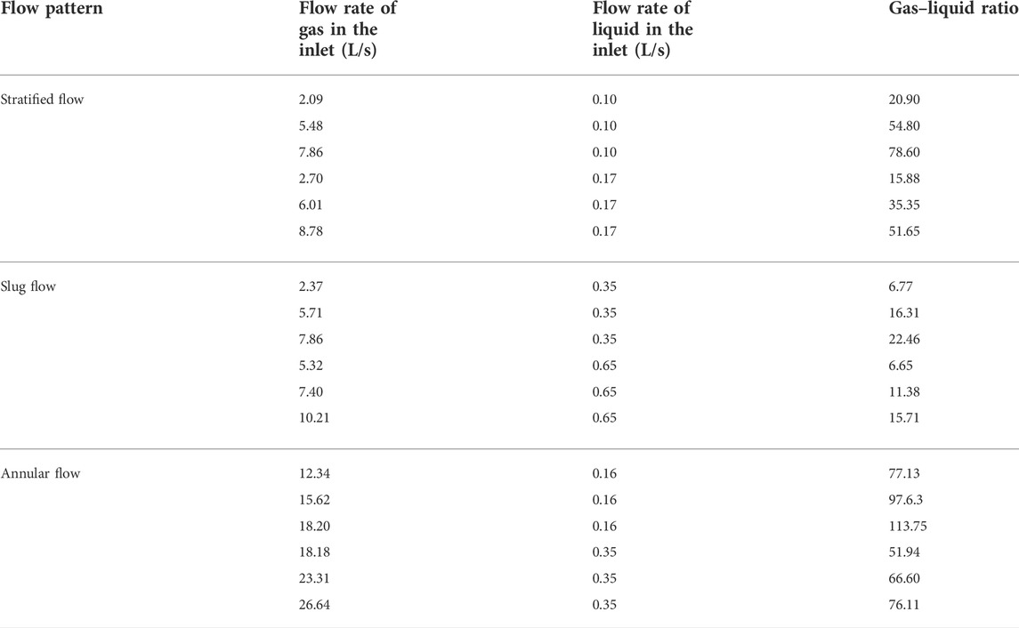
TABLE 2. Flow rate of gas and liquid in the inlet under different flow pattern conditions.
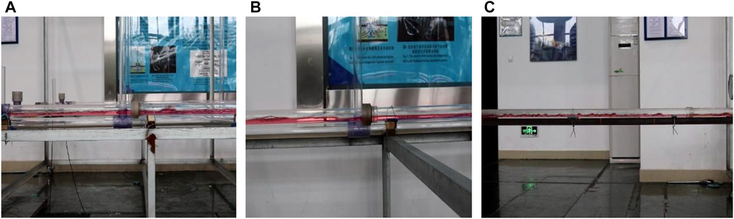
FIGURE 3. Experimental phenomenon of flow maldistribution in stratified flow in horizontal manifold [(A) outlet pipe 1, (B) outlet pipe 2, and (C) inlet pipe].
Test analysis of maldistribution of gas‐liquid two-phase flow in a horizontal pipeline
The calculation procedures of maldistribution degree for gas and water are shown as follows:
where
The flow pattern can be determined by many methods, and they all have their own merits and demerits. In this work, the flow pattern is determined by the gas–liquid ratio and the flow phenomenon of gas–liquid in the pipe, combined with the flow rate of gas and liquid meanwhile. The flow rate of gas and liquid in the inlet under different flow pattern conditions is shown as follows.
Maldistribution test of stratified flow in horizontal manifold without flute pipe
Through the analysis of histogram of gas–liquid ratio and maldistribution degree of liquid in stratified flow in horizontal manifold without flute pipe (as shown in Figure 4), it can be found that the overall trend of the maldistribution degree of liquid with the increase of gas–liquid ratio is as follows: first, the maldistribution degree of liquid is relatively stable, but some of them are large, and then there is a sharp zigzag change. The maldistribution degree of partial gas is 0, and when the gas–liquid ratio is 9.40, 29.30, 62.80, 68.40, 78.60, 86.40, 109.90, and 140.40, the maldistribution degree of liquid is the lowest to 0. When the gas–liquid ratio is 54.80, the peak value of maldistribution is 40%. When the gas–liquid ratio is 20.90, 42.30, 54.80, 74.35, 99.00, and 126.70, the value of maldistribution is 20%.
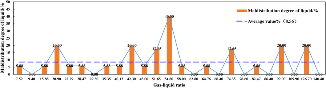
FIGURE 4. Histogram of gas–liquid ratio and maldistribution degree of liquid in stratified flow in horizontal manifold without flute pipes (liquid injection volume 0.10L/s+0.17L/s).
Through the analysis of histogram of gas–liquid ratio and maldistribution degree of gas in stratified flow in horizontal manifold without flute pipes (as shown in Figure 5), it is found that the overall trend of maldistribution degree of gas with the increase of gas–liquid ratio is as follows: first, the maldistribution degree of gas changes in a zigzag shape, and then the range of change becomes smaller. When the gas–liquid ratio is 9.40, the maldistribution degree of gas is the lowest, as low as 0, and when the gas–liquid ratio is 51.65, the maximum maldistribution degree of gas is 18.45%.
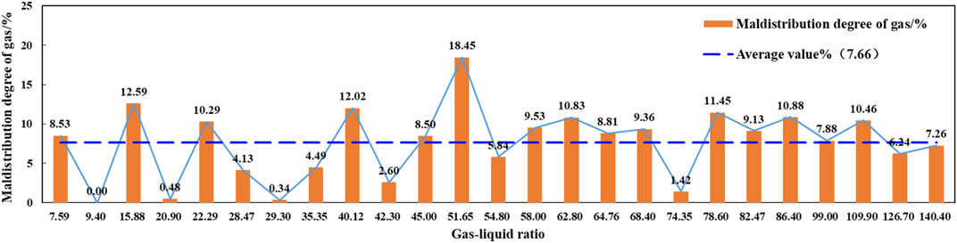
FIGURE 5. Histogram of gas–liquid ratio and maldistribution degree of gas in stratified flow in horizontal manifold without flute pipes (liquid injection volume 0.10L/s+0.17L/s).
Maldistribution test of stratified flow in horizontal manifold with flute pipe
The analysis of the histogram of gas–liquid ratio and maldistribution degree of liquid in stratified flow in horizontal manifold with flute pipe (Figure 6) show that the maldistribution degree of liquid changes sharply with the increase of gas–liquid ratio. When the gas–liquid ratio is 10.10, 30.00, 39.70, 54.70, 65.10, 84.70, and 101.60, the maldistribution degree of liquid is as low as 0.005%, and when the gas–liquid ratio is 72.47 and 82.35, the deviation degree is the highest, which is 52.94%.
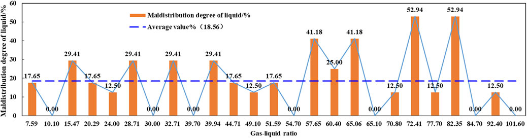
FIGURE 6. Histogram of gas–liquid ratio and maldistribution degree of liquid in stratified flow in horizontal manifold with flute pipes (liquid injection volume 0.10L/s+0.17L/s).
Through the analysis of histogram of gas–liquid ratio and maldistribution degree of gas in stratified flow in horizontal manifold with flute pipe (Figure 7), it is found that the overall trend of maldistribution degree of gas with the increase of gas–liquid ratio is as follows: the maldistribution degree of gas first increases with the increase of gas–liquid ratio, and then changes in a zigzag shape. When the gas–liquid ratio is 101.60, the maldistribution degree of gas is the smallest, as low as 0.79%, and when the gas–liquid ratio is 24.00, the maximum maldistribution degree of gas is 25.00%.
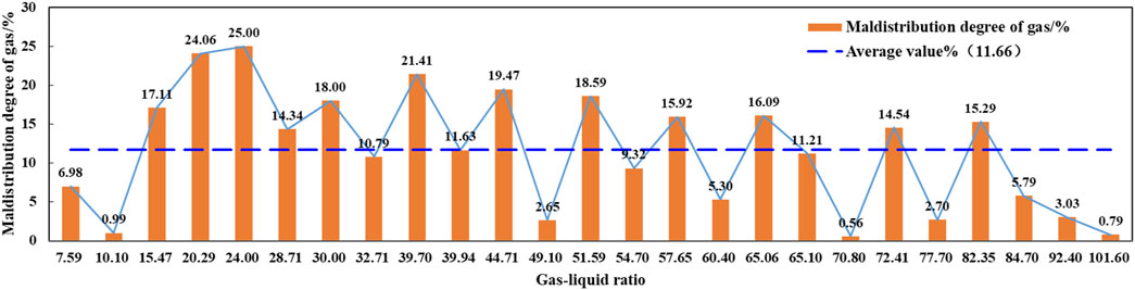
FIGURE 7. Histogram of gas–liquid ratio and maldistribution degree of gas in stratified flow in horizontal manifold with flute pipes (liquid injection volume 0.10L/s+0.17L/s).
Maldistribution test of slug flow in horizontal manifold without flute pipe
Through the analysis of histogram of gas–liquid ratio and maldistribution degree of liquid in slug flow in horizontal manifold without flute pipe (Figure 8), it is found that the overall trend of liquid maldistribution degree with the increase of gas–liquid ratio is that it fluctuates slightly at first, and then decreases to a certain extent and then tends to be relatively stable. When the gas–liquid ratio is 6.77, the maldistribution degree of liquid is the largest, which is 20.00%. Through the analysis of the histogram of gas–liquid ratio and maldistribution degree of gas in slug flow in horizontal manifold without flute pipe (Figure 9), it is found that the overall trend of maldistribution degree of gas is relatively stable with the increase of gas–liquid ratio, but there is a larger maldistribution degree of gas when the gas–liquid ratio is 27.43, which is 20.83%.
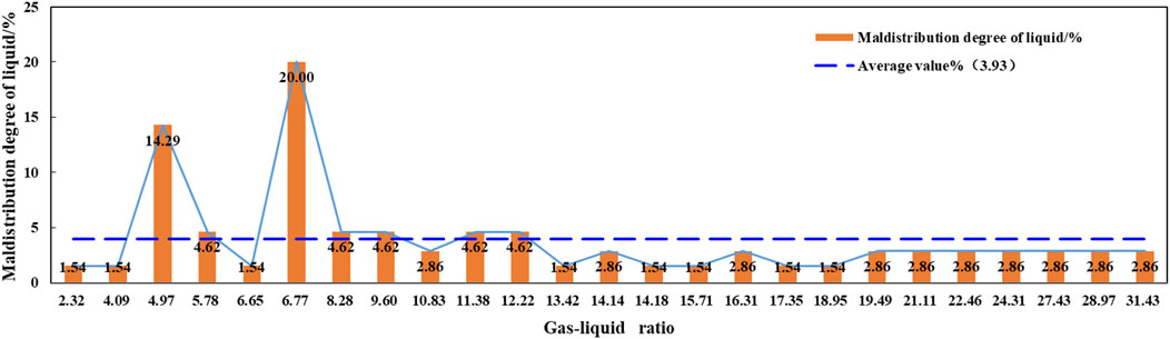
FIGURE 8. Histogram of gas–liquid ratio and maldistribution degree of liquid in slug flow in horizontal manifold without flute pipes (liquid injection volume 0.35L/s+0.65L/s).
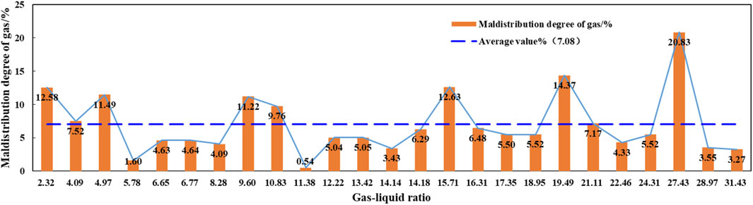
FIGURE 9. Histogram of gas–liquid ratio and maldistribution degree of gas in slug flow in horizontal manifold without flute pipes (liquid injection volume 0.35L/s+0.65L/s).
Maldistribution test of slug flow in horizontal manifold with flute pipe
Through the analysis of histogram of gas–liquid ratio and maldistribution degree of liquid in slug flow in horizontal manifold with flute pipe (Figure 10), it is found that the overall trend of the maldistribution degree of liquid with the increase of the gas–liquid ratio is that the maldistribution degree of liquid increases gradually with the gas–liquid ratio, then decreases sharply, and then increases sharply, and finally tends to be relatively stable. When the gas–liquid ratio is 1.94, the maldistribution degree of liquid is as low as 7.69%, and when the gas–liquid ratio is 16.14, the peak maldistribution degree of liquid is 47.69%.
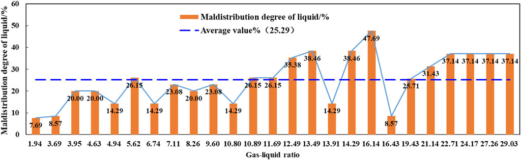
FIGURE 10. Histogram of gas–liquid ratio and maldistribution degree of liquid in slug flow in horizontal manifold with flute pipes (liquid injection volume 0.35L/s+0.65L/s).
Through the analysis of histogram of gas–liquid ratio and maldistribution degree of gas in slug flow in horizontal manifold with flute pipe (Figure 11), it is found that the overall trend of maldistribution degree of gas with the increase of gas–liquid ratio is that it changes in a zigzag shape at first, then the value is larger and more stable in the range of gas–liquid ratio of 10.89–13.49, and the maldistribution degree of gas is stable and small in the range of the gas–liquid ratio of 16.43–29.03. When the gas–liquid ratio is 4.94, the maldistribution degree of gas is the lowest, as low as 0.58%, and when the gas–liquid ratio is 46.67, the maximum maldistribution degree of gas is 48.90%.
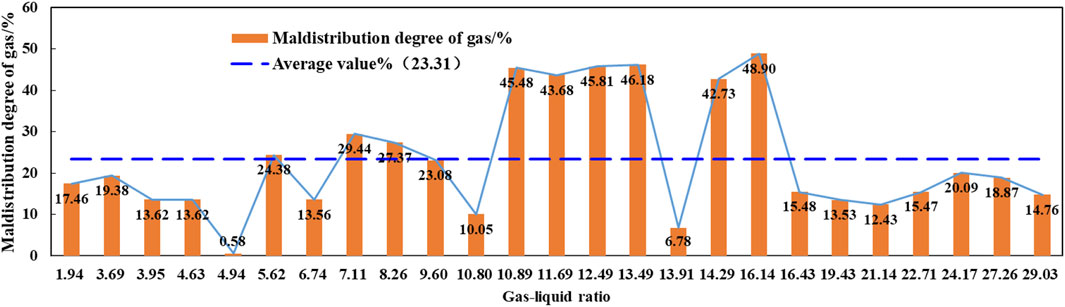
FIGURE 11. Histogram of gas–liquid ratio and maldistribution degree of gas in slug flow in horizontal manifold with flute pipes (liquid injection volume 0.35L/s+0.65L/s).
Maldistribution test of annular flow in horizontal manifold without flute pipe
Through the analysis of histogram of gas–liquid ratio and maldistribution degree of liquid in annular flow in horizontal manifold without flute pipes (Figure 12), it is found that the overall trend of maldistribution degree of liquid fluctuates with the increase of gas–liquid ratio, but the fluctuation range is not very large, and then decreases to be stable when it increases to 25%. When the gas–liquid ratio is 70.06 and 103.38, the maldistribution degree of liquid is as low as 0, and when the gas–liquid ratio is 89.38, the peak value of the maldistribution degree is 25.00%. Through the analysis of histogram of gas–liquid ratio and maldistribution degree of gas in annular flow in horizontal manifold without flute pipes (Figure 13), we can see that the overall trend of maldistribution degree of gas is zigzag with the increase of gas–liquid ratio. When the gas–liquid ratio is 71.60, the maldistribution degree of gas is the lowest, as low as 0.56%. When the gas–liquid ratio is 165.50, the maximum maldistribution degree of gas is 8.46%.
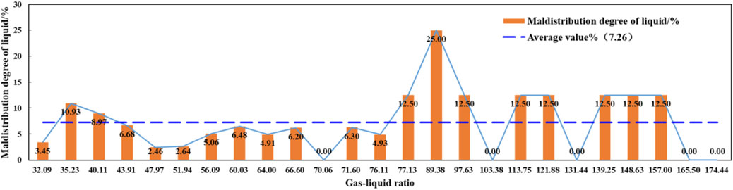
FIGURE 12. Histogram of gas–liquid ratio and maldistribution degree of liquid in annular flow in horizontal manifold without flute pipes (liquid injection volume 0.16L/s+0.35L/s).
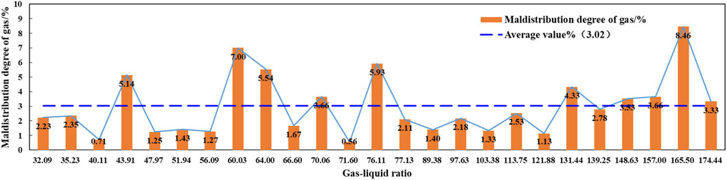
FIGURE 13. Histogram of gas–liquid ratio and maldistribution degree of gas in annular flow in horizontal manifold without flute pipes (liquid injection volume 0.16L/s+0.35L/s).
The comparative analysis shows that the horizontal manifold without a flute pipe is beneficial to control the maldistribution of liquid when the gas–liquid ratio is in the range of 32.09–76.11, and the horizontal manifold without a flute pipe is beneficial to control the maldistribution of gas when the gas–liquid ratio is in the range of 32.09–174.44.
Maldistribution test of annular flow in horizontal manifold with flute pipe
Through the analysis of histogram of gas–liquid ratio and maldistribution degree of liquid in annular flow in horizontal manifold with flute pipe (Figure 14), it can be seen that with the increase of gas–liquid ratio, the overall trend of maldistribution degree of liquid decreases slightly at first, then increases sharply, then the zigzag shape changes sharply, and then tends to be relatively stable. When the gas–liquid ratio is 46.67, the maldistribution degree of liquid is as low as 0, and the peak maldistribution degree is 48.57%.
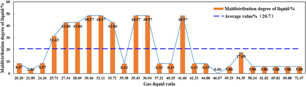
FIGURE 14. Histogram of gas–liquid ratio and maldistribution degree of liquid in annular flow in horizontal manifold with flute pipes (liquid injection volume 0.16L/s+0.35L/s).
Through the analysis of the histogram of gas–liquid ratio and maldistribution degree of gas in annular flow in horizontal manifold with flute pipes (Figure 15), it is found that the overall trend of maldistribution degree of gas is zigzag with the increase of gas–liquid ratio. When the gas–liquid ratio is 49.29, the maldistribution degree of gas is the lowest, as low as 1.19%. When the gas–liquid ratio is 46.67, the maximum maldistribution degree of gas is 24.46%.
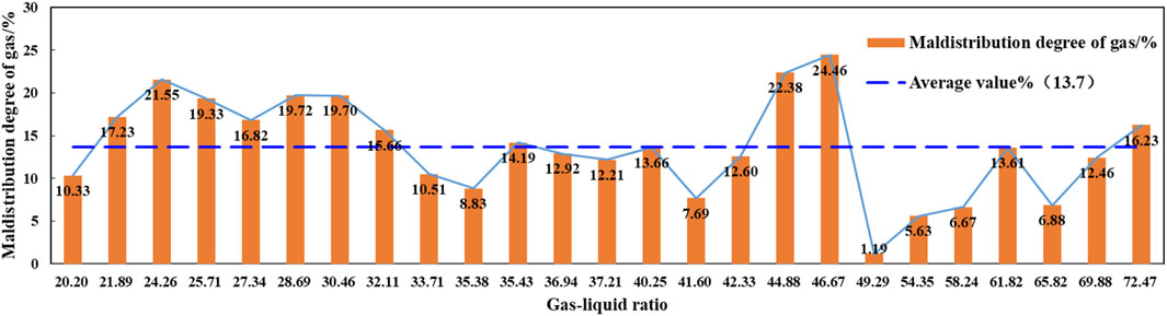
FIGURE 15. Histogram of gas–liquid ratio and maldistribution degree of gas in annular flow in horizontal manifold with flute pipes (liquid injection volume 0.16L/s+0.35L/s).
The comparative analysis shows that the addition of flute pipe into the horizontal manifold is beneficial to control the maldistribution degree of liquid when the gas–liquid ratio is in the range of 20.20–24.26 and 42.33–72.47, and the introduction of flute pipes is beneficial to control the maldistribution degree of gas when the gas–liquid ratio is in the range of 33.71–35.38, 41.60–42.33, and 49.29–69.88.
Analysis of maldistribution control in different flow patterns
According to the analysis of the maldistribution degree of liquid and gas of stratified flow, slug flow, and annular flow when flute pipe is considered and not considered, we obtained the scatter diagram of liquid maldistribution degree in different flow patterns in horizontal manifold with and without flute pipe and histogram of flow pattern and average liquid maldistribution degree in the horizontal manifold.
Through the analysis of the scatter diagram of liquid maldistribution degree in different flow patterns in horizontal manifold with and without flute pipes (Figures 16, 17), and the histogram of flow pattern and average liquid maldistribution degree in horizontal manifold (Figure 18), it is found that under the condition that the flute pipe is not added in the horizontal manifold, the average maldistribution degree of liquid in stratified flow, slug flow, and annular flow are 8.56, 5.16, and 7.26%, respectively. The average maldistribution degree of liquid under the three flow patterns is small as a whole, and the average maldistribution degree of liquid under the stratified flow condition is greater than that under the slug flow and annular flow conditions. Average maldistribution degree of liquid under the slug flow condition is less than that under the stratified flow and annular flow conditions.
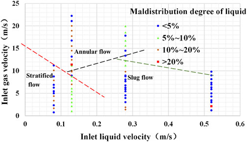
FIGURE 16. Scatter diagram of liquid maldistribution degree in different flow patterns in horizontal manifold without flute pipes.
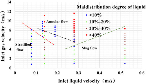
FIGURE 17. Scatter diagram of liquid maldistribution degree in different flow patterns in horizontal manifold with flute pipe.
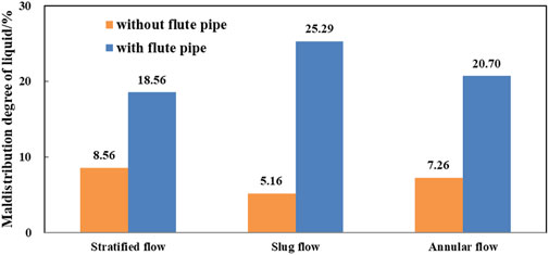
FIGURE 18. Histogram of flow pattern and average liquid maldistribution degree in the horizontal manifold.
Under the condition of introducing a flute pipe into the horizontal manifold, the average maldistribution degree of liquid in stratified flow, slug flow, and annular flow are 18.56, 25.29, and 20.70%, respectively. However, the average maldistribution degree of liquid under the condition of stratified flow is less than that of slug flow and annular flow. The average maldistribution degree of liquid under the condition of slug flow is greater than that of stratified flow and annular flow. Compared with the horizontal manifold with and without the introduction of a flute pipe, the absence of a flute pipe is beneficial to control the average maldistribution degree of liquid. The introduction of a flute pipe will aggravate the maldistribution degree of liquid, especially under the condition of slug flow pattern. This is because after the gas–liquid fluid enters the flute pipe, the cross-section becomes smaller and the gas–liquid velocity increases relatively. The flow of the liquid becomes more unstable, so the flow maldistribution is more likely to occur at the two outlets. Under the condition of the slug flow pattern, the gas–liquid interface is in direct contact with the upper part of the flute pipe due to violent fluctuations, which separates the gas phase located in the upper part of the pipe into an aeroelastic and forms the slug flow pattern.
Through the analysis of the scatter diagram of gas maldistribution degree in different flow patterns in horizontal manifold with and without flute pipes (Figures 19, 20), and the histogram of flow pattern and average gas maldistribution degree in horizontal manifold (Figure 21), it is found that under the condition that flute pipe is not added in the horizontal manifold, the average maldistribution degree of gas in stratified flow, slug flow, and annular flow is 7.66, 9.08, and 3.02%, respectively. The average maldistribution degree of gas under the three flow patterns is small as a whole, and the average maldistribution degree of gas in the slug flow condition is greater than that in the stratified flow and annular flow conditions. Under the condition of annular flow, the average maldistribution degree of gas is less than that of stratified flow and slug flow.
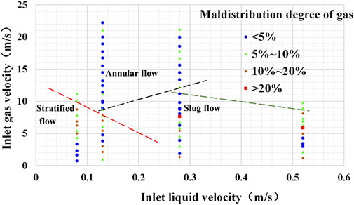
FIGURE 19. Scatter diagram of gas maldistribution degree in different flow patterns in horizontal manifold without flute pipe.
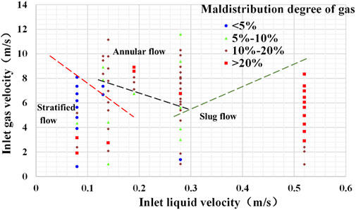
FIGURE 20. Scatter diagram of gas maldistribution degree in different flow patterns in horizontal manifold with flute pipe.
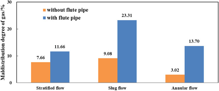
FIGURE 21. Histogram of flow pattern and average gas maldistribution degree in the horizontal manifold.
When the flute pipe is introduced into the horizontal manifold, the average maldistribution degree of gas in stratified flow, slug flow, and annular flow are 11.66, 23.31, and 13.70%, respectively. However, the average maldistribution degree of gas under the condition of stratified flow is less than that of slug flow and annular flow. The average maldistribution degree of gas under the condition of slug flow is greater than that of stratified flow and annular flow. The introduction of a flute pipe will aggravate the maldistribution degree of gas, especially under the condition of an annular flow pattern. This is because after the gas–liquid fluid enters the flute pipe, the cross-section becomes smaller and the gas–liquid velocity increases relatively. The flow of the gas becomes more unstable, so the flow maldistribution is more likely to occur at the two outlets. Under the condition of an annular flow pattern, the central part of the flute pipe is a gas core with droplets, and there is a liquid film on the pipe wall. Under the influence of gravity, the liquid film of the lower pipe wall is thicker than that of the upper tube wall.
Through comparative analysis of the horizontal manifold with and without the introduction of flute pipe, the absence of flute pipes is conducive to the control of the average maldistribution degree of gas. Under the condition of introducing a flute pipe, it is disadvantageous to the control of the average maldistribution degree of liquid and gas in the slug flow pattern.
Conclusion
1) The influence of flow pattern and the introduction of flute pipes on the maldistribution degree of liquid and gas under the condition of different gas–liquid ratios is revealed.
① When the flute pipe is not introduced into the horizontal pipe under the condition of stratified flow, it is beneficial to control liquid maldistribution when the gas–liquid ratio is in the range of 22.29–40.12 and 58.00–86.40, and it is beneficial to control gas maldistribution when the gas–liquid ratio is in the range of 7.59–45.00 and 54.80–140.40.
② When the flute pipe is introduced into the horizontal pipe under the condition of stratified flow, it is beneficial to control both liquid and gas maldistribution when the gas–liquid ratio is in the range of 84.70–101.60, 77.70, 70.80, 49.10, and 10.10.
③ When the flute pipe is not introduced into the horizontal pipe under the condition of slug flow, it is beneficial to control liquid maldistribution when the gas–liquid ratio is in the range of 5.78–6.65 and 8.28–31.4, and it is beneficial to control gas maldistribution when the gas–liquid ratio is in the range of 4.09–10.83, 12.22–18.95, 21.11–24.31, and 54.80–140.40.
④ When the flute pipe is introduced into the horizontal pipe under the condition of slug flow, it is beneficial to control liquid maldistribution when the gas–liquid ratio is in the range of 1.94–3.69 and 16.43, and it is beneficial to control gas maldistribution when the gas–liquid ratio is in the range of 16.43–22.71, 4.94, and 13.91.
⑤ When the flute pipe is not introduced into the horizontal pipe under the condition of annular flow, it is beneficial to control liquid maldistribution when the gas–liquid ratio is in the range of 3.45–4.93, 165.50–174.44, 103.38, and 131.44, and it is beneficial to control gas maldistribution when the gas–liquid ratio is in the range of 2.23–174.44.
⑥ When the flute pipe is introduced into the horizontal pipe under the condition of annular flow, it is beneficial to control liquid maldistribution when the gas–liquid ratio is in the range of 46.67–49.29 and 58.24–72.47, and it is beneficial to control gas maldistribution when the gas–liquid ratio is in the range of 49.29–58.24 and 65.82.
2) A maldistribution control scheme of gas–liquid two-phase flow in the horizontal pipeline is proposed: it is more beneficial to the control of average liquid maldistribution in the horizontal manifold of slug flow pattern without the introduction of flute pipe; it is more beneficial to the control of average gas maldistribution in the horizontal manifold of annular flow pattern without the introduction of flute pipe; it is more beneficial to the control of both average liquid and gas maldistribution in the horizontal manifold of annular flow pattern without the introduction of flute pipe.
Data availability statement
The original contributions presented in the study are included in the article/Supplementary Material; further inquiries can be directed to the corresponding authors.
Author contributions
NW, LJ, and SF contributed to conception and design of the study. NW, LJ, and AL established the experiment model. HL, SZ, CZ, and JX performed the experiments, calculations and analysis. LJ wrote the first draft of the manuscript. NW, and SF wrote sections of the manuscript. All authors contributed to manuscript revision, read, and approved the submitted version.
Funding
The work described in this article is supported by the National Natural Science Foundation of China (U20B6005 and 51874252), the National Key Research and Development Program of China (2021YFC28000903), 111 Project (D21025), and the High-end Foreign Expert Introduction Program (G2021036005L).
Conflict of interest
AL was employed by the company Chuanqing Drilling Engineering Company.
The remaining authors declare that the research was conducted in the absence of any commercial or financial relationships that could be construed as a potential conflict of interest.
Publisher’s note
All claims expressed in this article are solely those of the authors and do not necessarily represent those of their affiliated organizations, or those of the publisher, the editors, and the reviewers. Any product that may be evaluated in this article, or claim that may be made by its manufacturer, is not guaranteed or endorsed by the publisher.
References
Chen, H., Li, Q., Yao, H., Li, Y., and Gong, J. (2019). Study on the flow maldistribution problem of the gathering and transportation manifold for gas-liquid two phase flow. Oil-Gas Field Surf. Eng. 38 (3), 1–6. doi:10.3969/j.issn.1006-6896.2019.03.001
Duan, F., and Liang-cai, C. (2016). Numerical simulation of flow distribution characteristics of manifold with mid-plate. Pipeline Tech. Equip. 4, 1–4. doi:10.3969/j.issn.1004-9614.2016.04.001
Hao, Y., Wang, Y., and Hu, T. (2016). The flow distribution in the parallel tubes of the cavity receiver under variable heat flux. Appl. Therm. Eng. 108 (1), 641–649. doi:10.1016/j.applthermaleng.2016.07.168
Kaichiro, M., and Ishi, M. (1984). Flow regime transition criteria for upward two-phase flow in vertical tubes. Int. J. Heat. Mass Transf. 27 (5), 723–737. doi:10.1016/0017-9310(84)90142-x
Kim, S., Choi, E., and Cho, Y. I. (1995). The effect of header shapes on the flow distribution in a manifold for electronic packaging applications. Int. Commun. Heat Mass Transf. 22 (3), 329–341. doi:10.1016/0735-1933(95)00024-s
Lahey, R. T. (1986). Current understanding of phase separation mechanisms in branching conduits. Nucl. Eng. Des. 95, 145–161. doi:10.1016/0029-5493(86)90043-9
Lee, J., and Lee, S. (2004). Distribution of two- phase annular flow at header - channel junctions. Exp. Therm. Fluid Sci. 28 (3), 217–222. doi:10.1016/s0894-1777(03)00042-6
Li, X. (2017). “Simulation of flow distribution characteristics of natural gas liquefaction heat exchanger networks,” (China: Shandong University). Master thesis.
Li, Y. (2010). “Experimental and numerical simulation of gas-liquid two-phase flow in distribution header,” (Beiging: North China Electric Power University). Doctoral thesis.
Marchitto, A., Fossa, M., and Guglielmini, G. (2012). The effect of the flow direction inside the header on two-phase flow distribution in parallel vertical channels. Appl. Therm. Eng. 36, 245–251. doi:10.1016/j.applthermaleng.2011.10.008
McQuillan, K. W., and Whalley, P. B. (1985). Flow patterns in vertical two-phase flow. Int. J. Multiph. Flow 11 (2), 161–175. doi:10.1016/0301-9322(85)90043-6
Miao, Z. (1999). Flow characteristics of single phase fluid in multiorifice distributing pipe and collecting pipe. J. Shanghai Jiaot. Univ. 33 (3), 297–300.
Wang, D. (2012). Research on piccolo heat and flow distribution of civil aircraft anti-ice system. Civ. Aircr. Des. Res. 11, 1–5. doi:10.19416/j.cnki.1674-9804.2012.s1.041
Wang, Q., and Newby, B. M. Z. (2018). Layer-by-layer polyelectrolytes coating of alginate microgels for sustained release of sodium benzoate and zosteric acid. J. Drug Deliv. Sci. Technol. 46(37), 46–54. doi:10.1016/j.jddst.2018.04.019
Yan, L. (2019). Study on the application of variable diameter flute tube shunt technology in multi-on-line heat recovery. Electron. World 15, 196–197.
Yang, L. M., and Azzopardi, B. J. (2007). Phase split of liquid-liquid two-phase flow at a horizontal T-junction. Int. J. Multiph. Flow 33 (2), 207–216. doi:10.1016/j.ijmultiphaseflow.2006.08.004
Zhang, J., Guan, T., and Shan, Y. (2017). Influence of piccolo tube parameters on temperature distribution on hot-air anti-icing concave surface. J. Nanjing Univ. Aeronautics Astronautics 49 (5), 669–675. doi:10.16356/j.1005-2615.2017.05.010
Zhou, J., Sun, Z., Ding, M., Bian, H., Zhang, N., and Meng, Z. (2017). CFD simulation for flow distribution in manifolds of central- type compact parallel flow heat exchangers. Appl. Therm. Eng. 126, 670–677. doi:10.1016/j.applthermaleng.2017.07.194
Keywords: maldistribution, horizontal pipeline, Gas‐liquid two-phase flow, flow pattern, experimental investigation
Citation: Wei N, Jiang L, Fan S, Liu A, Li H, Zhang S, Zhang C and Xue J (2022) Experimental investigation of maldistribution characteristics of gas‐liquid two-phase flow in a horizontal pipeline. Front. Earth Sci. 10:853809. doi: 10.3389/feart.2022.853809
Received: 13 January 2022; Accepted: 25 August 2022;
Published: 27 September 2022.
Edited by:
Huazhou Li, University of Alberta, CanadaCopyright © 2022 Wei, Jiang, Fan, Liu, Li, Zhang, Zhang and Xue. This is an open-access article distributed under the terms of the Creative Commons Attribution License (CC BY). The use, distribution or reproduction in other forums is permitted, provided the original author(s) and the copyright owner(s) are credited and that the original publication in this journal is cited, in accordance with accepted academic practice. No use, distribution or reproduction is permitted which does not comply with these terms.
*Correspondence: Na Wei, MTQzNDc4NTM0MEBxcS5jb20=; Lin Jiang, bGluamlhbmdfMjAyMEAxNjMuY29t; Shuanshi Fan, MTgwOTY1NDIzMUBxcS5jb20=