 Qiang Zhang1
 Xia Yan
- 1CNOOC EnerTech-Drilling and Production Co., Tianjin, China
- 2School of Petroleum Engineering, China University of Petroleum (East China), Qingdao, China
The nonuniform distribution of proppant in hydraulic fractures is an essential factor determining the accuracy of well performance evaluation in shale gas reservoirs. In particular, unpropped and propped parts hold distinct closure behavior. To study the impacts of distinct closure behavior between unpropped and propped parts in fracture on gas production, we combine the proppant transport simulation and the 3D hydromechanical coupling simulation. This study quantitatively indicates the significant effects of nonuniform proppant distribution and fracture closure on well performance in shale gas reservoirs. By comparing the well performances with three kinds of typical proppant distribution at the same injection volume, the distribution accumulating near the wellbore is recommended as it can reduce the impact of unpropped fracture and exploit more gas. In addition, the cases with higher natural fracture permeability are found to have less difference in the well performance with different proppant coverages. Therefore, the impacts of nonuniform proppant distribution and fracture closure on well performance in shale gas reservoirs should be investigated comprehensively.
Introduction
Hydraulic fracturing has been a key technology for the economic exploitation of shale resources (Longlong, 2014; Yang et al., 2015; Song et al., 2016; Moghadasi et al., 2019; Yan, 2021). During the treatments of hydraulic fracturing, a great deal of slickwater and proppants is pumped to form hydraulic fractures in the shale formation. Within these hydraulic fractures, the proppant distribution is usually nonuniform, and the unpropped and propped parts hold distinct closure behavior (Li et al., 2020; Manchanda, 2020; Li and Voskov, 2021). Meanwhile, the distinct closure behavior conversely results in different stress-related conductivity for the propped and unpropped regions, which has a great effect on gas transport (Shen et al., 2019; Liu, 2020; Yan et al., 2020). Therefore, the nonuniform proppant distribution and fracture closure should be considered for accurately evaluating the well performance in shale gas reservoirs.
Placement of injected proppant in the fracture is one of the key factors determining fracture flow capacity after hydraulic fracturing (Liu, 2020; Yan et al., 2020). The mechanism of multiphase flow with proppant is relatively complex and needs to be further studied. Limitation of the formation environment makes direct monitoring of fracturing slurry flow impossible. Currently, a series of lab-scale experimental models built by transparent glass plates have been applied to search rules of sanding patterns (Tong and Mohanty, 2016; Ray, 2017; Tong et al., 2018). This kind of laboratory-based research and analysis is difficult to be directly applied to oilfield scale prediction, and thus numerical simulation becomes a feasible choice. In addition, the type of Lagrangian-based simulation always processes particles or particle clusters into a single tracking object, which requires a huge amount of calculation and is very challenging to achieve large-scale simulation such as the so-called DDPM(Hu et al., 2018), CFD-DEM (Zeng et al., 2016; Zhang et al., 2017; Wang et al., 2019; Zhu et al., 2019; Zhu et al., 2020), and MP-PIC methods (Zeng et al., 2019; Mao et al., 2021). On the contrary, the Eulerian-based scheme is thought to be more efficient which treats the particle phase as one of the continuous phases. For example, many study results of proppant distribution in long fracture by the two-fluid model (TFM) (Han, 2016; Huang, 2017; Wen et al., 2020) have been reported. To simulate the proppant flow in a fracture of 100 m long and 20 m high, the Eulerian granular model is used.
A number of reported studies, which investigated the impacts of proppant distribution and fracture closure on the well performance in shale gas reservoirs, are summarized as follows: Sierra et al.(Sierra et al., 2014) and Cipolla et al. (Cipolla et al., 2009; Cipolla et al., 2010) investigated the effects of the high-conductivity arch, unpropped fracture conductivity, and proppant distribution on gas production; however, they did not consider the fracture closure. Lee et al. (Lee et al., 2016) proposed the numerical model incorporating fracture closure to study the influence of proppant distribution in fracture on cumulative gas production. Liu et al.(Liu et al., 2018; Liu et al., 2019) studied the effects of fracture closure and proppant distribution on water flowback and gas production by using geomechanical simulation and flow simulation separately. Mao et al. (Mao et al., 2021) developed a MP-PIC-EDFM coupling system to evaluate the impact of proppant pumping schedules on gas production. However, their study is mainly focused on the fluid flow aspect, and the geomechanical effects have not been considered in detail. Zhou et al. (Zhou et al., 2019) and Zheng et al. (Zheng, 2019; Zheng et al., 2020) conducted the hydromechanical coupling simulations to study the impacts of proppant distribution and closure of fracture on cumulative gas production, while they ignored the displacement discontinuity at hydraulic fractures, which is significant for the stress change around these fractures. Due to the geomechanical effects being considered by using the over-simplification method in these studies, Yan et al. (Yan et al., 2020) developed a fully coupled geomechanics and gas transport model, in which the displacement discontinuity was simulated by using the stabilized extended finite element method, to investigate the impacts of partially supported fracture closure on well performance in shale gas reservoirs. However, the nonuniform proppant distribution is artificial in their study. In this study, the proppant transport simulation will be carried out to provide a more reliable nonuniform proppant distribution, and then the influence of proppant distribution patterns and fracture closure on well performance will be studied by using the fully coupled geomechanics and gas transport model.
This article is structured as follows: the numerical models for proppant transport and gas production are illustrated in Section 2; the impacts of proppant distribution patterns and fracture closure on gas production performance are analyzed in Section 3; in Section 4, some conclusions are provided.
Methodology
The schematic workflow for studying the impacts of nonuniform proppant distribution and fracture closure on shale gas production includes two procedures: proppant transport simulation and hydromechanical coupling simulation, as shown in Figure 1. First, we use the Eulerian granular model (Han, 2016) (EGM) to simulate the proppant transport and obtain its nonuniform distribution in hydraulic fractures. Then, we conduct the hydromechanical coupling simulation to find the impacts of fracture closure and nonuniform proppant displacement on well performance in a 3D shale reservoir.
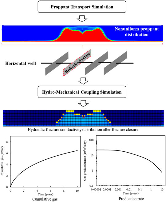
FIGURE 1. Schematic workflow for studying the impacts of heterogenous proppant distribution and fracture closure on shale gas production.
Proppant Transport Simulation
The proppant transport simulations are conducted based on the EGM, and the main model details are described as follows: the main phase in the EGM is the fluid phase and shares the same single pressure as the other solid phase. All the phases are treated as continuous, and the phase volume fraction is used to distinguish the computational region taken by various phases.
The mass conservation equation can be written as (Han, 2016):
where p and q are the subscripts for representing different phases,
where
Please note that the mass conservation and momentum balance equations of each phase are solved separately and then coupled with the mass and momentum exchange coefficients (Han, 2016). The numerical simulations are conducted by using ANSYS Fluent software. The reliability and accuracy of EGM have been verified by comparing it with experimental results in our previously published work (Wang, 2021). The proppant distribution results obtained by numerical simulation agree well with experimental results in the work of Tong, S. et al. (Tong and Mohanty, 2016).
Hydromechanical Coupling Simulation
Figure 2 shows the schematic of a typical shale gas reservoir, which consists of two sections. The darker section indicates the stimulated reservoir volume (SRV) including hydraulic fractures and natural fractures, while the other section outside the SRV contains few fractures. Therefore, the hybrid model (Yan, 2018; Yan et al., 2018) consisting of the embedded discrete fracture model, multiple porosity model, and single porosity model (Yan et al., 2016; Yan et al., 2019) will be used to evaluate the gas well performance.

FIGURE 2. Schematic diagram of a typical shale gas reservoir.
To reduce the simulation complexity and clearly investigate the effects of nonuniform proppant distribution and fracture closure on gas production, the single-phase gas model considering adsorption/desorption and Klinkenberg effects is applied to describe the gas transport in shale reservoirs (Yan et al., 2020), and its mass conservation equation is
where ϕ is the Lagrange porosity, in which the influences of fluid pressure and effective stress on pore deformation are fully considered (Yan, 2018), ρg represents gas density, m denotes the adsorption/desorption term, which is only for the shale matrix and could be calculated with the Langmuir’s isotherm (Langmuir, 1917), k indicates the absolute permeability, µ represents gas viscosity, b is the Klinkenberg coefficient incorporating gas-slippage effect (Wu et al., 2014), p indicates gas pressure; g and D represent gravity acceleration and depth, respectively, n is the normal vector of boundary Г, and q is the sink/source term on domain Ω.
The quasi-static geomechanics model (Shao, 2021; Zhang, 2021; Zhang et al., 2021) considering displacement discontinuity is used to describe the reservoir deformation and fracture closure, and its governing equation is
where b indicates the body force vector, and with the sign convention (i.e., negative for compression and positive for tension), the total stress tensor σ of the hybrid model is written as (Yan et al., 2020):
where C and α denote the elasticity tensor and Biot coefficient for single porosity model, respectively, I indicates the unit tensor, Cup, Kdr, and bl denote the upscaled elasticity tensor, drained bulk modulus, and the coupling parameter for the multiple porosity model (Yan, 2018). The small deformation assumption is adopted here, and thus the strain tensor ε can be written as:
where u indicates the displacement vector,
The flow and geomechanics boundary conditions are
where v indicates the gas flow rate;
where fs denotes the general stress–strain relationship of proppant compression, and εs is the proppant normal strain. On the other hand, the effective stress equation for unpropped fracture closure is (Yan et al., 2020)
where dHF indicates current fracture aperture, and En is the normal penalty parameter. Note that Eq. (10) permits a small interpenetration for fracture faces because its value is infinitesimal.
As the properties of matrix and fractures are affected by reservoir deformation, the matrix’s dynamic permeabilities (km), hydraulic fractures (kHF), and natural fractures (kf) are adopted here:
where subscripts m, f, HF, and 0 represent matrix, natural fracture, hydraulic fracture, and initial state, respectively; Kf is the drained bulk modulus for natural fracture; εv indicates volumetric strain; fk denotes the general relationship between effective stress and proppant permeability; and dHFmin indicates the minimum hydraulic aperture of unpropped fracture.
The developed fully coupled gas transport and geomechanics model can be solved by using our in-house hydromechanical coupling simulator. In this simulator, the flow and geomechanics models are discretized through the stabilized extended finite element method and the finite volume method. The coupled model is solved utilizing a sequential implicit method. The detailed numerical procedure and model verification can be found in our previous studies (Yan, 2018; Yan et al., 2018; Yan et al., 2019; Yan et al., 2020).
Results and Discussion
In this section, some numerical examples will be carried out to research the impacts of nonuniform proppant displacement and fracture closure on gas production performance. In the proppant transport simulation, the fixed time step (i.e., 1 s) is adopted to ensure that the moving distance of material in each step is the size of one or two grids, while the variable time step is used in the hydromechanical coupling simulation. We first set the initial time step and max time step, and then the time step would be reduced multiply, if the convergence solution cannot be obtained with the current time step. Conversely, if the convergence solution is obtained with the current time step, the next time step would be increased in multiples or kept the same. In addition, the time step cannot be over the max time step. In the following examples, the initial time step and max time step are 1 s and 100 days, respectively.
To reduce the computational costs, we only simulate one stage within a shale reservoir in 3D (Figure 3A). A horizontal well as well as the proppant injector is set at the hydraulic fracture center. The outer flow boundary is closed. The two stresses (35 MPa and 40 MPa) in the horizontal direction and the overburden stress (30 MPa) are applied on the back, right, and top boundaries, respectively. In addition, the roller constraint is applied to the other boundaries. Table 1 gives the model parameters, and the stress-dependent normalized fracture conductivity and the stress–strain curve for proppant compression are presented in Figure 4. The geometry discretization of this model is plotted in Figure 3B. Note that the surrounding formation is impermeable, and it is used to accurately consider geomechanical effects.
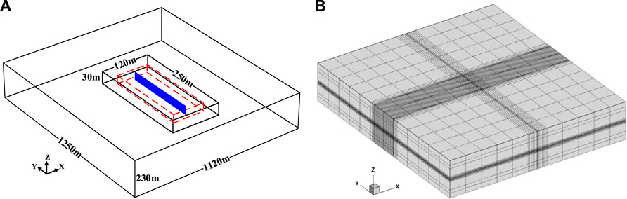
FIGURE 3. Schematic diagram of the 3D reservoir model (A) and its geometry discretization (B).
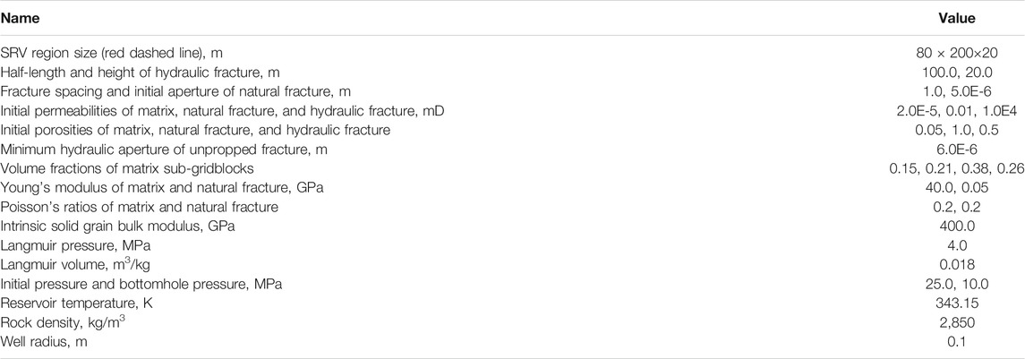
TABLE 1. Model parameters used in shale gas production simulation.
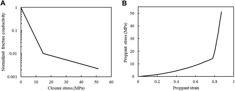
FIGURE 4. Stress-dependent normalized fracture conductivity (A) and the nonlinear stress–strain for proppant compression (B) (Yan et al., 2020).
As concluded in our previous research (Wang, 2021), various proppant distributions can be obtained for different pumping schemes. For example, the proppant distributions are adjusted by controlling the fracturing fluid viscosity in this work. It should be noted that a similar effect can be achieved by altering other injection conditions. Overall, three representative distribution types are selected from a series of cases: proppants accumulate near the wellbore (Type 1), proppants transport to the location away from the wellbore (Type 2), and proppants screen out in fracture tip (Type 3), as shown in Figure 5. With the same injection volumes, which distribution would have the best gas production is a valuable question. At first, we mimic the fracturing treatment with high pressure fluid (42 MPa) within hydraulic fracture to obtain its initial aperture distribution. Then, the proppant transport simulation is conducted to form the proppant distribution within the hydraulic fracture, and the simulation parameters are summarized in Table 2.
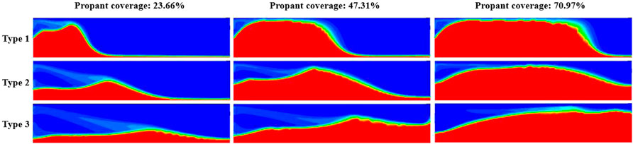
FIGURE 5. Proppant distributions with different injection volumes, and the half-profiles are shown due to symmetry.
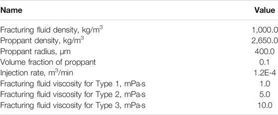
TABLE 2. Parameters used for proppant transport simulations.
The proppant distributions with different injection volumes (proppant coverage, the ratio of the propped fracture area to the total fracture area) are shown in Figure 5. The comparisons of conductivity distribution, σxx distribution (only the reservoir part), and cumulative gas among various cases after 10 years are compared in Figures 6–8, respectively. First, we can find that the conductivity of the supported fracture area is significantly higher than that of the unpropped part, while the highest conductivity is located at the interface between propped and unpropped parts because there is a high conductivity arch at the interface as the result of different closure behaviors for propped and unpropped parts. We can also find that σxx around the part supported by the proppant is higher than that of the unpropped area. Because the part supported by the proppant is stiffer than the unpropped part, which can resist higher closing. From Figure 8, it can be concluded that Type 1 has the best gas production as its cumulative gas is the highest for all injection volumes. On the contrary, Type 3 has the worst gas production because the wellbore cannot be effectively supported in this type. Another interesting observation is that σxx of the reservoir part decreases as the cumulative gas increases. Because when pressure decreases in the reservoir part, the region outside of the reservoir part suffers higher stress to support the boundary force.
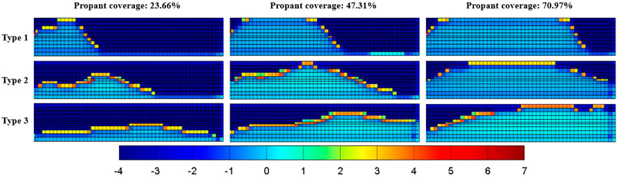
FIGURE 6. Comparison of the conductivity map after 10 years between cases with various proppant distributions, lg (kHF·dHF/md-m).
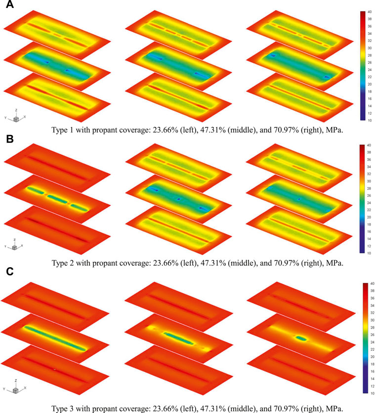
FIGURE 7. Comparison of σxx distribution after 10 years between cases with various proppant distributions. The profiles are shown in three layers (top, middle, and bottom), and the z length is shown nine times of the actual size for clarity. (A) Type 1 with proppant coverage: 23.66% (left), 47.31% (middle), and 70.97% (right), MPa. (B) Type 2 with proppant coverage: 23.66% (left), 47.31% (middle), and 70.97% (right), MPa. (C) Type 3 with proppant coverage: 23.66% (left), 47.31% (middle), and 70.97% (right), MPa.
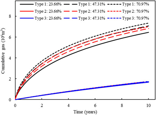
FIGURE 8. Comparison of cumulative gas after 10 years between cases with various proppant displacements.
In addition, to illustrate the sensitivity of gas production to the conductivity of unpropped fracture, three conductivities (0.018-m, 0.090-m, and 0.180-m) are applied for unpropped fracture. Table 3 lists the cumulative gas for different cases after 10 years. It indicates that gas production correlates positively with the conductivity of unpropped fracture, especially the gas production of the distribution type, in which the wellbore cannot be effectively supported, is the most affected. As the conductivity of unpropped fracture is usually low and difficult to improve, the completion design should strive to form Type 1 proppant distribution to reduce the impact of unpropped fracture and exploit more gas with the same proppant injection volume.
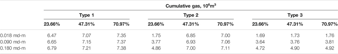
TABLE 3. Cumulative gas for different cases after 10 years.
Last, we study the influence of proppant coverage for Type 1 on gas production under different natural fracture permeability (0.001 mD, 0.01 mD, and 0.1 mD). Figure 9 shows the comparison of cumulative gas between different cases after 10 years. We can see that cumulative gas increases as the proppant covered coverage increases under different natural fracture permeability; however, the increase of cumulative gas caused by covered coverage increasing is negligible when natural fracture permeability is high enough. Therefore, the proppant covered coverage in the hydraulic fracture can be appropriately reduced by increasing natural fracture permeability.
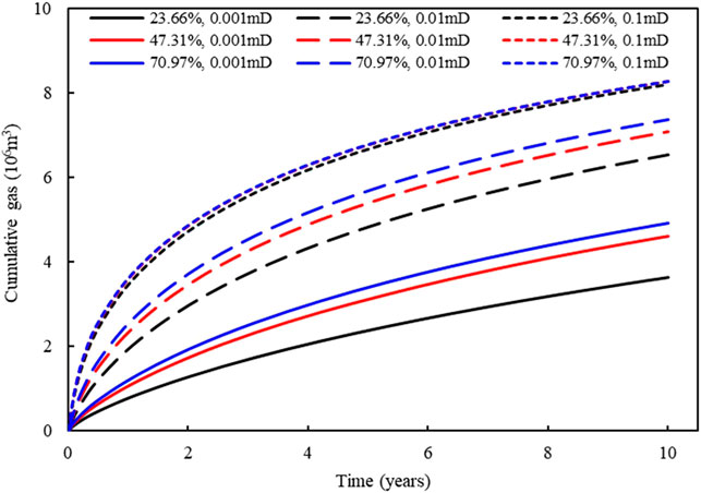
FIGURE 9. Comparison of cumulative gas between different cases after 10 years.
Conclusion
In this work, the gas production in shale reservoirs considering nonuniform proppant distribution and fracture closure is studied by combing proppant transport simulation and hydromechanical coupling simulation. Specifically, we use the EGM to simulate the proppant transport and obtain its nonuniform distribution in hydraulic fractures, and then we conduct the hydromechanical coupling simulation to simulate the impacts of nonuniform proppant distribution and fracture closure on gas production performance in a 3D shale reservoir. The following insights are obtained: 1) the nonuniform proppant distribution and fracture closure have a significant influence on gas production performance; 2) Type 1 proppant distribution is recommended as it can reduce the impact of unpropped fracture and exploit more gas with the same proppant injection volume; 3) higher natural fracture permeability leads to less impact of proppant coverage on gas production. Therefore, the nonuniform proppant distribution and fracture closure should be considered for accurately evaluating the well performance in shale gas reservoirs. As there is no limit to fracture number and fracture pattern in the proposed method, the large-scale implementation with a complex fracture pattern will be realized in our future study.
Data Availability Statement
The raw data supporting the conclusion of this article will be made available by the authors, without undue reservation.
Author Contributions
XY and XW: conceptualization; QZ, XY, and XW: methodology; QZ: software; XY and QZ: validation; GF: formal analysis; WY: investigation; YY: resources; QZ: data curation; XY and QZ: writing—original draft preparation; KZ: writing—review and editing; QZ: visualization; XY: supervision; WY: project administration; YY: funding acquisition. All authors have read and agreed to the published version of the manuscript.
Funding
This work was supported by the National Natural Science Foundation of China (52004321 and 52034010), Natural Science Foundation of Shandong Province, China (ZR2020QE116), and Fundamental Research Funds for the Central Universities (20CX06025A, 21CX06031A, and YCX2021033).
Conflict of Interest
Authors QZ, GF, WY, and YY are employed by CNOOC EnerTech-Drilling and Production Co.
The remaining authors declare that the research was conducted in the absence of any commercial or financial relationships that could be construed as a potential conflict of interest.
Publisher’s Note
All claims expressed in this article are solely those of the authors and do not necessarily represent those of their affiliated organizations, or those of the publisher, the editors, and the reviewers. Any product that may be evaluated in this article, or claim that may be made by its manufacturer, is not guaranteed or endorsed by the publisher.
References
Cipolla, C. L. L., Warpinski, N. R. R., Mayerhofer, M. J. J., Lolon, E. P. P., and Vincent, M. C. C. (2010). The Relationship between Fracture Complexity, Reservoir Properties, and Fracture-Treatment Design. SPE Prod. Operations 25 (04), 438–452. doi:10.2118/115769-pa
Cipolla, C., Lolon, E., and Mayerhofer, M. (2009). “The Effect of Proppant Distribution and Un-propped Fracture Con-Ductivity on Well Performance in Unconventional Gas Reservoirs,” in SPE Hydraulic Fracturing Technology Conference, The Woodlands, Texas, January 19–21, 2009 (SPE), 119368. doi:10.2118/119368-ms
Han, J. (2016). “Numerical Study of Proppant Transport in Complex Fracture Geometry,” in SPE Low Perm Symposium, Denver, Colorado, USA, May 5–6, 2016 (Society of Petroleum Engineers). doi:10.2118/180243-ms
Hu, X., Wu, K., Li, G., Tang, J., and Shen, Z. (2018). Effect of Proppant Addition Schedule on the Proppant Distribution in a Straight Fracture for Slickwater Treatment. J. Pet. Sci. Eng. 167, 110–119. doi:10.1016/j.petrol.2018.03.081
Huang, X. (2017). “Numerical Study of wall Roughness Effect on Proppant Transport in Complex Fracture Geometry,” in SPE Middle East Oil & Gas Show and Conference, Manama, Kingdom of Bahrain, March 6–9, 2017 (Society of Petroleum Engineers). doi:10.2118/183818-ms
Langmuir, I. (1917). The Constitution and Fundamental Properties of Solids and Liquids. J. Franklin Inst. 183 (1), 102–105. doi:10.1016/s0016-0032(17)90938-x
Lee, T., Park, D., Shin, C., Jeong, D., and Choe, J. (2016). Efficient Production Estimation for a Hydraulic Fractured Well Considering Fracture Closure and Proppant Placement Effects. Energy Exploration & Exploitation 34 (4), 643–658. doi:10.1177/0144598716650066
Li, L., and Voskov, D. (2021). A Novel Hybrid Model for Multiphase Flow in Complex Multi-Scale Fractured Systems. J. Pet. Sci. Eng. 203, 108657. doi:10.1016/j.petrol.2021.108657
Li, Y., Cheng, Y., Yan, C., Song, L., Liu, H., Tian, W., et al. (2020). Mechanical Study on the Wellbore Stability of Horizontal wells in Natural Gas Hydrate Reservoirs. J. Nat. Gas Sci. Eng. 79, 103359. doi:10.1016/j.jngse.2020.103359
Liu, L. (2020). Efficient Coupled Multiphase-Flow and Geomechanics Modeling of Well Performance and Stress Evolution in Shale-Gas Reservoirs Considering Dynamic Fracture Properties. SPE J., 25 1523–1542. doi:10.2118/200496-PA
Liu, Y., Leung, J. Y., and Chalaturnyk, R., (2018). Geomechanical Simulation of Partially Propped Fracture Closure and its Implication for Water Flowback and Gas Production. SPE Reservoir Eval. Eng. 21 (02). 273–290. doi:10.2118/189454-pa
Liu, Y., Leung, J. Y., Chalaturnyk, R. J., and Virues, C. J. (2019). New Insights on Mechanisms Controlling Fracturing-Fluid Distribution and Their Effects on Well Performance in Shale-Gas Reservoirs. SPE Prod. Operations 34 (03), 564–585. doi:10.2118/185043-pa
Longlong, L. (2014). Productivity Calculation and Distribution of Staged Multi-Cluster Fractured Horizontal wells. Pet. Exploration Dev. 41 (4). 504–508. doi:10.1016/S1876-3804(14)60058-6
Manchanda, R. (2020). Integrating Reservoir Geomechanics with Multiple Fracture Propagation and Proppant Placement. SPE J. 25, 662–691. doi:10.2118/199366-pa
Mao, S., Siddhamshetty, P., Zhang, Z., Yu, W., Chun, T., Kwon, J. S.-I., et al. (2021). Impact of Proppant Pumping Schedule on Well Production for Slickwater Fracturing. SPE J. 26 (01), 342–358. doi:10.2118/204235-pa
Moghadasi, R., Rostami, A., and Hemmati-Sarapardeh, A. (2019). Application of Nanofluids for Treating Fines Migration during Hydraulic Fracturing: Experimental Study and Mechanistic Understanding. Adv. Geo-energy Res. 3 (2), 198–206. doi:10.26804/ager.2019.02.09
Ray, B. (2017). “An Investigation into Proppant Dynamics in Hydraulic Fracturing,” in SPE hydraulic fracturing technology conference and exhibition, The Woodlands, Texas, USA, January 24–26, 2017 (Society of Petroleum Engineers).
Shao, J. (2021). Effects of the Borehole Drainage for Roof Aquifer on Local Stress in Underground Mining. Geomechanics Eng. 24 (5), 479–490. 10.12989/gae.2021.24.5.479.
Shen, W., Li, X., Cihan, A., Lu, X., and Liu, X. (2019). Experimental and Numerical Simulation of Water Adsorption and Diffusion in Shale Gas Reservoir Rocks. Adv. Geo-energy Res. 3 (2), 165–174. doi:10.26804/ager.2019.02.06
Sierra, L., Sahai, R. R., and Mayerhofer, M. J. (2014). “Quantification of Proppant Distribution Effect on Well Productivity and Recovery Factor of Hydraulically Fractured Unconventional Reservoirs,” in SPE/CSUR Unconventional Resources Conference–Canada, Canada, Calgary, Alberta, Canada, eptember 30–October 2, 2014 (Society of Petroleum Engineers). doi:10.2118/171594-ms
Song, W., Yao, J., Li, Y., Sun, H., Zhang, L., Yang, Y., et al. (2016). Apparent Gas Permeability in an Organic-Rich Shale Reservoir. Fuel 181, 973–984. doi:10.1016/j.fuel.2016.05.011
Tong, S., and Mohanty, K. K. (2016). Proppant Transport Study in Fractures with Intersections. Fuel 181, 463–477. doi:10.1016/j.fuel.2016.04.144
Tong, S., Singh, R., and Mohanty, K. K. (2018). A Visualization Study of Proppant Transport in Foam Fracturing Fluids. J. Nat. Gas Sci. Eng. 52, 235–247. doi:10.1016/j.jngse.2018.01.030
Wang, X. (2021). Numerical Analysis of Gas Production Laws Considering Heterogeneous Proppant Distribution. J. Nat. Gas Sci. Eng. 95, 104211. doi:10.1016/j.jngse.2021.104211
Wang, X., Yao, J., Gong, L., Sun, H., Yang, Y., Zhang, L., et al. (2019). Numerical Simulations of Proppant Deposition and Transport Characteristics in Hydraulic Fractures and Fracture Networks. J. Pet. Sci. Eng. 183, 106401. doi:10.1016/j.petrol.2019.106401
Wen, H., Yang, R., Huang, Z., Zheng, Y., Wu, X., and Hu, X. (2020). Numerical Simulation of Proppant Transport in Liquid Nitrogen Fracturing. J. Nat. Gas Sci. Eng. 84, 103657. doi:10.1016/j.jngse.2020.103657
Wu, Y.-S., Li, J., Ding, D.-Y., Wang, C., and Di, Y. (2014). A Generalized Framework Model for the Simulation of Gas Production in Unconventional Gas Reservoirs. SPE J. 19 (05). 845–857, doi:10.2118/163609-pa
Yan, X. (2018). An Efficient Numerical Hybrid Model for Multiphase Flow in Deformable Fractured-Shale Reservoirs. SPE J. 23 (04), 1412–1437. doi:10.2118/191122-pa
Yan, X. (2021). Hierarchical Modeling of Hydromechanical Coupling in Fractured Shale Gas Reservoirs with Multiple Porosity Scales. Energy & Fuels 35, 5758–5776. doi:10.1021/acs.energyfuels.0c03757
Yan, X., Huang, Z., Yao, J., Li, Y., and Fan, D. (2016). An Efficient Embedded Discrete Fracture Model Based on Mimetic Finite Difference Method. J. Pet. Sci. Eng. 145, 11–21. doi:10.1016/j.petrol.2016.03.013
Yan, X., Huang, Z., Yao, J., Li, Y., Fan, D., and Zhang, K. (2018). An Efficient Hydro-Mechanical Model for Coupled Multi-Porosity and Discrete Fracture Porous media. Comput. Mech. 62 (5), 943–962. doi:10.1007/s00466-018-1541-5
Yan, X., Huang, Z., Yao, J., Zhang, Z., Liu, P., Li, Y., et al. (2019). Numerical Simulation of Hydro-Mechanical Coupling in Fractured Vuggy Porous media Using the Equivalent Continuum Model and Embedded Discrete Fracture Model. Adv. Water Resour. 126, 137–154. doi:10.1016/j.advwatres.2019.02.013
Yan, X., Huang, Z., Zhang, Q., Fan, D., and Yao, J. (2020). Numerical Investigation of the Effect of Partially Propped Fracture Closure on Gas Production in Fractured Shale Reservoirs. Energies 13 (20), 5339. doi:10.3390/en13205339
Yang, Y., Yao, J., Wang, C., Gao, Y., Zhang, Q., An, S., et al. (2015). New Pore Space Characterization Method of Shale Matrix Formation by Considering Organic and Inorganic Pores. J. Nat. Gas Sci. Eng. 27, 496–503. doi:10.1016/j.jngse.2015.08.017
Zeng, J., Li, H., and Zhang, D. (2016). Numerical Simulation of Proppant Transport in Hydraulic Fracture with the Upscaling CFD-DEM Method. J. Nat. Gas Sci. Eng. 33, 264–277. doi:10.1016/j.jngse.2016.05.030
Zeng, J., Li, H., and Zhang, D. (2019). Numerical Simulation of Proppant Transport in Propagating Fractures with the Multi-phase Particle-In-Cell Method. Fuel 245, 316–335. doi:10.1016/j.fuel.2019.02.056
Zhang, G., Gutierrez, M., and Li, M. (2017). A Coupled CFD-DEM Approach to Model Particle-Fluid Mixture Transport between Two Parallel Plates to Improve Understanding of Proppant Micromechanics in Hydraulic Fractures. Powder Tech. 308, 235–248. doi:10.1016/j.powtec.2016.11.055
Zhang, Q. (2021). Strip Load on Transversely Isotropic Elastic Double Porosity media with strong Permeability Contrast. Adv. Geo-energy Res. 5 (4), 353–364. doi:10.46690/ager.2021.04.02
Zhang, Q., Yan, X., and Shao, J. (2021). Fluid Flow through Anisotropic and Deformable Double Porosity media with Ultra-low Matrix Permeability: A Continuum Framework. J. Pet. Sci. Eng. 200, 108349. doi:10.1016/j.petrol.2021.108349
Zheng, S., Manchanda, R., and Sharma, M. M. (2020). Modeling Fracture Closure with Proppant Settling and Embedment during Shut-In and Production. SPE Drilling & Completion 35, 668–683. doi:10.2118/201205-pa
Zheng, S. (2019). “Simulating Production from Complex Fracture Networks: Impact of Geomechanics and Closure of Propped/Unpropped Fractures,” in Unconventional Resources Technology Conference, Denver, Colorado, July 22–24, 2019 (SPE), 2019. doi:10.15530/urtec-2019-21
Zhou, L., Shen, Z., Wang, J., Li, H., and Lu, Y. (2019). Numerical Investigating the Effect of Nonuniform Proppant Distribution and Unpropped Fractures on Well Performance in a Tight Reservoir. J. Pet. Sci. Eng. 177, 634–649. doi:10.1016/j.petrol.2019.02.086
Zhu, G., Kou, J., Yao, B., Wu, Y.-s., Yao, J., and Sun, S. (2019). Thermodynamically Consistent Modelling of Two-phase Flows with Moving Contact Line and Soluble Surfactants. J. Fluid Mech. 879, 327–359. doi:10.1017/jfm.2019.664
Keywords: nonuniform proppant distribution, fracture closure, hydromechanical coupling, shale gas, numerical simulation
Citation: Zhang Q, Yan X, Wang X, Feng G, Yao W, Yin Y and Zhang K (2022) Investigating the Impacts of Nonuniform Proppant Distribution and Fracture Closure on Well Performance in Shale Gas Reservoirs. Front. Earth Sci. 10:852381. doi: 10.3389/feart.2022.852381
Received: 11 January 2022; Accepted: 14 February 2022;
Published: 11 March 2022.
Edited by:
Jianlin Zhao, ETH Zürich, SwitzerlandReviewed by:
Yanlong Li, Qingdao Institute of Marine Geology (QIMG), ChinaQi ZHANG, Hong Kong Polytechnic University, Hong Kong, SAR China
Copyright © 2022 Zhang, Yan, Wang, Feng, Yao, Yin and Zhang. This is an open-access article distributed under the terms of the Creative Commons Attribution License (CC BY). The use, distribution or reproduction in other forums is permitted, provided the original author(s) and the copyright owner(s) are credited and that the original publication in this journal is cited, in accordance with accepted academic practice. No use, distribution or reproduction is permitted which does not comply with these terms.
*Correspondence: Xia Yan, anN5YW54aWExOTg5QDE2My5jb20=; Xiaoyu Wang, d3h5dXBjQDEyNi5jb20=