 Fei-Long Yang
 Guang-Ying Ren
 Feng-Ming Yao
 Chong Zhao
- 1School of Earth Sciences and Engineering, Xi’an Shiyou University, Xi’an, China
- 2State Key Laboratory of Oil and Gas Reservoir Geology and Exploitation, Chengdu University of Technology, Chengdu, China
- 3Academician and Expert Workstation, Xi’an Shiyou University, Xi’an, China
- 4Shaanxi Key Laboratory of Petroleum Accumulation Geology, Xi’an, China
In order to overcome the shortcomings of serious arc drawing and low computational efficiency in the crosswell seismic migration method and the problems of the inaccurate velocity model and sparse distribution of reflection points in the traditional stack imaging method, the article proposes an inverse Fresnel beam XSP-CDP stack imaging method based on first-arrival wave velocity tomography combined with the characteristics of crosswell seismic wave field. Firstly, an accurate crosswell velocity model is established by the first-arrival wave tomography inversion method based on the characteristics of high energy and easy pick-up of the first-arrival wave in crosswell seismic. Secondly, the velocity model is optimized, and the energy contribution weights of effective rays to the receiver point are calculated through the crosswell seismic Fresnel beam wave field forward numerical simulation method. Then, the reflected wave field is dynamically migrated to the reflection points within the first Fresnel zone according to the weight function, and the intensive common reflection point (CRP) gather after normal moveout (NMO) correction is generated. Finally, an appropriate bin is selected for stacking. In this article, the inverse Fresnel beam method is used to decompose the single-channel seismic wave field into the effective reflection points in the Fresnel zone, which makes the fold of the reflection point more uniform and improves the imaging accuracy. The model test and actual data processing results proved the validity and robustness of this method.
Introduction
The field of oil and gas exploration is extending to complex reservoirs, complex structures, deep layers, unconventionality, and oceans. It is facing exploration and development problems such as complex surface, complex underground structures, changeable sedimentary facies, strong reservoir heterogeneity, thin thickness, deep burial, and small trap scale. Seismic imaging needs to further broaden the frequency band urgently to improve spatial resolution, identify thinner reservoirs (2–10 m) and smaller faults (less than 5 m), improve the imaging accuracy of complex structures, and serve new areas of oil and gas exploration (Zhao et al., 2017). As a high-resolution seismic exploration method, crosswell seismic technology has become a bridge and link connecting multidisciplinary oil and gas exploration methods (Cai, 2021). With the continuous innovation of the distributed optical fiber sensing instrument and the continuous progress of the optical fiber data processing method, the optical fiber borehole seismic technology has achieved good application effect in the fine exploration of the complex structure area, thin layer oil and gas exploration area, complex surface structure area, and carbonate reservoir area (Ma et al., 2020). Crosswell seismic plays a role in resolution compensation, fine horizon calibration, and logging curve correction between drilling and seismic exploration. In the exploration method of time domain and depth domain, it plays a role of well-controlled time-depth conversion and formation depth prediction. In the process of extending from seismic exploration to fine reservoir development, it plays the role of seismic geological guidance, fine structure interpretation, and reservoir fracturing monitoring. At the same time, it builds a bridge between static reservoir description and dynamic monitoring (Cai et al., 2022).
The imaging methods of crosswell seismic mainly include migration based on the numerical solution of the wave equation and stack imaging based on the ray theory. Gaussian beam migration (GBM), the most important seismic data imaging method, is a flexible, accurate, and robust imaging technique (Hill, 1990, 2001; Hale, 1992; Gray, 2005; Nowack et al., 2005; Gray and Bleistein, 2009; Yue et al., 2012, 2019a, 2019b, 2019c). It not only solves the problems of multiple arrivals and imaging in caustic zones but also preserves high efficiency. Nevertheless, GBM produces numerous swing noises and migration artifacts when the signal-to-noise ratio and fold number of seismic data are low. Therefore, many new beam methods have been proposed, such as focused beam (Nowack, 2008; Wang and Yang, 2015; Yang J.-D. et al., 2015), complex beam (Zhu, 2013), fast beam (Gao et al., 2006), and Fresnel beam (Yang J. D. et al., 2015; Huang et al., 2016). A traditional method to reduce the artifacts is to limit the imaging zones in which reflection events are smeared either in a model-driven or a data-driven way (Chauris and Salomons, 2004). The model-driven method strongly depends on a priori information and is inaccurate when the prior information is unreliable (Koren et al., 2008). The data-driven approach does not need a priori information and is more reliable (Hua and McMechan, 2001, 2003; Sun and Schuster, 2001, 2003; Buske et al., 2009). In order to suppress migration artifacts, Hu and Stoffa (2009) designed a Fresnel-weighted function to control the contributions of each beam to the final migration results, which ensures that the beams adjacent to the specular rays have dominant smearing energies. Han et al. (2018) introduced a wavelength-dependent Fresnel beam propagator, which is constructed based on the frequency-dependent travel times and provides accurate wave-propagating directions. The crosswell seismic stack imaging method based on the ray theory can effectively avoid the migration artifacts and has higher computational efficiency. Its theoretical basis is the VSP-CDP conversion theory proposed by Wyatt (1981). This technology was first developed based on the horizontal layer. Therefore, the traditional stacking method is only suitable for simple geological structures. In order to overcome the complex structure and lithology imaging problems, different ray tracing methods are applied to VSP-CDP wave field conversion. Yan et al. (2000) combined ray-tracing algorithm for heterogenous media with VSP-CDP conversion to solve the imaging problem of crosswell seismic reflection in anisotropic media. Li and Qiang (2016) optimized the complex structures by using the block iterative segment by the segment method first and then carried out VSP-CDP conversion based on the ray tracing results to solve the reflection wave imaging problem of the complex structures between wells. Kong et al. (2007) sorted the reflected waves in the CDP gather according to the incident angle, calculated the critical angle by using the logging acoustic velocity, and determined the effective stack imaging angle by angle scanning. This method solves the imaging problem of the wide angle reflection of crosswell seismic. Yang et al. (2015, 2016, 2020b) introduced the Gaussian beam method into VSP-CDP conversion, calculated the coordinate of the reflection point and energy weight of the effective ray by Gaussian beam wave field forward modeling, and performed inverse Gaussian beam decomposition on crosswell seismic wave field during imaging. This method is not only suitable for the imaging of complex structures but also can increase the fold numbers of reflection points based on the effective proximate wave field approximation theory, which effectively improves the imaging effect of crosswell seismic-reflected wave field. Yang et al. (2020a) found that the energy distribution of Gaussian beam wave field stacking meets the normal distribution law and proposed the Gaussian beam stack imaging method based on normal distribution by comparing Gaussian beam operator and normal distribution function.
This article presents a crosswell seismic XSP-CDP stack imaging method using the Fresnel beam propagator for common shot records. Crosswell seismic first-arrival wave tomography and the method of wave field interaction analysis are used to establish the velocity model. Based on the theory of wave approximation in the vicinity of central rays (Červený and Pšenčík, 1984), we use the Fresnel beam forward modeling method to calculate the coordinate of the reflection point and energy weight of effective rays in the first Fresnel zone. Then, the Fresnel beam weight function is used to extract intensive CRP gathers in inverse Fresnel beam XSP-CDP conversion.
This article is organized as follows: First, the representation of first-arrival wave travel-time tomography is presented. Next, the Fresnel beam ray operator is deduced by comparing the Gaussian beam propagation method, and the energy weight function of the effective ray is calculated based on the Fresnel–Huygens propagation theory. Then, we apply the inverse Fresnel beam XSP-CDP stack method to convert the CSG gather into intense CRP gather. Finally, synthetic and field data examples are used to illustrate the performance of the proposed method.
Methods
The First-Arrival Wave Travel-Time Tomography
Accurate velocity is the key to imaging. Considering that the energy of the crosswell seismic first-arrival wave field is prominent and easy to pick up, the initial velocity model is obtained by using the crosswell seismic first-arrival wave tomography (compared with the full waveform inversion, first-arrival velocity tomography is easy to realize and its accuracy can meet the requirements of imaging), and the velocity field is adjusted by the interactive velocity analysis method based on wave field forward modeling, which provides an accurate velocity model for crosswell seismic wave field imaging. The first step of tomography is to establish an initial velocity model according to the geological model range. The model is discretized, and N pixels are obtained by arranging the first and last columns of the rectangular grid. We assume that the slowness in each grid cell is a constant and can be illustrated as sj (j = 1.2,…,N). An imaging base function for each j is defined as,
The seismic wave slowness s (x,z) of underground media can be represented by the linear combination of sj and gj, namely,
It is assumed that the number of the first-arrival ray path is I, each ray can be expressed as I (i = 1.2,…,I), and it also corresponds to a first-arrival travel time and is represented by bi (i = 1.2,…,I). bi is equal to the curve integral of s (x,z) along the ith ray. Therefore, bi can be regarded as the generalized Radon positive transformation of s (x,z), namely,
According to the definition of gj (x,z),
Noted as,
where
The process of crosswell seismic first-arrival wave tomography is to solve Eq. 5, which is a large sparse matrix. In this article, the damped LSQR method with the advantages of fast convergence, memory saving, and small calculation amount is used for solving the equation. Coefficient matrix A is any coefficient matrix with I line and N column, that is,
By adding the damping factor
The solution satisfies the symmetric equation system,
where I is the unit matrix, and r is the residual vector and can be expressed as r = b-AS. As the number of iterations increases, the solution obtained by iteration does not change significantly, that is, the solution xm after the mth iteration satisfies
Fresnel Beam Operator
Based on the Huygens–Fresnel wave field propagation theory, the wave field at the receiver point is the Gaussian-weighted stacking of the effective ray energy in the first Fresnel zone. The weight function can be used to describe the contribution weight of the effective ray to the energy of the receiver point. The Fresnel beam method is an improvement of the Gaussian beam method, which limits the effective half width of the Gaussian beam in the first Fresnel zone. Thus, in order to make the energy of seismic beam conform to the Huygens–Fresnel principle, the Gaussian beam method is constrained to make the finite half width of the Gaussian beam equal to the first Fresnel zone radius. It can be expressed as,
The initial parameters
where
It can be seen from Eq. 10 that the initial parameter of the ray constrained by the Fresnel zone is no longer a constant but a function dynamically changing with the ray arc length. It is a dynamic selection method, which can constrain the main energy of the seismic beam in the first Fresnel zone (Yang, 2016). Therefore, based on the expression of Gaussian beam seismic wave field propagation, the calculation formula of Fresnel beam seismic wave field can be obtained as,
where
Therefore, the 2D Green’s function of any point M can be expressed as the stacking of Fresnel beams in different emission directions. It can be expressed as,
where
The Green’s function in a two-dimensional homogenous medium can be expressed as,
where
The Fresnel beam weight function can be obtained by comparing the analytical solution of the Green’s function and the approximate solution represented by the Fresnel beam in the homogenous medium. It can be illustrated as,
The propagation of the real part of the amplitude in an isotropic medium is shown in Figure 1. Figure 1A is the Gaussian beam, and Figure 1B is the Fresnel beam. They have the same parameters, such as the starting point of the ray beam is located at (500 m, 0 m), the initial direction of the ray beam is 0°, the frequency of the ray beam is 20 Hz, the reference frequency is 30 Hz, the propagation velocity is 1500 m/s, and the initial beam width is 40 m. It can be found from Figure 1 that the Gaussian beam width increases rapidly with the increase of the distance, while the Fresnel beam can control the beam width very well.
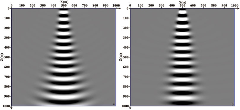
FIGURE 1. Comparison diagram of beam propagation in the constant velocity model. (A) Gaussian beam and (B) Fresnel beam.
The Inverse Fresnel Beam XSP-CDP Stack Imaging
The traditional crosswell seismic reflection XSP-CDP stack imaging method is to transform the sample value of the record in each CSG (or CRG) from the depth-time domain to the reflection point depth-offset domain. Each sample point in CSG can only be converted into one sample point in CRP gather. In this article, the wave field energy of each receiver is derived from the Fresnel beam energy weight of the effective rays in its Fresnel zone. Therefore, based on the Huygens–Fresnel wave field theory, the single channel record in CSG (or CRG) is converted and decomposed into multichannel CRP wave field records in the Fresnel zone under the constraint of the wave theory, and the number of reflection points is adaptively increased to improve the imaging accuracy.
The process of XSP-CDP wave field conversion is similar to NMO correction, that is, each sample point of the CSG is converted to the corresponding CRP gather. In the CSG data, ΔT1 is the travel time difference of the reflection wave from adjacent strata. The XSP-CDP conversion is to convert the wave field of ΔT1 into the wave field of ΔT2 in the adjacent strata of CRP gather, as shown in Figure 2. In order to eliminate the time difference between ΔT1 and ΔT2, ΔT1 is corrected according to the coordinates of reflection points and the depth of strata, and the corresponding wave field is converted into the wave field with the time difference of ΔT2.
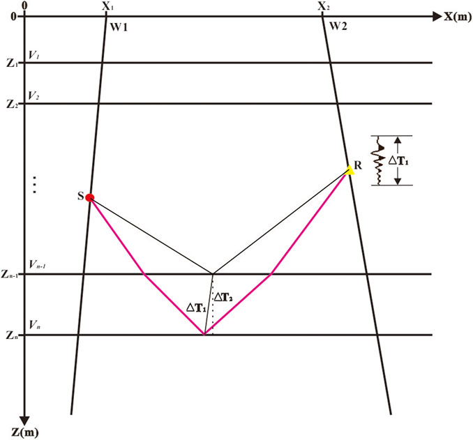
FIGURE 2. Schematic diagram of XSP-CDP wave field conversion.
As shown in Figure 3, TRN is the sample point time when the R-channel receives the reflected wave field from the n-set stratigraphic interface, and ARN is its wave field size. The inverse Fresnel beam XSP-CDP wave field conversion is to migrate the wave field at TRN time into the reflection points belonging to the first Fresnel zone by preserving amplitude. The coordinates and weight functions of the effective rays that contribute to the ARN can be obtained through the wave field forward modeling. If the coordinate of a reflection point is (Xref, Zref), the inverse Fresnel beam XSP-CDP transformation can be expressed as,
where TNMO is the two-way travel time of the reflection point relative to the surface after the inverse Fresnel beam XSP-CDP wave field conversion.
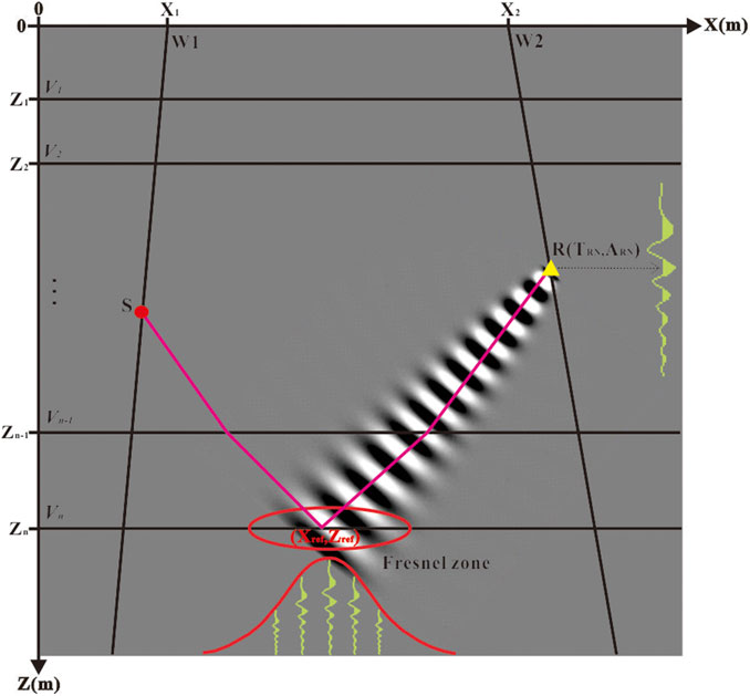
FIGURE 3. Schematic diagram of inverse Fresnel beam XSP-CDP wave field conversion.
The crosswell seismic inverse Fresnel beam XSP-CDP stack imaging calculation steps are as follows: First, the spatial position of CRP, which belongs to the first Fresnel zone corresponding to the receiver point, and its Fresnel beam weight functions are calculated through the Fresnel beam forward modeling method combined with the velocity model established by the first-arrival wave tomography.
The Second step is carried out by calculating the NMO time based on the VSP-CDP conversion idea and migrating the amplitude of input trace to the imaging grid points of the output channel in the first Fresnel zone adaptively. This process decomposes and converts the single trace wave field of CSG (or CRG) into multichannel CRP wave field records in the Fresnel zone under the constraint of the wave theory.
Finally, the bins are divided according to a certain interval (including in X and t directions). If the sample point (x, t) after the inverse Fresnel beam XSP-CDP conversion falls into a CDP bin, then the sample point belongs to the CDP. All samples are migrated as mentioned previously, and the number of samples falling into each bin is counted, and their amplitudes are stacked as the output samples of the CDP point. Until all samples are completed, the final stack imaging profile is obtained.
The workflow of the inverse Fresnel beam XSP-CDP stack imaging method in crosswell seismic is shown in Figure 4.
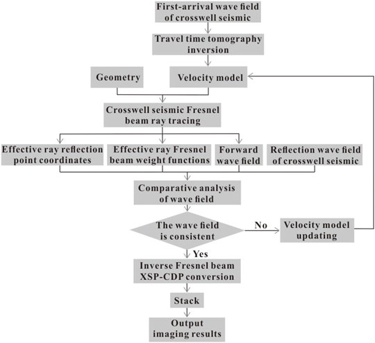
FIGURE 4. Workflow of the inverse Fresnel beam XSP-CDP stack imaging method.
Results
Model Test
Based on the crosswell seismic inverse Fresnel beam stack imaging method, this section will test the correctness and robustness of the method through theoretical data. The parameters of geometry are shown in Table 1. The original field seismic data are shown in Figure 5. It can be seen from the figure that the first-arrival wave energy of the crosswell seismic is prominent and easy to pick up. The constant velocity model is used as the initial velocity (as shown in Figure 6A), and Figure 6B is the result of tomography. The crosswell seismic Fresnel beam forward modeling method is carried out with geometry shown in Table 1 based on the aforementioned velocity model, and the ray path and wave field record diagram are shown in Figure 7. As shown in Figure 7B, the velocity field is checked and optimized by interactively comparing the wave field records of the forward simulation (in red color) with the seismic records collected in the field (in black color). The crosswell seismic inverse Fresnel beam XSP-CDP wave field conversion method is used to image the original seismic data, and the CDP bin is 10 m for stacking. The imaging result is shown in Figure 8. We can see that the crosswell seismic first-arrival wave velocity tomography provides an accurate velocity field for reflection wave imaging. The Fresnel beam forward numerical simulation method not only optimizes the velocity model but also provides the Fresnel beam weight function of the effective ray for the imaging, which makes the fold number of the reflection point more uniform and improves the imaging effect.
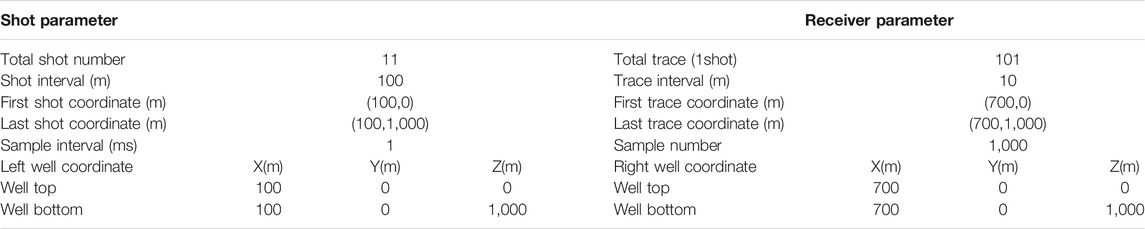
TABLE 1. Geometry parameters.
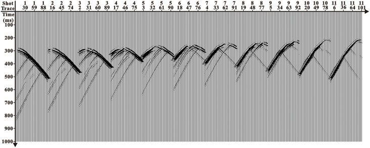
FIGURE 5. Original field seismic data.
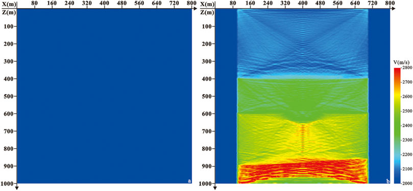
FIGURE 6. Velocity model. (A) Initial velocity model and (B) velocity of first-arrival wave tomography.
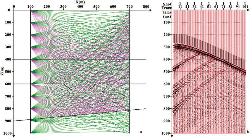
FIGURE 7. Ray path diagram and comparison diagram of wave field interaction. (A) Ray path and (B) wave field interaction comparison diagram of the 1st shot.
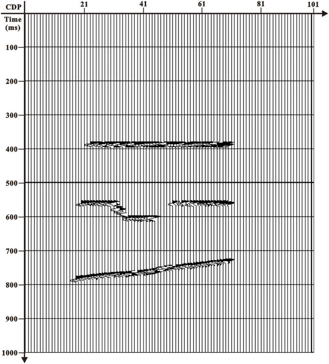
FIGURE 8. Section of crosswell seismic inverse Fresnel beam stack imaging.
Practical Application
This part employs practical data to test the effectiveness of the proposed inverse Fresnel beam stacking method. We apply the method to a crosswell seismic field data in the Bohai oilfield in China. Figure 9 is the imaging section of the ground seismic passing through the wells. Affected by the gas cloud, the internal wave field energy of the imaging section is weak (as shown in the circle in Figure 9), and the event axis is not clear, which is difficult to reflect the structural characteristics of the gas cloud area. Therefore, crosswell seismic exploration is carried out near the gas cloud area. The geometry parameters of crosswell seismic are shown in Table 2, and the original P-wave field record is shown in Figure 10 (the 36th shot after three-component synthesis). The travel time of the first-arrival wave is picked up and used for velocity tomography inversion, and the crosswell velocity model is obtained as shown in Figure 11. The geological model was established based on the results of ground seismic imaging and velocity tomography, and the Fresnel beam wave field numerical simulation of the crosswell seismic was carried out. The ray path and wave field record are shown in Figure 12. Figure 12B is the wave field interaction diagram between the forward modeling seismic records of the 39th shot (in red color) and the field seismic records after wave field separation (in black color). In the actual data processing, the crosswell seismic Fresnel beam forward simulation can not only optimize the velocity field and calculate the Fresnel beam weight function of effective rays but also guide the wave field separation of crosswell seismic. The result of crosswell seismic inverse Fresnel beam stack imaging is shown in Figure 13A. It can be seen that the crosswell seismic imaging results can effectively solve the problem of unclear geological structures in the gas cloud area. As shown in Figure 13B, the crosswell seismic imaging results (CDP bin is 6.25 m) are embedded in the ground seismic imaging profile (CDP bin is 25 m). We can see that the crosswell seismic imaging results effectively compensate for the presence of ground seismic, and the crosswell seismic imaging results outside the gas cloud area are consistent with the ground seismic imaging results.
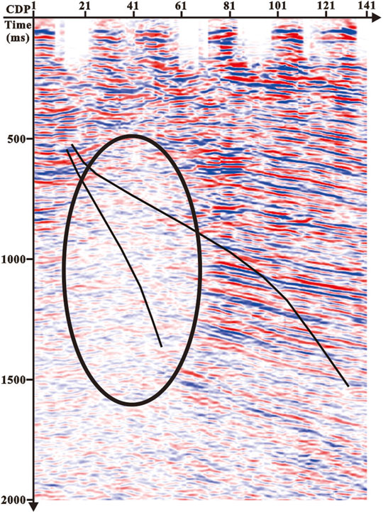
FIGURE 9. Seismic imaging section across the wells.
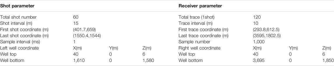
TABLE 2. Geometry parameters.
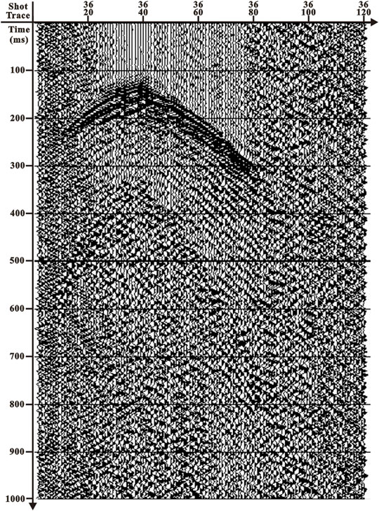
FIGURE 10. Wave field records of crosswell seismic.
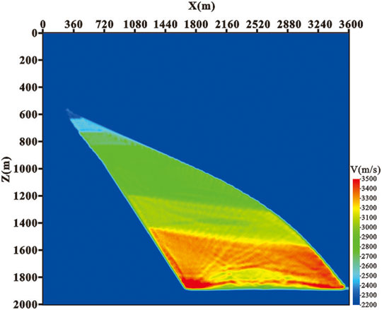
FIGURE 11. Result of first-arrival wave velocity tomography.
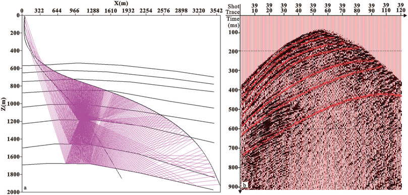
FIGURE 12. Ray path diagram and comparison diagram of wave field interaction. (A) Ray path and (B) wave field interaction comparison diagram.
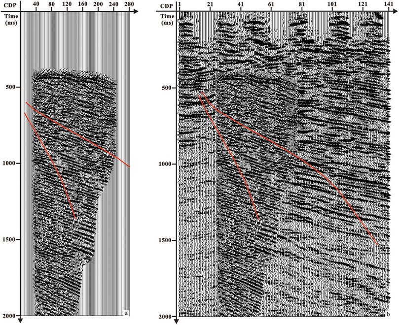
FIGURE 13. Imaging results. (A) Section of crosswell seismic inverse Fresnel beam stack imaging and (B) overlapping map of crosswell seismic and ground seismic imaging.
Discussion
Based on the Huygens–Fresnel wave field propagation theory, an inverse Fresnel beam stack imaging method suitable for crosswell seismic complex structures is proposed. The effectiveness and stability of the proposed method are verified by a theoretical model and practical data example. By studying the properties and characteristics of the Fresnel beam, the weight function formula based on the Fresnel beam stacking is derived, and it is applied to crosswell seismic stack imaging, which adaptively increases the fold number of the reflection point and improves the lateral resolution of seismic imaging. The results of model calculation and actual data processing show that this method can finely image crosswell seismic data and effectively improve the lateral resolution of imaging. It has a potential value to become one of the effective tools for crosswell seismic wave field imaging.
Data Availability Statement
The original contributions presented in the study are included in the article/Supplementary Material, further inquiries can be directed to the corresponding author.
Author Contributions
F-LY, G-YR, F-MY, and CZ contributed to the conception and design of the study. F-LY deduced the algorithm and implemented the core algorithm of this manuscript. G-YR carried out the main work in the establishment of the theoretical model. The theoretical model is used to verify the correctness of the proposed method. F-MY and CZ have performed great work in practical data collation and trial calculations. All authors contributed to manuscript revision and read and approved the submitted version.
Funding
This work was funded by the Open Fund (PLC. 20211106) of State Key Laboratory of Oil and Gas Reservoir Geology and Exploitation (Chengdu University of Technology) and the Natural Science Basic Research Plan in Shaanxi Province of China (grant no. 2021JQ-588).
Conflict of Interest
The authors declare that the research was conducted in the absence of any commercial or financial relationships that could be construed as a potential conflict of interest.
Publisher’s Note
All claims expressed in this article are solely those of the authors and do not necessarily represent those of their affiliated organizations, or those of the publisher, the editors, and the reviewers. Any product that may be evaluated in this article, or claim that may be made by its manufacturer, is not guaranteed or endorsed by the publisher.
References
Buske, S., Gutjahr, S., and Sick, C. (2009). Fresnel Volume Migration of Single-Component Seismic Data. Geophysics 74 (6), WCA47–WCA55. doi:10.1190/1.3223187
Cai, Z. (2021). Borehole Seismic: A Bridge Connecting Multiple Oil and Gas Exploration Methods. Oil Geophys. Prospecting 56 (4), 922–934. doi:10.13810/j.cnki.issn.1000-7210.2021.04.025
Cai, Z., Yang, B., and Wang, Y. (2022). Application of Optical Fiber Bore Hole Seismic Technology in Western China. Geophys. Prospecting Pet. 61 (1), 122–131. doi:10.3969/j.issn.1000-1441.2022.01.013
Červený, V., and Pšenčík, I. (1984). Gaussian Beams in Elastic 2-D Laterally Varying Layered Structures. Geophys. J. Int. 78, 65–91. doi:10.1111/j.1365-246X.1984.tb06472.x
Chauris, H., and Salomons, B. (2004). “Seismic Applications of One-Way Acoustic Reciprocity,” in Proceedings of the 66th Annual International Conference and Exhibition, Paris, France, 7-11 June, 2004 (Houten, Netherlands: EAGE), G026. Extended Abstracts.
Gao, F., Zhang, P., Wang, B., and Dirks, V. (2006). “Fast Beam Migration - A Step toward Interactive Imaging,” in Proceedings of the 76th Annual International Meeting, New Orleans, Louisiana, 1-6 October 2006 (Tulsa, Oklahoma, United States: SEG), 2470–2474. Expanded Abstracts. doi:10.1190/1.2370032
Gray, S. H., and Bleistein, N. (2009). True-amplitude Gaussian-Beam Migration. Geophysics 74 (2), S11–S23. doi:10.1190/1.3052116
Gray, S. H. (2005). Gaussian Beam Migration of Common-Shot Records. Geophysics 70 (4), S71–S77. doi:10.1190/1.1988186
Hale, D. (1992). “Migration by the Kirchhoff, Slant Stack, and Gaussian Beam Methods,” Report 121 (Golden, Colorado: Colorado School of Mines, Center for wave phenomena).
Han, B., Gu, H., Liu, S., Yan, Z., Tang, Y., and Liu, C. (2018). Wavelength-dependent Fresnel Beam Propagator and Migration in VTI media. J. Appl. Geophys. 155, 176–186. doi:10.1016/j.jappgeo.2018.06.010
Hill, N. R. (2001). Prestack Gaussian‐beam Depth Migration. Geophysics 66, 1240–1250. doi:10.1190/1.1487071
Hu, C., and Stoffa, P. L. (2009). Slowness-driven Gaussian-Beam Prestack Depth Migration for Low-fold Seismic Data. Geophysics 74 (6), WCA35–WCA45. doi:10.1190/1.3250268
Hua, B. L., and McMechan, G. A. (2001). Parsimonious 2‐D Poststack Kirchhoff Depth Migration. Geophysics 66, 1497–1503. doi:10.1190/1.1487095
Hua, B., and McMechan, G. A. (2003). Parsimonious 2D Prestack Kirchhoff Depth Migration. Geophysics 68, 1043–1051. doi:10.1190/1.1581075
Huang, J., Yang, J., Liao, W., Wang, X., and Li, Z. (2016). Common-shot Fresnel Beam Migration Based on Wave-Field Approximation in Effective Vicinity under Complex Topographic Conditions. Geophys. Prospecting 64, 554–570. doi:10.1111/1365-2478.12276
Kong, Q., Wang, Y., Jianjun, Z., Guohua, W., and Hongquan, W. (2007). Study and Application of Finite Angle Stack Approachincross-Hole Seismology. Oil Geophys. Prospecting 42 (3), 256–262. doi:10.3321/j.issn:1000-7210.2007.03.004
Koren, Z., Ravve, I., Ragoza, E., Bartana, A., Geophysical, P., and Kosloff, D. (2008). “Full‐azimuth Angle Domain Imaging,” in Proceedings of the 78th Annual International Meeting, Las Vegas, Nevada, 9-14 November 2008 (Tulsa, Oklahoma, United States: SEG), 2221–2225. Expanded Abstracts. doi:10.1190/1.3059327
Li, H., and Qiang, N. (2016). Forward Simulation Method for Crosswell Seismic of 3D Block Forward Modeling. Pet. Geology. Eng. 30 (3), 17–20. doi:10.3969/j.issn.1673-8217.2016.03.005
Ma, G., Cao, D., Yin, J., and Zhu, Z. (2020). Numerical Simulation of Detecting Seismic Signals in DAS wells. Oil Geophys. Prospecting 55 (2), 311–320. doi:10.13810/j.cnki.issn.1000-7210.2020.02.012
Nowack, R. L. (2008). “Focused Gaussian Beams for Seismic Imaging,” in Proceedings of the 78th Annual International Meeting, Las Vegas, Nevada, 9–14 November 2008 (Tulsa, Oklahoma, United States: SEG), 2376–2380. Expanded Abstracts. doi:10.1190/1.3059356
Nowack, R. L., Sen, M. K., and Stoffa, P. L. (2003). “Gaussian Beam Migration for Sparse Common‐shot and Common‐receiver Data,” in Proceedings of the 75th Annual International Meeting, The Breakers Hotel, September 16-21, 2003 (Tulsa, Oklahoma, United States: SEG), 1114–1117. Expanded Abstracts. doi:10.1190/1.1817470
Sun, H., and Schuster, G. T. (2001). 2‐D Wavepath Migration. Geophysics 66, 1528–1537. doi:10.1190/1.1487099
Sun, H., and Schuster, G. T. (2003). 3D Wavepath Migration. Geophys. Prospecting 51, 421–430. doi:10.1046/j.1365-2478.2003.00380.x
Wang, X., and Yang, J. (2015). “Prestack Depth Migration Using Adaptive Focused Beams,” in Proceedings of the 85th Annual International Meeting, New Orleans, Louisiana, USA, 18-23 October 2015 (Tulsa, Oklahoma, United States: SEG), 4293–4297. Expanded Abstracts. doi:10.1190/segam2015-5801751.1
Wyatt, K. D. (1981). Synthetic Vertical Seismic Profile. Geophysics 46 (6), 880–891. doi:10.1190/1.1441227
Yan, Y., Yi, M., Xin, W., and Wan, W. (2000). The Imaging and Interpretation of Reflection Waves in Cross-Hole Seismic Data. Oil Geophys. Prospecting 35 (1), 36–41. doi:10.13810/j.cnki.issn.1000-7210.2000.01.006
Yang, F., Li, H., Sun, H., Zhang, X., Luo, H., and Zhao, C. (2020b). VSP-CDP Stack Imaging Based on the Weight Function of normal Distribution. Oil Geophys. Prospecting 55 (1), 101–110. doi:10.13810/j.cnki.issn.1000-7210.2020.01.012
Yang, F., Sun, Y., Lu, J., Ma, D., Jing, Y., and Pei, D. (2015). The Gaussian Beam Stack Imaging Method of VSP[J]. Geophys. Geochemical Exploration 39 (3), 627–632. doi:10.11720/wtyht.2015.3.33
Yang, F., Zhao, C., Zhengrong, W., Sun, H., Li, H., Zhao, C., et al. (2020a). A Research on Inverse Gaussian Beam Stack Imaging in 3D Crosswell Seismic of Deviated Well and its Application[J]. Appl. Geophys. 17 (5), 629–638. doi:10.1007/s11770-019-0830-x
Yang, F., Zhengrong, W., and Li, Q. (2016). “The Inverse Gaussian Beam Common-Reflection-point Stack Imaging in Crosswell Seismic[C],” in The 86th SEG Technical Program, Dallas, Texas, USA, 16-21 October 2016 (Tulsa, Oklahoma, United States: SEG), 840–845. Expanded Abstracts. doi:10.11720/wtyht.2015.3.33
Yang, J.-D., Huang, J.-P., Wang, X., and Li, Z.-C. (2015a). An Amplitude-Preserved Adaptive Focused Beam Seismic Migration Method. Pet. Sci. 12, 417–427. doi:10.1007/s12182-015-0044-7
Yang, J. D., Huang, J. P., Wang, X., and Li, Z. C. (2015c). “Fresnel Beam Depth Migration from the Irregular Topography,” in Proceedings of the 85th Annual International Meeting, New Orleans, Louisiana, USA, 18-23 October 2015 (Tulsa, Oklahoma, United States: SEG), 4318–4322. Expanded Abstracts. doi:10.1190/segam2015-5747594.1
Yang, J. (2016). The Research of Seismic Beam Migration Limited by Dynamic Parameters. Beijing, China: School of Geosciences China University of Petroleum.
Yue, Y., Li, Z., Qian, Z., Zhang, J., Sun, P., and Ma, G. (2012). Amplitude-preserved Gaussian Beam Migration under Complex Topographic Conditions. Chin. J. Geophys. 55, 1376–1383. doi:10.6038/j.issn.0001-5733.2012.04.033
Yue, Y., Qian, Z., Zhang, X., Wang, D., Yue, Y., and Chang, W. (2019a). Gaussian Beam Based Born Modeling Method for Single-Scattering Waves in Acoustic Medium. Chin. J. Geophys. 62, 648–656. doi:10.6038/cjg2019M0367
Yue, Y., Sava, P., Qian, Z., Yang, J., and Zou, Z. (2019c). Least-squares Gaussian Beam Migration in Elastic media. Geophysics 84 (4), S329–S340. doi:10.1190/geo2018-0391.1
Yue, Y., Sun, P., Wang, D., Sun, P., Guo, Z., and Liu, Z. (2019b). Gaussian Beam Based Modeling Method for Single-Scattering Waves in Elastic Isotropic Medium. Chin. J. Geophys. 62, 657–666. doi:10.6038/cjg2019M0396
Zhao, B., Dong, S., and Zeng, Z. (2017). Borehole Seismic Development, Status Quo and Future: Application prospect of Borehole Seismic. Oil Geophys. Prospecting 52 (5), 1112–1123. doi:10.13810/j.cnki.issn.1000-7210.2017.05.026
Keywords: crosswell seismic, inverse Fresnel beam, weight function, tomography, stack imaging
Citation: Yang F-L, Ren G-Y, Yao F-M and Zhao C (2022) The Inverse Fresnel Beam XSP-CDP Stack Imaging in Crosswell Seismic. Front. Earth Sci. 10:851379. doi: 10.3389/feart.2022.851379
Received: 09 January 2022; Accepted: 28 February 2022;
Published: 28 March 2022.
Edited by:
Jidong Yang, China University of Petroleum, ChinaCopyright © 2022 Yang, Ren, Yao and Zhao. This is an open-access article distributed under the terms of the Creative Commons Attribution License (CC BY). The use, distribution or reproduction in other forums is permitted, provided the original author(s) and the copyright owner(s) are credited and that the original publication in this journal is cited, in accordance with accepted academic practice. No use, distribution or reproduction is permitted which does not comply with these terms.
*Correspondence: Fei-Long Yang, ZmVpbG9uZ3lAeHN5dS5lZHUuY24=