- 1Key Laboratory of Geotechnical Mechanics and Engineering of Ministry of Water Resources, Changjiang River Scientific Reseatch Institute, Wuhan, China
- 2Institute of Rock and Soil Mechanics, Chinese Academy of Sciences, Wuhan, China
- 3State Key Laboratory of Geomechanics and Geotechnical Engineering, University of Chinese Academy of Sciences, Beijing, China
- 4Hydropower Engineering Institute, Power China Huadong Engineering Corporation Limited, Hangzhou, China
The umbrella-shaped bolt (U-bolt) is a novel type of mechanical bolt used for rock reinforcement. It is made of a smooth steel bar, hinges, rigid rods, and sliding blocks. During installation and operation, the tension of the bolt is converted into the extrusion force on the rock mass deep in slope, so that the higher compressive strength of the rock mass is used to obtain the greater friction force and anchoring force. In this article, the structural and mechanical analysis results of the U-bolt is provided, and the relation between penetration and point normal stress is discussed. Based on these analyses, a simulation method for the U-bolt is proposed. The bolt elements are identified at first, then the penetration on the rock mass is calculated, and the tensile strength of bolt elements is increased to a reasonable value. Meanwhile, the method is applied to deep-buried rock reinforcement and a rock slope, and simulation results reveal that the U-bolt can alleviate the fracturing degree and reduce the depth and displacement of the excavation damaged zone (EDZ), and decrease the landslide distance.
1 Introduction
The sustainability of underground caves (such as tunnels and caves) is mainly determined by three factors: rock quality, in situ stress, and the size or geometry of the cave (Li, 2012). The stress of shallow rock engineering is usually low, and the main stability problem is that the rock falls under gravity (Bizjak and Petkovšek, 2004). In the case of deep-buried hard rock engineering, the rock mass is usually hard and brittle, and the tensile failure should be the main mechanism (Su et al., 2017). In general, the loosened rock blocks or fractured rock mass can be stabilized by installing internal support devices like rock bolts (Cai et al., 2004). Therefore, the bearing capacity of the bolt is a crucial parameter in rock engineering (Chen, 2014).
Meanwhile, a rock slope is also a common kind of rock engineering. Its failure mechanisms and stability have been continuously investigated by researchers in ways of numerical methods, limit equilibrium methods (Aydan and Kawamoto, 1992; Zheng et al., 2018), and other new methods (Zheng et al., 2021). Swelling prestressed bolts and its use in the mechanized excavation of large-section tunnels (Liu et al., 2018), and also prestressed hollow grouting anchor rock burst prevention tunnel design (Wang and He, 2011). To strengthen the stability of rock slopes, using rock bolts is a common measure, such as grouting bolt, mechanical shell-expanding bolt, and other new types of bolts. These rock bolts mentioned before have solved engineering problems faced in the process of tunnel construction.
Numerous studies have been carried out on rock bolts, and various types of bolts with high load capacity and high deformation capacity have been successfully developed and applied, such as cone bolts, Garford bolts, and D-bolts. The cone bolt is the first energy-absorbing-type bolts, and its rejuvenated anchor consists of a smooth steel rod with a flat, running flame forged at the distal end (Li et al., 2014), which can withstand significant deformation of the rock mass by allowing the rejuvenated anchor to move in the grouting materials such as the mortar and the resin. The Garford bolt developed in Australia consists of smooth reinforcement, unique technical anchor, and steel hull at the distal end of the anchor (Varden et al., 2008; Li et al., 2014), in which the inner diameter of the anchor is smaller than that of the bar inside the sleeve. After the rock is deformed, the bolt starts extruding from the inner hole of the bolt, absorbing the enormous energy generated by the expansion of the rock. The D-bolt developed in Norway consists of a smooth steel rod and several bolts used in the deep construction to prevent the tunnel from collapsing because of the rock burst. The D-bolt can achieve both high loading capacity and deformability by the elongation of the steel bar between anchors (Li, 2010; Li et al., 2014). These energy-absorbing bolts are considered as important support materials for rock breaking and for the crushing of soil treasures in underground construction. Generally speaking, these energy-absorbing rock bolts are considered as important support materials for rock fracturing and fragmentation.
In this study, a novel umbrella-shaped bolt (U-bolt) was proposed. It is mainly composed of hinges and rigid rods and uses the compression and friction to obtain the anchoring force. The new bolt is introduced in Section 2, concentrating on the structural and mechanical analyses of U-bolts, and the relation between penetration and point normal stress was discussed. The numerical model establishment method for U-bolts was described in Section 3. This method was then applied to the U-bolt simulation of the rock tunnel excavation and rock slope in Section 4, and the performance of U-bolts was compared between no supporting and U-bolt-supporting cases.
2 Structural Analysis
2.1 Basic Description of Umbrella-Shaped Bolt
As shown in Figure 1A, the umbrella-shaped bolt consists of the top hinge, the rigid rod, the linking rod, the anchoring tray, the bottom sliding block, the main bolt, the middle sliding block, and the middle hinge. Many rigid rods are connected to the main bolt through the top hinge, and they are also connected with the corresponding linking rods with the middle hinge. The linking rod can move with the middle sliding block along the main bolt. In addition, there is also a bottom sliding block adhering to the anchoring tray. The bolt in the packing state (Figure 1B) and opening state (Figure 1C) is also illustrated.
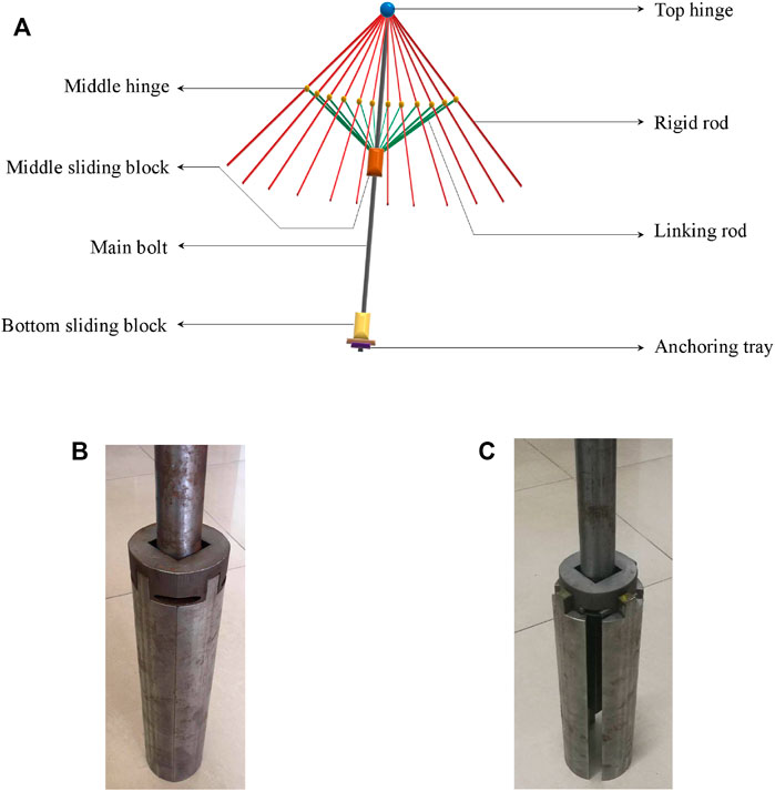
FIGURE 1. Umbrella-shaped bolt, in which (A) the sketch figure, (B) bolt image in packing state, and (C) bolt image in opening state.
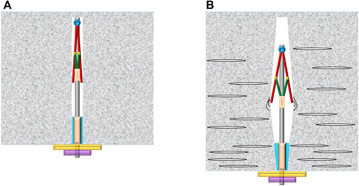
During installation (as illustrated in Figure 2A), a bore hole with a reasonable dimension is drilled at first and the U-bolt is then inserted into the hole of the rock mass. Both the rigid rods and linking rods shrink together, which are close to the main bolt in this process. The bottom sliding block is adhered to the rock mass with glue, and the anchoring tray is fixed on the surface of the internal tunnel free face.
When the rock mass initiates dilation with many excavation-induced fractures (as shown in Figure 2B), the whole section begins to expand (Wang et al., 2020). The main bolt then starts to extend, and the rigid rods initiate expanding. They squeeze the internal face of the bore hole, and friction emerges between the internal face and the rigid rod. This friction and the tensile strength inhibit the dilation of the rock mass. Generally speaking, the tension of the bolt is converted into the extrusion force on the rock mass, and the higher the compressive strength of the rock mass is, the greater the friction force and anchoring force the bolt can obtain.
2.2 Force Analysis
The mechanical analysis is studied in this section. As shown in Figure 3A, when the U-bolt is totally expanding, we define the distance between the top and middle hinges as width w, and the distance between the top hinge and the end of the rigid rod as distance d. The angle between the main bolt and the linking rod is
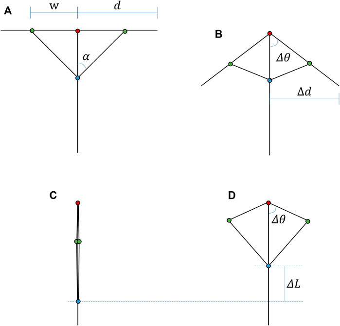
FIGURE 3. Geometry structure of the U-bolt, where (A) the structure when U-bolt is totally expanding, (B) the structure when U-bolt is working, (C) the structure when U-bolt is installing, and (D) geometry shape of main bolt, rigid rod, and linking rod.
As illustrated in Figure 3B, when the U-bolt is working, the opening angle is defined as
In Figure 3C, we can find that the initial position distance between the top hinge and middle sliding block can be obtained as follows:
The law of cosines (Lee, 1997) will be satisfied (as shown in Figure 3D), and the relation between the opening angle
In the reasonable range of
When the U-bolt is working (Figure 4A), the additional tensile stress is provided with two parts, including the tensile strength
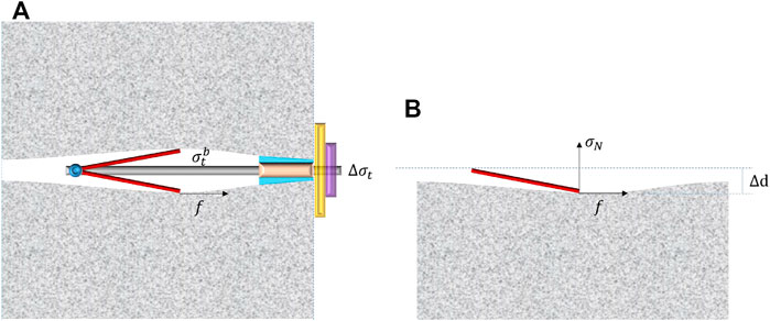
FIGURE 4. Force analysis of the U-bolt, where (A) all forces and (B) the force on the internal surface of bore hole.
As illustrated in Figure 4B, the friction can be calculated according to the Coulomb criterion (Renard, 2006), which means that
where
The expanding length
where
2.3 Relation Between Penetration and Point Normal Stress
As pointed out in Eq. 8, in order to study the relation between the penetration and the point normal stress, it is better to establish the relation between the stiffness and the penetration in Eq. 8. Here, a numerical approach is provided, and the analysis zone is considered as an elastic body.
As illustrated in Figure 5, four simulation grids are set, including 0.5 mm (Figure 5A), 1 mm (Figure 5B), 2.5 mm (Figure 5C), and 5 mm (Figure 5D). The size of all these four grids is 0.5 mm × 0.1 mm, and the aspect ratios are all 2 to eliminate the influence of the aspect ratio effect. The bottom edge of these simulation specimens is fixed at the vertical direction, and the middle of the bottom edge is also fixed at the horizontal direction. Only the middle of the top edge is vertical displacement loading representing the point loading.
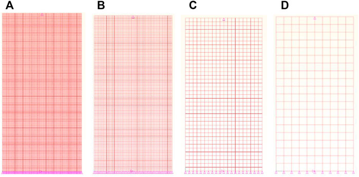
FIGURE 5. Four grids to study the relation between penetration and point normal stress, in which the element size is set as (A) 0.5 mm, (B) 1 mm, (C) 2.5 mm, and (D) 5 mm.
At least 18 simulation tests were conducted for each grid, and the mechanical properties are listed in Table 1. It should be noted that 45 tests were conducted for 0.05 mm element size, and 18 tests (Nos. 1∼18 in Table 1) were conducted for other element sizes.
A fitting function between the normal stiffness
where

TABLE 2. Fitting coefficients and R square of the relation between the normal stiffness
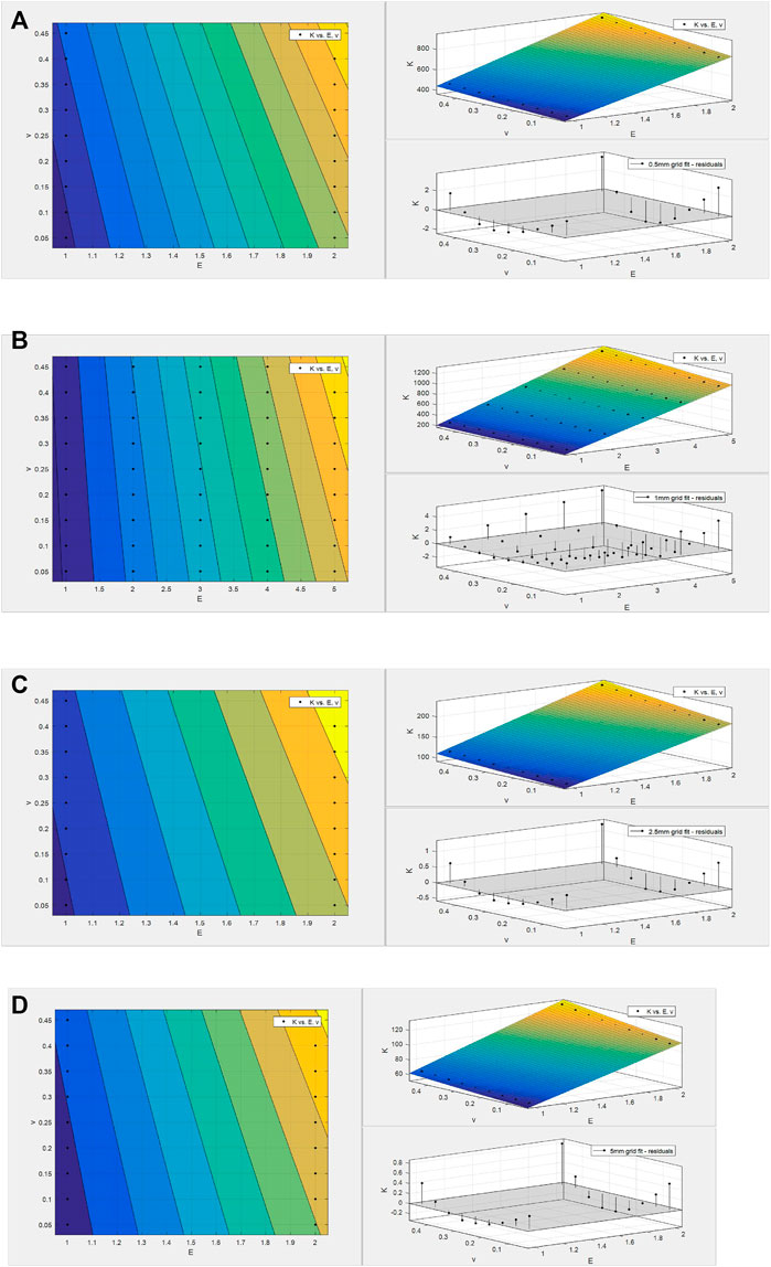
FIGURE 6. Fitting results of stiffness K against the elastic modulus E and Poisson’s ratio v, in which the element size is (A) 0.5 mm, (B) 1 mm, (C) 2.5 mm, and (D) 5 mm.
The element size effect is also considered, an exponent function is proposed, and the following relation is obtained:
where
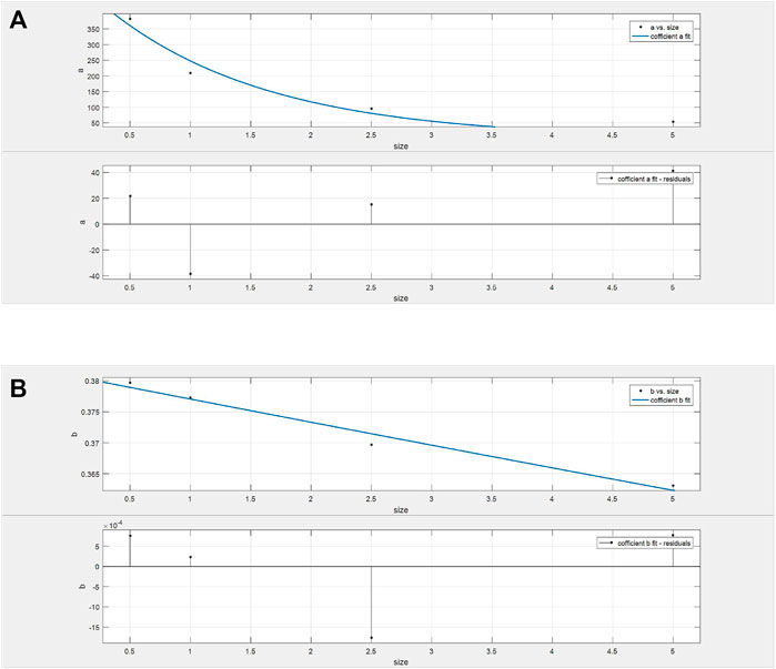
FIGURE 7. Fitting results of coefficients against element sizes, where (A) coefficient
Combing all these equations, the enhanced tensile strength provided by the U-bolt can be calculated as follows:
In Eq. 11, there are only 8 parameters that need to be determined, of which
3 Numerical Implementation
3.1 Basic Framework
The numerical implementation of the U-bolt follows a simple framework, which is finding the element where bolts go through (they are defined as the bolt elements), then calculating the enhanced tensile strength based on the extension length
3.2 Identification of Bolt Elements
The bolt elements are identified at the beginning of the simulation. There are three cases that emerge during the identification of bolt elements, as shown in Figure 8, including case A where the bolt does not go through any node of the bolt element, case B where the bolt goes through 1 node of the bolt element, and case C where the bolt goes through 2 nodes of the bolt element.
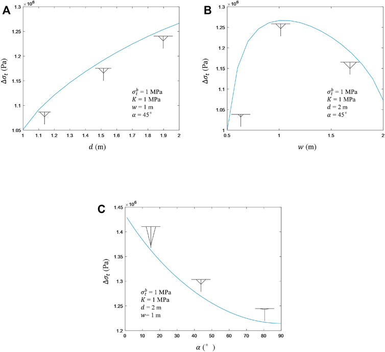
FIGURE 8. Sensibility analysis of the structural parameters d, w, and α. (A), (B), and (C) are the influences of
For cases A and B, it is easy to point out the bolt element through elements where the bolt cut across. For case C, it may be a little different, in which the 2 elements with opposite positions where the bolt goes through are all treated as the bolt elements.
3.3 Calculation of the Penetration
Figure 9 shows two moments of the U-bolt operation in the simulation. For Figure 9A, when the bolt is installed, the initial length of the U-bolt will be calculated using the following equation:
where
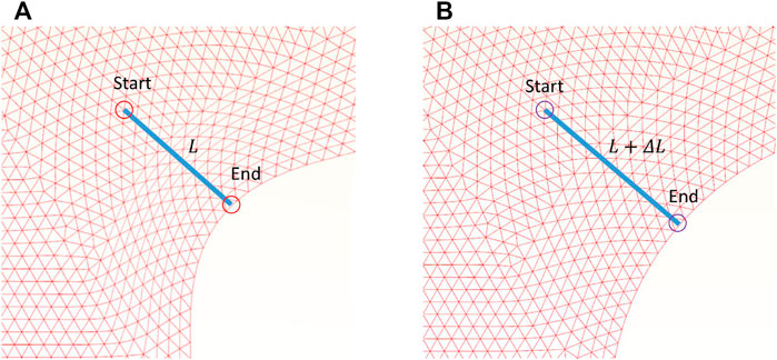
FIGURE 9. Calculation of the penetration, in which (A) the moment when U-bolt installs, and (B) the moment when U-bolt is working.
Using Eqs 12, 13, the current length of the U-bolt
3.4 Tensile Strength Reinforcement of Bolt Elements
Once the extension length
4 Application in Rock Engineering
4.1 Case 1: Rock Tunnel Excavation
4.1.1 Simulation Preparation
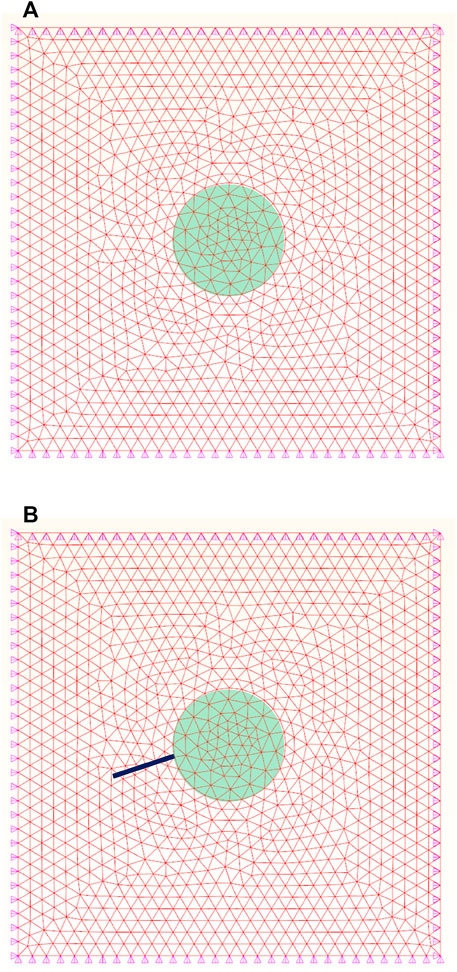
Figure 10 provides the simulation setup of the rock tunnel excavation. Figure 10A is the no supporting case, and Figure 10B is the case with U-bolt supporting. The size is set to be 60 m
The crustal stress information is shown in Table 3, the rock mass properties are listed in Table 4, and the U-bolt parameters are provided in Table 5. The cohesion-weakening and friction-strengthening (CWFS) model is chosen as the constitutive model (Hajiabdolmajid et al., 2002; Feng et al., 2021). It should be noted that the U-bolt length and corresponding strength are set to be long and strong in order to make results more evident.
4.1.2 Performance of Umbrella-Shaped Bolts
The equivalent plastic strain (Hajiabdolmajid and Kaiser, 2003; Faleskog and Barsoum, 2013) can be applied to reflect the failure degree and the depth of excavation damaged zone. Figure 11 shows the simulated equivalent plastic strain results of two cases. For the no support case (Figure 11A), the bottom left part seems to be symmetrical to the top right part, and the equivalent plastic strain for the most seriously damaged area is about 0.005.
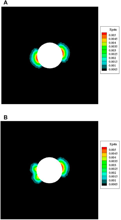
FIGURE 11. Simulated equivalent plastic strain results, in which (A) no support and (B) support with U-bolt.
For the U-bolt support case (Figure 11B), the equivalent plastic strain result is not symmetrical for the bottom left part and the top right part. Regarding the bottom left part, the shape of EDZ sank to the tunnel-free face and the depth of EDZ became smaller. Meanwhile, the equivalent plastic strain for the most seriously damaged area in the bottom left part is about 0.004.
Figure 12 compares the displacement evolution results along the bolt direction for no support and support with U-bolt cases. The tangential displacement along the bolt direction for the U-bolt supporting case is significantly inhibited. It changes from about 1 cm for the no support case to about 2 mm for the U-bolt-supporting cases, reducing about 80%. Moreover, the displacement along the bolt direction becomes gentler than that in the fluctuant circumstance of the no support case, indicating the U-bolt makes the rock mass deform globally and entirely.
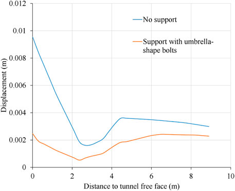
FIGURE 12. Comparison of the displacement evolution results along the bolt direction for no support and support with U-bolt cases. In addition, the result is the displacement plotted against the distance to tunnel-free face.
4.2 Case 2: Rock Slope
4.2.1 Simulating Preparation
Figure 13 illustrates the simulation setup of the rock slope. As shown in Figure 13A, the size is set to be 100 m
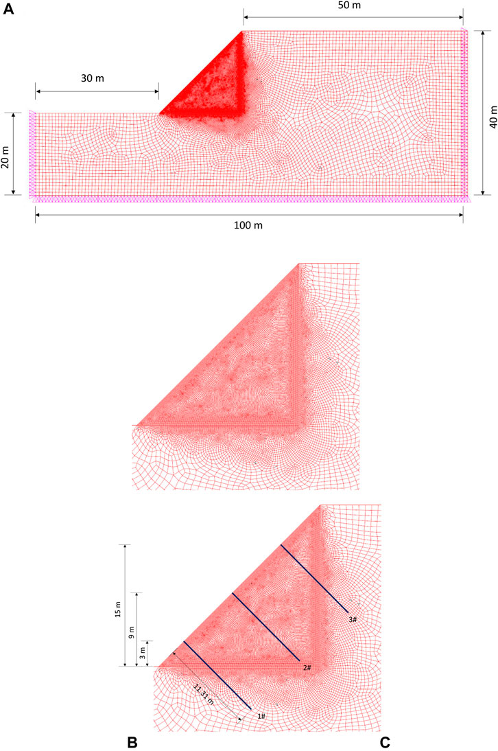
FIGURE 13. Simulation setup of the rock slope, where (A) the simulation mesh and boundary set, (B) no support model, and (C) support model with U-bolt.
Three kinds of U-bolts are set, including 1# (3 m vertical distance from the slope feet), 2# (9 m vertical distance from the slope feet), and 3# (15 m vertical distance from the slope feet). In addition, four simulation cases are conducted: no support case, support case with 1# U-bolt, support case with 1# and 2# U-bolts, and support case with 1#, 2#, and 3# U-bolts. The rock mass properties are given in Table 6, and the U-bolt parameters are provided in Table 5. Furthermore, the CWFS model is used.
4.2.2 Performance of Umbrella-Shaped Bolts
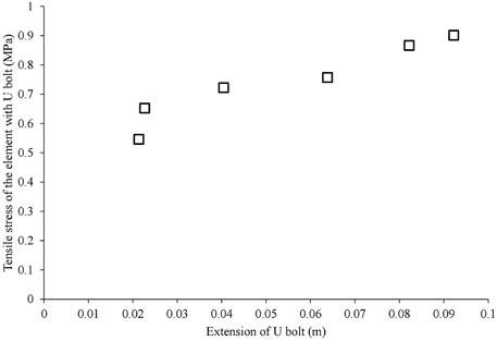
The maximum principal stress contours for all four cases are shown in Figure 14. The tensile stresses on elements with U-bolts are definite for all supporting cases (Figures 14B–D) comparing the no support one (Figure 14A). It indicates that the U-bolt can provide a tensile anchorage force constraining the landslide distance. Another finding of the tensile anchorage stress is illustrated in Figure 15. With the increase in the U-bolt extension, the tensile stresses of element with U-bolt increase, which matches with the basic design of U-bolts in Section 2.1 and operation description Figure 2.
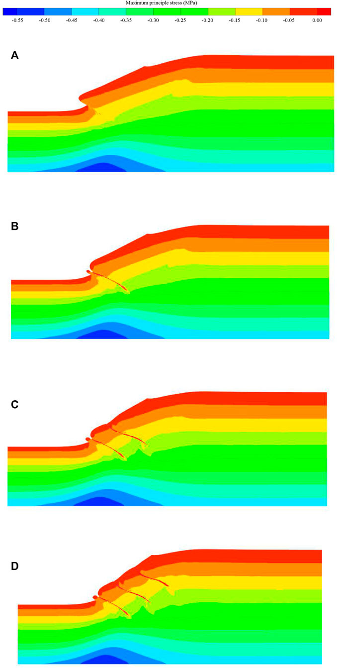
FIGURE 14. Maximum principle stress contours, in which (A) no support, (B) support with 1# U-bolt, (C) support with 1# and 2# U-bolts, and (D) support with 1#, 2#, and 3# U-bolts.
The displacement contours of four simulation cases are shown in Figure 16. For the no support case in Figure 16A, the maximum displacement is larger than 0.07 m, and the sliding volume (here, it is considered as an area whose displacement is greater than 0.03 m in the dashed area in Figure 16) is large. For the support case with 1# U-bolt in Figure 16B, the maximum displacement is about 0.06 m. For the support case with 1# and 2# U-bolts (Figure 16C) and support case with 1#, 2#, and 3# U-bolts (Figure 16D), the maximum displacement is about 0.05 m. Results indicate that the U-bolts can decrease the maximum displacement and sliding volume efficiently.
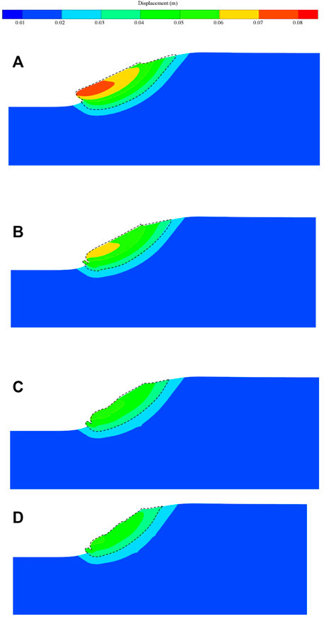
FIGURE 16. Displacement contours, in which (A) no support, (B) support with 1# U-bolt, (C) support with 1# and 2# U-bolts, and (D) support with 1#, 2#, and 3# U-bolts.
Moreover, the slope boundary comparisons of different simulation cases are illustrated in Figure 17. It can be observed that the local constraining effect is evident, especially for 1# U-bolt near the slope feet, as local troughs emerge for the slope boundary. For the green dashed line (support case with 1#, 2#, and 3# U-bolts), the global constraining effect is prominent since the existence of 1#, 2#, and 3# U-bolts. Generally, due to the existence of the U-bolt, the decrease in the landslide distance is evident, and the global anchoring effect becomes better and better with the increase in the U-bolt number.
5 Conclusions and Discussions
A novel type of rock bolt, that is, the U-bolt was proposed in this study. The basic information was introduced at first, and the mechanical analysis was conducted to study the U-bolt reinforcement mechanism. In order to verify the real performance of the U-bolt, a numerical model has been established and then it was applied to the rock tunnel excavation simulation. Results reveal the rationality of the initial design goal of the U-bolt. Some important conclusions can be drawn as follows:
1) This friction and the tensile strength of the U-bolt will inhibit the dilation of the rock mass. The operating mechanism is that the tension of the bolt is converted into the extrusion force on the rock mass, which makes the U-bolt different from other rock bolts. Meanwhile, based on the characteristics of the U-bolt, the bolt can continuously compress the rock mass, and the higher compressive strength of the rock mass is used to obtain the greater friction force and anchoring force.
2) A mechanical model of U-bolt was proposed, and it concentrated on the enhanced tensile strength calculation method on the basis of structural analysis and the relation between penetration and point normal stress.
3) The proposed U-bolt mechanical model has been implemented through the identification of bolt elements, the calculation of the penetration, and the tensile strength reinforcement of bolt elements. The rock tunnel excavation simulations reveal that the U-bolt can reduce the tangential displacement along the bolt and EDZ depth, and alleviate the failure degree. Moreover, the U-bolt can also decrease the landslide distance by providing adequate anchorage force and stress with the extension.
Data Availability Statement
The original contributions presented in the study are included in the article/supplementary material, further inquiries can be directed to the corresponding author.
Author Contributions
YX: conceptualization and methodology; HC: data curation and writing—original draft preparation; YC: writing—review and editing, and project administration; SH: supervision; ZW: software and visualization; and YG: formal analysis.
Funding
The authors sincerely acknowledge the financial support from the National key R&D projects of China (grant No. 2017YFC1501303) and the Fundamental Research Funds for Central Public Welfare Research Institutes (grant No. CKSF2021460/YT).
Conflict of Interest
Author YG was employed by company PowerChina Huadong Engineering Corporation Limited.
The remaining authors declare that the research was conducted in the absence of any commercial or financial relationships that could be construed as a potential conflict of interest.
Publisher’s Note
All claims expressed in this article are solely those of the authors and do not necessarily represent those of their affiliated organizations, or those of the publisher, the editors, and the reviewers. Any product that may be evaluated in this article, or claim that may be made by its manufacturer, is not guaranteed or endorsed by the publisher.
Acknowledgments
The authors express their gratitude to the State Key Laboratory of Geomechanics and Geotechnical Engineering, Institute of Rock and Soil Mechanics, Chinese Academy of Sciences.
References
Aydan, Ö., and Kawamoto, T. (1992). The Stability of Slopes and Underground Openings against Flexural Toppling and Their Stabilisation. Rock Mech. Rock Engng 25 (3), 143–165. doi:10.1007/bf01019709
Bizjak, K. F., and Petkovšek, B. (2004). Displacement Analysis of Tunnel Support in Soft Rock Around a Shallow Highway Tunnel at Golovec. Eng. Geology. 75 (1), 89–106. doi:10.1016/j.enggeo.2004.05.003
Cai, Y., Esaki, T., and Jiang, Y. (2004). A Rock Bolt and Rock Mass Interaction Model. Int. J. Rock Mech. Mining Sci. 41 (7), 1055–1067. doi:10.1016/j.ijrmms.2004.04.005
Chen, Y. (2014). Experimental Study and Stress Analysis of Rock Bolt anchorage Performance. J. Rock Mech. Geotechnical Eng. 6 (5), 428–437. doi:10.1016/j.jrmge.2014.06.002
Faleskog, J., and Barsoum, I. (2013). Tension–torsion Fracture Experiments—Part I: Experiments and a Procedure to Evaluate the Equivalent Plastic Strain. Int. J. Sol. Structures 50 (25-26), 4241–4257. doi:10.1016/j.ijsolstr.2013.08.029
Feng, X. T., Wang, Z., Zhou, Y., Yang, C., Pan, P. Z., and Kong, R. (2021). Modelling Three-Dimensional Stress-dependent Failure of Hard Rocks. Acta Geotechnica 16 (6), 1647–1677. doi:10.1007/s11440-020-01110-8
Hajiabdolmajid, V., and Kaiser, P. (2003). Brittleness of Rock and Stability Assessment in Hard Rock Tunneling. Tunnelling Underground Space Technol. 18 (1), 35–48. doi:10.1016/s0886-7798(02)00100-1
Hajiabdolmajid, V., Kaiser, P. K., and Martin, C. D. (2002). Modelling Brittle Failure of Rock. Int. J. Rock Mech. Mining Sci. 39 (6), 731–741. doi:10.1016/s1365-1609(02)00051-5
Li, C. C. (2010). A New Energy-Absorbing Bolt for Rock Support in High Stress Rock Masses. Int. J. Rock Mech. Mining Sci. 47 (3), 396–404. doi:10.1016/j.ijrmms.2010.01.005
Li, C. C. (2012). Performance of D-Bolts under Static Loading. Rock Mech. Rock Eng. 45 (2), 183–192. doi:10.1007/s00603-011-0198-6
Li, C. C., Stjern, G., and Myrvang, A. (2014). A Review on the Performance of Conventional and Energy-Absorbing Rockbolts. J. Rock Mech. Geotechnical Eng. 6 (4), 315–327. doi:10.1016/j.jrmge.2013.12.008
Liu, J., Wang, J., and Xu, T. (2018). Research of Swelling Prestressed Bolts Using inMechanized Excavation of Large Section Tunnel. Tunnel Construction 38 (z2), 324–329. doi:10.3973/j.issn.2096-4498.2018.S2.044
Renard, Y. (2006). A Uniqueness Criterion for the Signorini Problem with Coulomb Friction. SIAM J. Math. Anal. 38 (2), 452–467. doi:10.1137/050635936
Su, G., Feng, X., Wang, J., Jiang, J., and Hu, L. (2017). Experimental Study of Remotely Triggered Rockburst Induced by a Tunnel Axial Dynamic Disturbance under True-Triaxial Conditions. Rock Mech. Rock Eng. 50 (8), 2207–2226. doi:10.1007/s00603-017-1218-y
Varden, R., Lachenicht, R., Player, J., Thompson, A., and Villaescusa, E. (2008). “Development and Implementation of the Garford Dynamic Bolt at the Kanowna Belle Mine,” in Proceedings of the 10th Underground operators Confenrence 19, Launceston, TAS, April 14–16, 2008 95–102.
Wang, B., and He, C. (2011). Application of Prestressed Hollow Grouting Anchor Rod in Rockburst Prevention Design of CangLing Tunnel. Highway (10), 206–210.
Wang, Z., Feng, X.-T., Yang, C., Zhou, Y., Xu, H., Han, Q., et al. (2020). Experimental Investigation on Fracturing Process of marble under Biaxial Compression. J. Rock Mech. Geotechnical Eng. 12 (5), 943–959. doi:10.1016/j.jrmge.2020.05.002
Zheng, Y., Chen, C., Liu, T., and Ren, Z. (2021). A New Method of Assessing the Stability of Anti-dip Bedding Rock Slopes Subjected to Earthquake. Bull. Eng. Geol. Environ. 80, 3693–3710. doi:10.1007/s10064-021-02188-4
Keywords: umbrella-shaped bolt, structural analysis, simulation method, excavation damaged zone, rock supporting
Citation: Xiong Y, Chen H, Cheng Y, Hu S, Wang Z and Gao Y (2022) Numerical Modeling of an Umbrella-Shaped Bolt and Its Anchorage Characteristics in Rock Engineering. Front. Earth Sci. 10:849438. doi: 10.3389/feart.2022.849438
Received: 06 January 2022; Accepted: 18 February 2022;
Published: 28 March 2022.
Edited by:
Yun Zheng, Institute of Rock and Soil Mechanics (CAS), ChinaReviewed by:
Xianjie Hao, China University of Mining and Technology, ChinaRui Rui, Wuhan University of Technology, China
Copyright © 2022 Xiong, Chen, Cheng, Hu, Wang and Gao. This is an open-access article distributed under the terms of the Creative Commons Attribution License (CC BY). The use, distribution or reproduction in other forums is permitted, provided the original author(s) and the copyright owner(s) are credited and that the original publication in this journal is cited, in accordance with accepted academic practice. No use, distribution or reproduction is permitted which does not comply with these terms.
*Correspondence: Yonghui Cheng, Y2hlbmd5aEBtYWlsLmNyc3JpLmNu
 Yong Xiong1
 Hang Chen