- School of Civil Engineering, Central South University, Changsha, China
Based on the project of People’s Hall Station of Qingdao Metro Line 4 in China, the method of water-sealed blasting construction for vibration damping is proposed, as the blasting vibration of adjacent structures (Qingdao Metro Line 3) does not meet the control requirements during the blasting construction of the existing site blasting scheme. The effects of blasting on adjacent structures with different water-sealed charge structures and different axial decoupled charge factors are first studied by using the three-dimensional dynamic numerical simulation method. On this basis, a multi-case parametric analysis is carried out on the maximum single detonation charge, initiation interval, vibration-damping hole settings, and other factors that affect the blasting seismic effect. The results demonstrate that water-sealed construction blasting can significantly reduce the vibration response of adjacent structures. The lower-water-decking charge structure, the two ends-water-decking charge structure, and the top-water-decking charge structure can reduce the vibration velocity response of adjacent structures by 2.8, 24.5, and 27.8%, respectively. As the axial decoupling coefficient increases, the peak resultant vibration velocity increases first and then decreases. The peak resultant vibration velocity reaches the minimum value of 1.27 cm/s, which is lowered by 29.5% when the decoupling coefficient is 2.6. The after-detonation vibration response can be reduced by decreasing the amount of a single detonation charge and setting damping holes. When the detonation charge is reduced to 2.7 kg or 100 mm damping holes are set up, the vibration velocities at Line 3 People’s Hall Station are 1.10 cm/s and 1.11 cm/s, respectively. Both velocities are less than the 1.2 cm/s resultant vibration velocity control tolerance requirements. The results of this study can play an important guiding role in construction blasting in on-site metro stations and can serve as a reference for future similar projects.
1 Introduction
Urban traffic is increasing as China’s national economy develops rapidly. To meet growing traffic demand, underground railway transportation systems are being built in China’s major cities (Zhao et al., 2016; Liu et al., 2020). As a result of the urban construction environment, subway construction inevitably encounters numerous significant buildings (structures) (Ma et al., 2017; Li et al., 2018; Wang J et al., 2019). Seismic waves generated by blasting propagate to the surface, causing building (structure) vibration and possibly cracks or damage (Oncu et al., 2015; Wang K et al., 2019; Zhang et al., 2019). Thus, vibration-damping control of tunnel blasting is critical to ensure the normal use and safety of various buildings (structures) (Jung et al., 2011; Henningsson, 2018; Song et al., 2018).
To ensure the smooth construction of new projects and the safety of existing buildings (structures), scholars have conducted a series of studies on the influence of blasting construction on existing buildings (structures) (Jiang and Zhou, 2012; Mobaraki and Vaghefi, 2015; Song S et al., 2019). Some scholars have studied the impact of tunnel blasting on existing buildings, tunnels, and underground pipelines through on-site monitoring (Li et al., 2013; Jayasinghe et al., 2018; Kou et al., 2019) and numerical simulation (Jong-Ho et al., 2011; Xia et al., 2013; Wang K et al., 2019). For instance, Xia et al. (Xia et al., 2019) analyzed the effect of subway tunnel blasting construction on the upper voltage conduit by numerical simulation and obtained the blasting dynamic response law of the conduit. Yu et al. (Yu et al., 2014) analyzed the influence of construction blasting in the soft soil layer on the existing tunnel structure using field measurements and numerical simulations. Nan et al. (Nan et al., 2018) analyzed the vibration and stress response of a gas pipelines due to construction blasting. Some scholars have studied the propagation law of blasting vibration in the ground (Nateghi, 2011; Wang et al., 2014; Lee et al., 2016) and proposed measures to reduce the damage to buildings based on their findings. For example, Tian et al. (Tian et al., 2019) adopted the power spectrum, wavelet, and wavelet packet analysis methods to study the propagation law of tunnel blasting vibration waves on the ground. Some scholars have studied the vibration reduction measures of tunnel construction blasting, and the commonly used methods mainly have two aspects. On the one hand, vibration reduction treatments can be carried out from the blasting source, such as reducing the detonation charge (Song et al., 2018; Sharafat et al., 2019), optimizing the blasting parameters (Li et al., 2013), optimizing the charge structure (Gu et al., 2015; Zhang et al., 2020; Cheng et al., 2021), using the phase interference method (Inoue et al., 2005; Fang et al., 2007), and the vibration reduction of millisecond blasting (Cunningham et al., 2003; Ahmed and Ansell, 2012; Ozacar, 2018). For instance, Song et al. (Song et al., 2018) optimized an existing blasting scheme that did not meet the vibration velocity requirements by reducing the maximum charge of a single section, implementing a multistage double wedge groove, increasing the damping hole, millisecond blasting, and other measures. The optimized blasting scheme met the maximum allowable vibration velocity requirements of the building. On the other hand, according to the propagation characteristics of seismic waves, vibration reduction is carried out from its propagation paths, such as vibration reduction of damping holes (ditches) (Erarslan et al., 2008; Uysal et al., 2008; Park et al., 2009; Song et al., 2014) and presplitting blasting vibration reduction (He et al., 2013; Dindarloo et al., 2015; Lee et al., 2016). For example, Erarslan et al. (Erarslan et al., 2008) studied the effect of artificial discontinuities such as barrier holes and trenches on blast-induced vibrations. PPV (peak velocity of particle vibration) decreases of 14.3–18.5% were obtained for the barrier holes and 24.8–58.1% for the trenches.
Water-sealed blasting is a method using an optimized charge structure for damping, that is, the use of a decoupled charge structure for construction blasting. The influence of decoupled charge structure on blast vibration has been studied by domestic and foreign scholars through theoretical analyses (Sher and Aleksandrova, 2007; Lou et al., 2018; Wang and Liu, 2018), experimental researches (Yun et al., 2016; Wang, 2017; Yang and Liu, 2017) and numerical simulations (Iravani and Kolfal, 2008; Yilmaz and Unlu, 2013; Xie et al., 2018). For instance, Wang and Liu (Wang and Liu, 2018) established a calculation model of eccentric decoupled charge considering influencing factors such as damage to the surrounding rock, air, and water decoupled medium. Zhang et al. (Zhang et al., 2020) discussed the influence of axial and radial decoupling coefficients on the blasting effect when air and water are used as spacers in the surrounding holes of tunnel water-sealed blasting.
Although there are many studies on the impact control measures of new construction blasting on existing buildings (structures), there are still relatively few studies on the damping measures for existing structures needed for ultra-close construction blasting of new projects in hard rock strata. Furthermore, the current research on axial water decoupled mostly adopts two-dimensional numerical simulations to study the damage mechanism of rocks and other aspects. There is less research on the damping of adjacent structures by blasting construction of large span stations with water decoupled charge structures. Based on the proposed method of vibration damping by water-sealed blasting construction, this paper investigates the vibration response of adjacent structures with different water-sealed charge structures, different axial decoupled charge coefficients, different detonation charge amounts, different initiation intervals, and different vibration damping hole diameters. Finally, the model’s reliability was verified by the on-site monitored data. The optimized blasting scheme met the structure’s maximum allowable vibration velocity requirements, which can provide a reference for the construction of similar projects in the future.
2 Influence Analysis of Blasting Construction
2.1 Engineering Overview
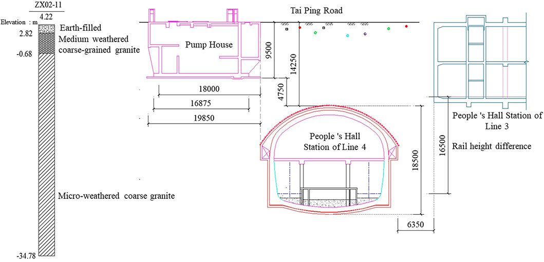
The Line 4 People’s Hall Station of Qingdao Metro is located in the south district of Qingdao, China. It is an 11 m-long, two-story underground island station with a 21.0 m-wide standard section. The station’s overall length is 256.7 m, with an effective platform length of 118 m. Several structures and pipelines surround the People’s Hall Station. Among them, the pump house and existing Line 3 People’s Hall Station are the closest to the supporting project and have the most stringent vibration velocity control, which is critical for protection during the blasting construction period. Figure 1 depicts the positional relationship between the new and existing projects. The pump house is a two-story underground concrete structure with a structure size of 19.85 × 12.00 × 9.50 m (length × width × height). The sidewalls are 0.50 m thick, and the raft foundation is 0.60 m thick. The existing Line 3 People’s Hall Station is a two-story underground island station, with the main structure in service. The Line 4 People’s Hall Station passes through strata with three different grades of surrounding rock conditions, namely, III, IV, and V. As the explosion shock wave has a higher propagation speed in surrounding rocks, this paper selected the III level surrounding rock section for construction influence analysis.
2.2 Original Blasting Design Scheme
The original blasting design scheme was developed by the design institute based on the Safety Regulations for Blasting (GB6722-2014, 2014), Specifications of Excavation Blasting for Hydropower and Water Resources Projects (DL/T 5135-2013, 2013), and the current common tunnel blasting programs.
To reduce the impact of blasting on the adjacent structures in the grade III section, the proposed cut hole charge is 3 kg, and the single hole charge is 0.5 kg. Attributed to the free surface formation, broken rock can fly out of satellite holes and surrounding apertures, and the number of holes that need to be detonated is large. The maximum charge for single-stage detonation is 3.8 kg.
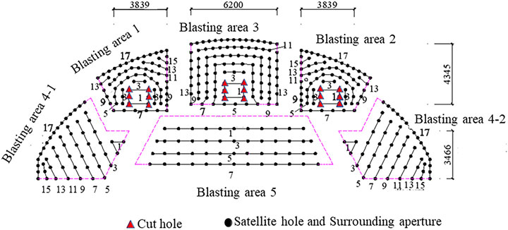
The blasting excavation plan considers the project’s excavation range and geological conditions. Figure 2 illustrates the proposed excavation scheme for the station hall. The station hall layer is depicted in the diagram using the double-sidewall heading method. The different partitions represent the sequence of tunnel section excavation, the solid points represent the satellite hole and surrounding aperture, the triangles represent the cut hole, and the number indicates the detonator segment number.
To ensure the safety of existing structures, control designs and standards for the blasting ground vibration effect caused by the new construction were developed. The peak value of the blasting vibration velocity in existing structures (Zhao et al., 2016; Singh et al., 2020) is used as a control standard. The resultant vibration velocity control values are set at 0.8 cm/s (pump house) and 1.2 cm/s (People’s Hall Station Line 3) for the different types of existing structures.
2.3 Numerical Model
2.3.1 Model Establishment
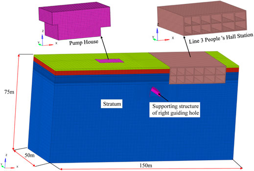
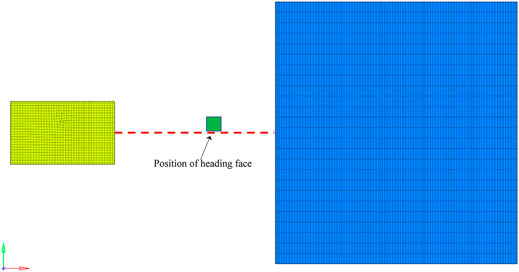
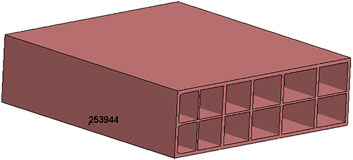
Without regard for the detailed internal structure of existing adjacent structures, we consider only the main structure to establish the numerical model shown in Figure 3. The overall dimensions of the model are 150 × 50 × 75 m (length × width × height). The calculation condition is that the right pilot tunnel is excavated to a depth of 25 m (y = 25 m plane), which places the heading face in the center of Pump House and Line 3 People’s Hall station, as displayed in Figure 4.
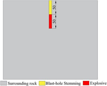
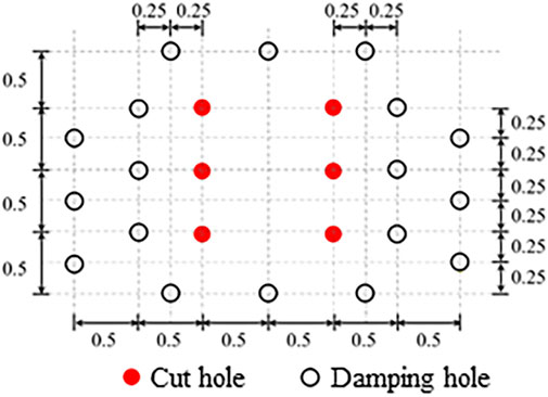
According to the blasting design scheme, the cut hole is continuously charged, with a diameter of 32 mm, a vertical spacing of 50 cm, a horizontal spacing of 1.0 m, a charge length of 50 cm, and a blast-hole stemming length of 50 cm. Figures 5, 6 depict the entire arrangement.
2.3.2 Parameter Selection
2.3.2.1 Selection of Algorithms
The coupling relationship between explosive, water, and blast-hole stemming, as well as large deformation and large displacement, are the main problems that need to be considered in the numerical simulation of tunnel excavation blasting. The ALE algorithm (Soutis et al., 2011) is used to define the water, blast-hole stemming, and explosive models in the numerical calculation process to achieve the dynamic analysis of fluid-solid coupling. The rock mass and structural model are determined by adopting the Lagrange algorithm (Li et al., 2019).
2.3.2.2 Boundary Condition
Given the distance between the stratum boundary and the tunnel area, its displacement can be ignored. Nodal constraints are used in the model to constrain the X-direction displacements on the left and right sides, the Y-direction displacements on the front and rear faces, and the Z-direction displacements on the bottom face. Meanwhile, the Y-direction deformation of adjacent structures is not considered. In its current state, the stratum can be assumed to be a semi-infinite body space, and the blasting vibration wave will be gradually transmitted to the far side along with the stratum. To more accurately simulate the actual condition of blasting vibration, the reflection of stress waves on the stratum boundary should be eliminated in the model. The reflection-free boundary conditions are used in conjunction with ANSYS/LS-DYNA software functions to eliminate the influence of reflected blasting vibration waves, except for the upper surface of the stratigraphic model.
2.3.2.3 Contact Relations
The pump house, the Line 3 People’s Hall Station, and the initial support are all in proximity to the stratum in actual conditions. The model simulates the actual contact relations between these components using the bound surface-to-surface contact method (*CONTACT_TIED_ SURFACE_TO_SURFACE).
2.3.2.4 Material Constitutive and Parameters
The high explosive model (* MAT HIGH EXPLOSIVE BURN) of LS-DYNA is used to model the No. 2 rock emulsion explosive. The state equation of explosive explosion is the Jones-Wilkins-Lee (JWL) equation (Xie et al., 2016), as shown in Eq. 1.
where A, B, R1, R2, and
The constitutive model of water is MAT_NULL. The GRU-NEISEN state equation describes the state of water at high pressure (Man et al., 2018). The pressure
where
The blast-hole stemming material is determined by the (*MAT_SOIL_AND_FOAM) (Lou et al., 2018) state equation, and the solid–gas two-phase medium coupling problem can be effectively described in the simulation process. The parameters are described in Table 3.
For soil and rock mass, the plastic kinematic model (* MAT _ PLASTIC _ KINEMATIC) (Su et al., 2016) containing strain rate is used for simulation. The relevant calculation parameters for rock mass and soil, as well as concrete, are determined in conjunction with the geological survey report and associated specifications, as shown in Table 4.
2.4 Influence of Blasting on Adjacent Structures
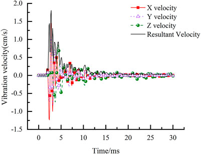
The maximum vibration velocity of the pump house is approximately 0.2 cm/s, and the vibration response of the Line 3 People’s Hall Station is considerably greater than that of the pump house. Figure 8 portrays the vibration velocity curve corresponding to the maximum vibration velocity node (shown in Figure 7: 226,744) near the explosion source side of the Line 3 People’s Hall Station As shown in Figure 8:
1) The vibration response velocity of the Line 3 People’s Hall Station mainly occurred during the early stages of blasting, with the largest vibration response in the horizontal direction. Between 2.5 and 5 ms, the vibration response of the Line 3 People’s Hall Station reaches its maximum value and then gradually decreases until it approaches 0.
2) The peak resultant vibration velocity of the Line 3 People’s Hall Station is 1.80 cm/s, which cannot meet the vibration velocity control requirements of 1.2 cm/s.
3 Optimization Analysis of Water-Sealed Blasting
Water-sealed blasting is a rock-breaking method that employs water as a medium for transmitting explosion energy (Jong-Ho et al., 2007; Ye et al., 2017; Yuan et al., 2019). The properties of water as a medium include low compressibility, high energy transfer efficiency, adsorption of toxic gases generated during blasting, reduction of dust concentration, and improvement of tunnel air quality (Cui et al., 2010; Cui, 2011). Gu et al. (Gu et al., 2015) demonstrated that a water-decoupled charge structure could effectively reduce the instantaneous vibrational energy, resulting in a higher average crushing rate of the rock and less harmful dust. As a consequence, a method of damping via water-sealed blasting construction is proposed.
3.1 Optimization Analysis of Different Charge Structures Blasting
There are three primary types of charging structures frequently used during water-sealed blasting construction: 1) two ends-water-decking charge structure; 2) top-water-decking charge structure; and 3) lower-water-decking charge structure. According to the charge structure distribution shown in Figure 9, the blast-hole stemming length is 50 cm, the charge length is 50 cm, and the water column length is 50 cm.

FIGURE 9. Schematic diagram of different charge structures for hydraulic blasting (unit: cm). (A) Two ends-water-decking charge structure. (B) Top-water-decking charge structure. (C) Lower-water-decking charge structure.
Figure 10 displays the vibration velocity curve extracted from the same node as the previous section for comparative analysis. As illustrated in Figure 10:
1) The resultant vibration velocity caused by the lower-water-decking charge structure is 1.75 cm/s, followed by the two ends-water-decking charge structure at 1.36 cm/s and the top-water-decking charge structure at 1.30 cm/s. The vibration velocities are lowered by 2.8, 24.5, and 27.8%, respectively, when the conditions of the lower-water-decking charge structure, the two ends-water-decking charge structure, or the top-water-decking charge structure are adopted. The existence of water extends the range of detonation energy, disperses the energy, modifies the work effect of energy, and slows the vibration velocity of adjacent structures.
2) The vibration velocity curve of the lower-water-decking charge structure is relatively oscillating, and the shock wave lasts a long time. In comparison to the other two structures, the buffer effect of the water column at the bottom of the model increases the time of shock wave action, the acceleration of vibration, and the velocity of vibration.

FIGURE 10. The resultant vibration velocity response of Line 3 under different charge structure conditions. (A) Two ends-water-decking charge structure. (B) Top-water-decking charge structure. (C) Lower-water-decking charge structure.
In summary, to reduce the vibration response of adjacent structures, the two ends-water-decking charge structure or the top-water-decking charge structure should be selected. Liu and Gao (Liu and Gao, 2020) discovered that the water interval charge at both ends is superior to the other three charge structures in terms of unit explosive consumption, blast-hole utilization rate, and rock fragmentation with the same blasting volume. Additionally, in the two ends-water-decking charge structure, the water medium at the bottom of the hole protects the surrounding rock at the bottom, mitigates the disturbance to the surrounding rock at the bottom of the hole, and ensures construction safety. Therefore, the advantages of the two ends-water-decking charge structure become more apparent during the tunnel construction process.
3.2 Optimization Analysis of Axial Decoupling Charge Coefficient Blasting
According to the analysis in Section 3.1, this analysis adopts two ends-water-decking charge structures and realizes different axial decoupling coefficients by varying the length of the water column at both ends of the borehole. The axial decoupling coefficient model is depicted in Figure 11. The blast-hole stemming is 50 cm long, the explosive is 50 cm long, and the water columns at both ends of the blast-hole are 15, 20, 25, 30, 35, 40, and 50 cm long. The corresponding axial decoupling coefficients are 1.6, 1.8, 2.0, 2.2, 2.4, 2.6, and 3.0. The structure of the axial decoupling coefficient 2.0 is plotted in Figure 9A.
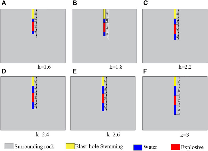
FIGURE 11. Model diagram of different axial decoupling coefficients (unit: cm). (A) k = 1.6, (B) k = 1.8, (C) k = 2.2, (D) k = 2.4, (E) k = 2.6, (F) k = 3.
Figure 12 displays the maximum resultant vibration velocity for varying axial decoupling coefficients. As illustrated in Figure 12, when the axial decoupling coefficient is less than 2.6, the peak vibration velocity decreases as the decoupling coefficient increases. When the decoupling coefficient is higher than 2.6, the peak vibration velocity increases. When the decoupling coefficient is 2.6, the peak vibration velocity is reduced to 1.27 cm/s, and the vibration velocity response of the adjacent structure decreases by 29.5%. This paper considers a charge structure with an axial charge decoupling coefficient of 2.6 for the following optimization analysis of controlled blasting parameters.
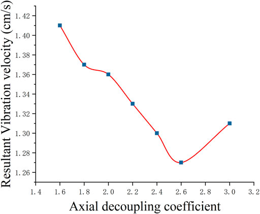
FIGURE 12. The peak resultant vibration velocity response of Line 3 under different axial decoupling coefficients.
4 Optimization Analysis of Controlled Blasting Parameters
Based on the analysis in Section 3, the controlled blasting parameter optimization analysis charge structure model in this section selects the two ends-water-decking charge structure with a decoupling coefficient of 2.6.
4.1 Single Detonation Charge
The vibration velocity response of the Line 3 People’s Hall Station is calculated using single detonation charges of 3, 2.7, and 2.4 kg. The charges for a single cut hole in the model are 0.5, 0.45, and 0.4 kg.
Figure 13 depicts the peak resultant vibration velocity of the Line 3 People’s Hall Station (node 226,744) under the single detonation charge condition. As depicted in Figure 13:
1) The peak resultant vibration velocities are −1.36, −1.10, and −0.90 cm/s of the Line 3 People’s Hall Station on Line 3, respectively, when the single detonation charges are 3, 2.7, and 2.4 kg. According to the 1.2 cm/s vibration velocity control requirements at the Line 3 People’s Hall Station, the single detonation charge of the cut hole should be less than 2.7 kg with a water-decoupled optimization structure charge.
2) When the explosive charge is decreased from 3 to 2.4 kg, the vibration velocities of the water-decoupled optimized charge structure are significantly reduced by 19.1 and 33.8%, respectively. This suggests that controlling the single detonation charge is an effective measure to reduce the vibration velocity response of adjacent structures.
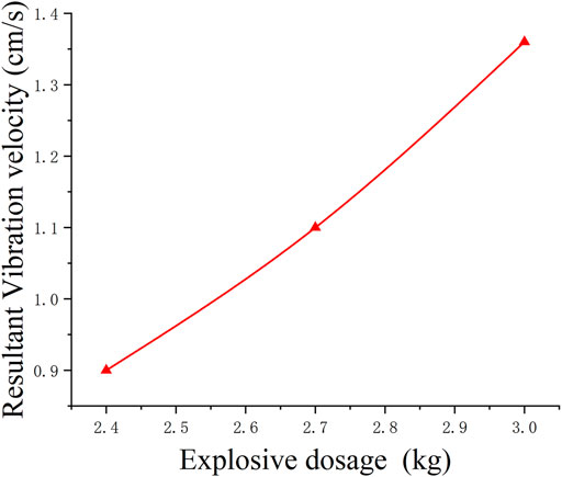
FIGURE 13. The peak resultant vibration velocity response of Line 3 under different explosive dosages.
4.2 Initiation Interval
The small initiation interval will lead to the superposition of explosion shock waves in the transmission process, increasing the peak vibration velocity and causing the vibration velocity of adjacent structures to exceed the allowable value. Consequently, three conditions of initiation intervals of 3, 5, and 10 ms are set in turn to analyze the influence of the initiation interval on the vibration response of existing structures.
The charge amount is 1 kg for a single hole, and the charge amount is 3 kg for a single detonation in this calculation. Detonate the holes further away from the Line 3 People’s Hall Station first and then detonate the holes closer to Line 3. Figure 5 illustrates the hole location; the distance between the two holes is 1.0 m.
The peak resultant vibration velocity of the Line 3 People’s Hall Station (node 226,744) is presented in Figure 14 for varying initiation intervals. As presented in Figure 14:
1) When the initiation interval is 3 ms, the vibration response generated by the second initiation will be superimposed with the first generation. At 5 ms, the vibration response will not be superimposed. From the safety perspective, the initiation interval in the project should be greater than 5 ms to avoid the superimposition of the peak vibration velocity.
2) Under different initiation intervals, the peak vibration velocities generated by the first initiation are 1.41 cm/s greater than the 1.36 cm/s when no interval initiation is used. The peak vibration velocity increases as a result of the initiation being divided into two 3 kg blasts, which causes the initiation to be concentrated so that the peak vibration velocity increases after the initiation.
3) Under different initiation intervals, the peak vibration velocities generated by the first initiation are 1.41 cm/s, and the peak vibration velocities generated by the second initiation are 1.43, 1.42, and 1.44 cm/s, which are greater than those of the first initiation. This is due to the horizontal distance of the second initiation point being 1.0 m closer than that of the first detonation point, so the peak vibration velocity increases, indicating that the detonation distance has a significant influence on the vibration response of adjacent structures, which is consistent with the study by Sharafat et al. (Sharafat et al., 2019).

FIGURE 14. The peak resultant vibration velocity response of Line 3 under different initiation intervals. (A) 3 ms, (B) 5 ms, (C) 10 ms.
4.3 Damping Hole
The damping hole can increase the heterogeneity of rock and soil, alter the wave impedance, and affect the propagation characteristics of blasting seismic waves. Due to the difference in wave impedance characteristics, the blasting vibration wave will be reflected and transmitted when it reaches the damping hole in the tunnel excavation section. The tensile wave will return to the blast zone, a portion of the compression wave will be transmitted, and the transmitted wave intensity will be weakened, reducing the vibration behind the isolation band (Erarslan et al., 2008; Song Z et al., 2019). Therefore, the damping holes are set at the palm surface to analyze its effect on reducing the vibration of existing structures. The damping hole is distributed around the cut hole. The hole depth is 180 cm, and the apertures are 32, 100, and 200 mm. The placement of the holes is depicted in Figure 15. In the model, the charge for a single cut hole was 0.5 kg, and the charge for a single detonation was 3 kg.
The peak resultant vibration velocity of the Line 3 People’s Hall Station (node 226,744) is shown in Figure 16 for varying damping hole diameters. As shown in Figure 16, when the diameters of the damping holes are 32, 100, and 200 mm, the peak vibration velocities of the Line 3 People’s Hall Station are 1.28, 1.10, and 1.02 cm/s, respectively, and the peak resultant vibration velocities are lowered by 5.9, 19.1, and 25%, respectively. The damping holes can indeed reduce the vibration response after blasting. Erarslan and Uysal (Erarslan et al., 2008) also found that when the damping hole is placed between the explosion source and the protection, the damping rate is 14.3–18.5%.
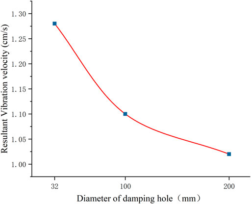
FIGURE 16. The peak resultant vibration velocity response of Line 3 under the different diameters of damping hole.
5 Optimal Damping Effect and Verification of Controlled Blasting for a Water-Sealed Charge Structure
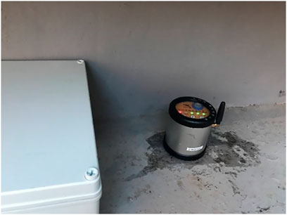
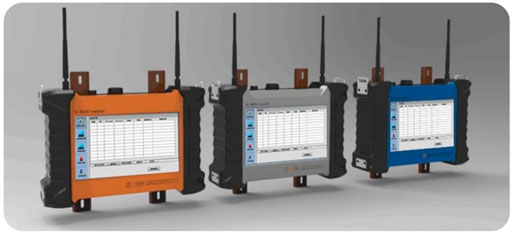
Construction blasting construction in the field was performed with the optimized water-decoupled charge structure. Each cut hole carried a charge of 0.5 kg, while the other hole carried a charge of 0.2 kg. The cut holes in the two pilot tunnels and the middle chamber each had a single detonation charge of 3 kg. The surrounding holes on the upper steps of the two pilot tunnels had a maximum single detonation charge of 3.8 kg. To dampen the cut holes, a few 100 mm damping holes were used. Thunder jumps were employed at 20 ms intervals. The vibration response of the Line 3 People’s Hall Station was monitored in the actual construction process using a TC-6850 vibrometer (Figure 17) and an M600 automatic acquisition terminal (Figure 18). The TC-6850 vibrometer has a range of 25.000 cm/s and a sensing sensitivity (velocity) of 0.01 cm/s. The M600 automated acquisition terminal is capable of having multiple buses to connect a variety of measurement instruments, including inclinometers, axial force gauges, pressure boxes, strain gauges, and vibrometers. Each monitoring project instrument is connected to the M600 automated acquisition terminal for data processing and sending. Figure 19B depicts data from blast vibration monitoring, while Figure 19A depicts data from numerical simulation. The analysis suggests the following:
1) The simulations show that the proposed construction blasting plan can meet the blasting vibration control requirements of the adjacent structures. During the blasting of the cut hole, the vibration velocity in the X direction of the Line 3 People’s Hall Station is the largest, with a peak value of −0.94 cm/s, while the peak vibration velocities in the Y and Z directions are -0.24 cm/s and 0.74 cm/s, respectively, which are lower than the control value of 1.2 cm/s and meet the requirements of construction blasting.
2) The peak vibration velocities monitored at the Line 3 People’s Hall Station were −0.91 cm/s in the X direction, −0.23 cm/s in the Y direction, and 0.72 cm/s in the Z direction. The peak vibration velocities of the three channels were within the tolerance value of 1.2 cm/s, which does not exceed the control tolerance requirement.
(3) The calculated and monitored values indicate that the Line 3 People’s Hall Station has the largest peak vibration velocity in the X direction, with a 3.1% deviation between the calculated and monitored values. The peak deviations of the calculated and monitored values in the y-direction and z-direction are 4.2 and 2.7%, respectively. The calculation model is reliable.
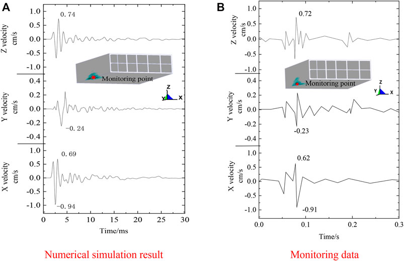
FIGURE 19. The vibration velocity response of the People’s Hall Station on Line 3 induced by blasting construction of Line 4. (A) Numerical simulation resul. (B) Monitoring data.
6 Conclusion
Taking the Line 4 People’s Hall Station of Qingdao Metro as the engineering background, this paper employs a three-dimensional dynamic numerical simulation approach to study the vibration damping effect of water-sealed blasting, single detonation charge, initiation interval, and setting of vibration-damping holes. The site blasting plan is optimized to enable the vibration velocity control to meet the requirement of 1.2 cm/s. Finally, the reliability of the model is verified by the in-site monitored data. The following conclusions can be drawn:
1) Water-sealed construction blasting can significantly decrease the vibration response of adjacent structures. The resultant vibration velocity caused by the lower-water-decking charge structure is 1.75 cm/s, followed by the two ends-water-decking charge structure at 1.36 cm/s and the top-water-decking charge structure at 1.30 cm/s. The vibration velocities are lowered by 2.8, 24.5, and 27.8%, respectively. As the axial decoupling coefficient increases, the peak resultant vibration velocity increases first and then decreases. The peak resultant vibration velocity reaches the minimum value of 1.27 cm/s, which is lowered by 29.5% when the decoupling coefficient is 2.6.
2) When the single detonation charges are 3, 2.7, and 2.4 kg, the peak vibration velocities are −1.36, −1.10, and −0.90 cm/s of the Line 3 People’s Hall Station, respectively, and the vibration velocities are lowered by 19.1 and 33.8%. When the diameters of the damping holes are 32 mm, 100 mm, and 200 mm, the vibration velocities of the Line 3 People’s Hall Station are 1.28, 1.10, and 1.02 cm/s, respectively, and the peak resultant vibration velocities are lowered by 5.9, 19.1, and 25%, respectively.
3) When the detonation charge is reduced to 2.7 kg or 100 mm damping holes are set up, the vibration velocities of Line 3 People’s Hall Station are 1.10 and 1.11 cm/s, respectively. Both velocities are less than the 1.2 cm/s resultant vibration velocity control tolerance requirements.
Data Availability Statement
The original contributions presented in the study are included in the article/Supplementary Material, further inquiries can be directed to the corresponding author.
Author Contributions
CS: Writing review, Editing, and Methodology. YZ: Writing—Original draft, Numerical Simulation, and Analysis. CZ: Numerical Simulation and In-site Monitored. YL: Modification. XS: Modification. XZ: Data curation.
Funding
This work was supported by the National Natural Science Foundation of China (No. 52178402).
Conflict of Interest
The authors declare that the research was conducted in the absence of any commercial or financial relationships that could be construed as a potential conflict of interest.
Publisher’s Note
All claims expressed in this article are solely those of the authors and do not necessarily represent those of their affiliated organizations, or those of the publisher, the editors and the reviewers. Any product that may be evaluated in this article, or claim that may be made by its manufacturer, is not guaranteed or endorsed by the publisher.
Acknowledgments
The authors express their sincere gratitude to all the reviewers for their comments devoted to improving the quality of this paper.
References
Ahmed, L., and Ansell, A. (2012). Structural Dynamic and Stress Wave Models for the Analysis of Shotcrete on Rock Exposed to Blasting. Eng. Structures 35 (Feb), 11–17. doi:10.1016/j.engstruct.2011.10.008
Cheng, R., Zhou, Z., Chen, W., and Hao, H. (2021). Effects of Axial Air Deck on Blast-Induced Ground Vibration. Rock Mech. Rock Eng. 55, 1037–1053. doi:10.1007/s00603-021-02676-9
Cui, Z.-D. (2011). Effect of Water-silt Composite Blasting on the Stability of Rocks Surrounding a Tunnel. Bull. Eng. Geol. Environ. 70 (4), 657–664. doi:10.1007/s10064-010-0346-3
Cui, Z.-D., Yuan, L., and Yan, C.-L. (2010). Water-silt Composite Blasting for Tunneling. Int. J. Rock Mech. Mining Sci. 47 (6), 1034–1037. doi:10.1016/j.ijrmms.2010.06.004
Cunningham, C. V. B., Campos, J., and Robertson, C. (2003). Pre-Set Delay Electronic Detonators: Merits Opposite Programmable Systems. Fragblast 7 (1), 23–33. doi:10.1076/frag.7.1.23.14060
Dindarloo, S. R., Askarnejad, N.-A., and Ataei, M. (2015). Design of Controlled Blasting (Pre-splitting) in Golegohar Iron Ore Mine, Iran. Mining Tech. 124 (1), 64–68. doi:10.1179/1743286314Y.0000000077
DL/T 5135-2013 (2013). Specification of Excavation Blasting for Hydropower and Water Resources Projects. Beijing: China Electric Power Press. (in Chinese).
Erarslan, K., Uysal, Ö., Arpaz, E., and Cebi, M. A. (2008). Barrier Holes and Trench Application to Reduce Blast Induced Vibration in Seyitomer Coal Mine. Environ. Geol. 54 (6), 1325–1331. doi:10.1007/s00254-007-0915-3
Fang, Z., Wang, J., and Mang, J. (2007). Selection of Reasonable Millisecond Interval for Jinduicheng Open-Pit Molybdenum Mine. Prog. Mining Sci. Saf. Technol. Pts A B, 2394–2398.
GB6722-2014 (2014). Safety Regulations for Blasting. Beijing: China Water Power Press. (in Chinese).
Gu, W., Wang, Z., Chen, J., Liu, J., and Lu, M. (2015). Experimental and Theoretical Study on Influence of Different Charging Structures on Blasting Vibration Energy. Shock and Vibration 2015, 1–11. doi:10.1155/2015/248739
He, L., Wang, J., Xiao, J., Tang, L., and Lin, Y. (2013). Pre-Splitting Blasting Vibration Reduction Effect Research on Weak Rock Mass. Disaster Adv. 6, 338–343.
Henningsson, A. (2018). A Model for Vibration Monitoring of Immovable Art in Churches: Reflections on Monitoring as a Tool for Preventive Conservation. Stud. Conservation 63 (Suppl. 1), 113–120. doi:10.1080/00393630.2018.1472913
Inoue, R., Hashimoto, Y., and Yokoyama, Y. (2005). Theoretical Study on Phase Interference Method for Passive Reduction of Multiple Excitation Forces - Reduction Method of Vibration Due to Rhythmic Action of Concert Audience. Environ. Vibrations: Prediction, Monit. Mitigation Eval. (ISEV 2005), 445–452.
Jayasinghe, L. B., Zhao, Z. Y., Goh, A. T. C., Zhou, H. Y., Gui, Y. L., and Tao, M. (2018). A Field Study on Pile Response to Blast-Induced Ground Motion. Soil Dyn. Earthquake Eng. 114, 568–575. doi:10.1016/j.soildyn.2018.08.008
Jiang, N., Gao, T., Zhou, C., and Luo, X. (2018). Effect of Excavation Blasting Vibration on Adjacent Buried Gas Pipeline in a Metro Tunnel. Tunnelling Underground Space Tech. 81, 590–601. doi:10.1016/j.tust.2018.08.022
Jiang, N., and Zhou, C. (2012). Blasting Vibration Safety Criterion for a Tunnel Liner Structure. Tunnelling Underground Space Tech. 32, 52–57. doi:10.1016/j.tust.2012.04.016
Jong-Ho, S., Hoon-G, M., and Sung-Eun, C. (2011). Effect of Blast-Induced Vibration on Existing Tunnels in Soft Rocks. Tunnelling Underground Space Tech. 26 (1), 51–61. doi:10.1016/j.tust.2010.05.004
Jong-Ho, S., Hoon-G, M., and Sung-Eun, C. (2007). Numerical Simulation of Tensile Damage and Blast Crater in Brittle Rock Due to Underground Explosion. Int. J. Rock Mech. Mining Sci. 44 (5), 730–738. doi:10.1016/j.ijrmms.2006.11.004
Jung, Hyuksang., Kyoungsik, Jung., and Hongnyeon, Mun. (2011). A Study on the Vibration Propagation Characteristics of Controlled Blasting Methods and Explosives in Tunnelling. J. Korean Geo-Environmental Soc. 12 (2), 5–14.
Kou, M., Liu, X., Tang, S., and Wang, Y. (2019). Experimental Study of the Prepeak Cyclic Shear Mechanical Behaviors of Artificial Rock Joints with Multiscale Asperities. Soil Dyn. Earthquake Eng. 120 (MAY), 58–74. doi:10.1016/j.soildyn.2019.01.026
Lee, J. S., Ahn, S. K., and Sagong, M. (2016). Attenuation of Blast Vibration in Tunneling Using a Pre-cut Discontinuity. Tunnelling Underground Space Tech. 52, 30–37. doi:10.1016/j.tust.2015.11.010
Lei, Y., Liu, J., Zhang, S., Zhang, W., and Wang, H. (2016). Contrast Test of Different Permeability Improvement Technologies for Gas-Rich Low-Permeability Coal Seams. J. Nat. Gas Sci. Eng. 33, 1282–1290. doi:10.1016/j.jngse.2016.06.066
Li, A., Fang, Q., Zhang, D., Luo, J., and Hong, X. (2018). Blast Vibration of a Large-Span High-Speed Railway Tunnel Based on Microseismic Monitoring. Smart Structures Syst. 21 (5), 561–569. doi:10.12989/sss.2018.21.5.561
Li, H., Zhang, X., Li, D., Wu, L., Gao, W., and Zhou, H. (2019). Numerical Simulation of the Effect of Empty Hole between Adjacent Blast Holes in the Perforation Process of Blasting. Ifs 37 (3), 3137–3148. doi:10.3233/JIFS-179116
Li, X., Long, Y., Ji, C., Zhong, M., and Zhao, H. (2013). Study on the Vibration Effect on Operation Subway Induced by Blasting of an Adjacent Cross Tunnel and the Reducing Vibration Techniques. J. Vibroengineering 15 (3), 1454–1462.
Liu, J.-c., and Gao, W.-x. (2020). Vibration Signal Analysis of Water Seal Blasting Based on Wavelet Threshold Denoising and HHT Transformation. Adv. Civil Eng. 2020 (1), 1–14. doi:10.1155/2020/4381480
Liu, J., Shi, C., Lei, M., Cao, C., and Lin, Y. (2020). Improved Analytical Method for Evaluating the Responses of a Shield Tunnel to Adjacent Excavations and its Application. Tunnelling Underground Space Tech. 98, 103339. doi:10.1016/j.tust.2020.103339
Lou, X., Wang, Z., Chen, B., and Yu, J. (2018). Theoretical Calculation and Experimental Analysis on Initial Shock Pressure of Borehole Wall under Axial Decoupled Charge. Shock and Vibration 2018 (PT6), 1–14. doi:10.1155/2018/7036726
Ma, H., Wang, H., He, C., Zhang, Z., and Ma, X. (2017). Influences of Blasting Sequence on the Vibration Velocity of Surface Particles: A Case Study of Qingdao Metro, China. Geotech Geol. Eng. 35 (1), 485–492. doi:10.1007/s10706-016-0122-7
Man, K., Liu, X., Wang, J., and Wang, X. (2018). Blasting Energy Analysis of the Different Cutting Methods. Shock and Vibration 2018 (PT12), 1–13. doi:10.1155/2018/9419018
Mobaraki, B., and Vaghefi, M. (2015). Numerical Study of the Depth and Cross-Sectional Shape of Tunnel under Surface Explosion. Tunnelling Underground Space Tech. 47 (mar), 114–122. doi:10.1016/j.tust.2015.01.003
Nateghi, R. (2011). Prediction of Ground Vibration Level Induced by Blasting at Different Rock Units. Int. J. Rock Mech. Mining Sci. 48 (6), 899–908. doi:10.1016/j.ijrmms.2011.04.014
Oncu, M. E., Yon, B., Akkoyun, O., and Taskiran, T. (2015). Investigation of Blast-Induced Ground Vibration Effects on Rural Buildings. Struct. Eng. Mech. 54 (3), 545–560. doi:10.12989/sem.2015.54.3.545
Ozacar, V. (2018). New Methodology to Prevent Blasting Damages for Shallow Tunnel. Geomechanics Eng. 15 (6), 1227–1236. doi:10.12989/gae.2018.15.6.1227
Park, D., Jeon, B., and Jeon, S. (2009). A Numerical Study on the Screening of Blast-Induced Waves for Reducing Ground Vibration. Rock Mech. Rock Eng. 42 (3), 449–473. doi:10.1007/s00603-008-0016-y
Saharan, M. R., and Mitri, H. S. (2008). Numerical Procedure for Dynamic Simulation of Discrete Fractures Due to Blasting. Rock Mech. Rock Eng. 41 (3), 641–670. doi:10.1007/s00603-007-0136-9
Sharafat, A., Tanoli, W. A., Raptis, G., and Seo, J. W. (2019). Controlled Blasting in Underground Construction: A Case Study of a Tunnel Plug Demolition in the Neelum Jhelum Hydroelectric Project. Tunnelling underground Space Technol. 93 (Nov), 103098. doi:10.1016/j.tust.2019.103098
Sher, E. N., and Aleksandrova, N. I. (2007). Effect of Borehole Charge Structure on the Parameters of a Failure Zone in Rocks under Blasting. J. Min Sci. 43 (4), 409–417. doi:10.1007/s10913-007-0040-4
Singh, C. P., Agrawal, H., and Mishra, A. K. (2020). A Study on Influence of Blast-Induced Ground Vibration in Dragline Bench Blasting Using Signature Hole Analysis. Arab J. Geosci. 13 (13). doi:10.1007/s12517-020-05562-w
Song, K.-I., Oh, T.-M., and Cho, G.-C. (2014). Precutting of Tunnel Perimeter for Reducing Blasting-Induced Vibration and Damaged Zone - Numerical Analysis. KSCE J. Civ Eng. 18 (4), 1165–1175. doi:10.1007/s12205-014-0393-6
Song, M., Wang, S., Wang, J. B., Sun, Z. Y., Liu, J., and Chang, Y. Z. (2018). Measuring Environment-Biased Technological Progress Considering Energy Saving and Emission Reduction. Process Saf. Environ. Prot. 116 (2), 745–753. doi:10.12989/gae.2018.15.2.74510.1016/j.psep.2017.08.042
Song, S., Li, S., Li, L., Shi, S., Zhou, Z., Liu, Z., et al. (2019). Model Test Study on Vibration Blasting of Large Cross-Section Tunnel with Small Clearance in Horizontal Stratified Surrounding Rock. Tunnelling Underground Space Tech. 92, 103013. doi:10.1016/j.tust.2019.103013
Song, Z., Mao, J., Tian, X., Zhang, Y., and Wang, J. (2019). Optimization Analysis of Controlled Blasting for Passing through Houses at Close Range in Super-large Section Tunnels. Shock and Vibration 2019 (4), 1–16. doi:10.1155/2019/1941436
Soutis, C., Mohamed, G., and Hodzic, A. (2011). Modelling the Structural Response of GLARE Panels to Blast Load. Compos. Structures 94 (1), 267–276. doi:10.1016/j.compstruct.2011.06.014
Su, D., Kang, Y., Li, D., Wang, X., and Yan, F. (2016). Analysis and Numerical Simulation on the Reduction Effect of Stress Waves Caused by Water Jet Slotting Near Blasting Source. Shock and Vibration 2016, 1–18. doi:10.1155/2016/5640947
Tian, X., Song, Z., and Wang, J. (2019). Study on the Propagation Law of Tunnel Blasting Vibration in Stratum and Blasting Vibration Reduction Technology. Soil Dyn. Earthquake Eng. 126, 105813. doi:10.1016/j.soildyn.2019.105813
Uysal, O., Erarslan, K., Cebi, M. A., and Akcakoca, H. (2008). Effect of Barrier Holes on Blast Induced Vibration. Int. J. Rock Mech. Mining Sci. 45 (5), 712–719. doi:10.1016/j.ijrmms.2007.08.008
Wang, J., Ren, Z., Song, Z., Huo, R., and Yang, T. (2019). Study of the Effect of Micro-pore Characteristics and Saturation Degree on the Longitudinal Wave Velocity of sandstone. Arab J. Geosci. 12 (13). doi:10.1007/s12517-019-4566-y
Wang, K., Song, Z., Yang, J., Wang, J., and Zhang, X. (2019). An Escalated Experience of Appreciating Nature. Geomechanics Eng. 17 (4), 393–403. doi:10.12989/gae.2019.17.4.39310.1007/978-981-13-3173-2_17
Wang, T., Lee, C., and Wang, I. (2014). Analysis of Blast-Induced Ground Vibration under Surface Explosion. J. Vibroengineering 16 (5), 2508–2518.
Wang, Y., and Liu, J. (2018). Calculation Model and Decoupling Coefficient Sensitivity Study of Periphery Hole for Eccentric Decoupled Charge in Highway Tunnels. Shock and Vibration 2018, 1–11. doi:10.1155/2018/9734529
Wang, Y. (2017). Study of the Dynamic Fracture Effect Using Slotted Cartridge Decoupling Charge Blasting. Int. J. Rock Mech. Mining Sci. 96, 34–46. doi:10.1016/j.ijrmms.2017.04.015
Xia, X., Li, H. B., Li, J. C., Liu, B., and Yu, C. (2013). A Case Study on Rock Damage Prediction and Control Method for Underground Tunnels Subjected to Adjacent Excavation Blasting. Tunnelling Underground Space Tech. 35 (APR), 1–7. doi:10.1016/j.tust.2012.11.010
Xia, Y., Jiang, N., Zhou, C., and Luo, X. (2019). Safety Assessment of Upper Water Pipeline under the Blasting Vibration Induced by Subway Tunnel Excavation. Eng. Fail. Anal. 104, 626–642. doi:10.1016/j.engfailanal.2019.06.047
Xie, L., Lu, W., Gu, J., and Wang, G. (20182018). Excavation Method of Reducing Blasting Vibration in Complicated Geological Conditions. Shock and Vibration 2018, 1–12. doi:10.1155/2018/2518209
Xie, L. X., Lu, W. B., Zhang, Q. B., Jiang, Q. H., Wang, G. H., and Zhao, J. (2016). Damage Evolution Mechanisms of Rock in Deep Tunnels Induced by Cut Blasting. Tunnelling Underground Space Tech. 58 (sep), 257–270. doi:10.1016/j.tust.2016.06.004
Yang, J. X., and Liu, C. Y. (20172017). Experimental Study and Engineering Practice of Pressured Water Coupling Blasting. Shock and Vibration 2017, 1–12. doi:10.1155/2017/5484598
Ye, Q., Jia, Z., and Zheng, C. (2017). Study on Hydraulic-Controlled Blasting Technology for Pressure Relief and Permeability Improvement in a Deep Hole. J. Pet. Sci. Eng. 159, 433–442. S974225359. doi:10.1016/j.petrol.2017.09.045
Yu, H., Yuan, Y., Yu, G., and Liu, X. (2014). Evaluation of Influence of Vibrations Generated by Blasting Construction on an Existing Tunnel in Soft Soils. Tunnelling Underground Space Tech. 43 (jul), 59–66. doi:10.1016/j.tust.2014.04.005
Yuan, W., Wang, W., Su, X., Wen, L., and Chang, J. (2019). Experimental and Numerical Study on the Effect of Water-Decoupling Charge Structure on the Attenuation of Blasting Stress. Int. J. Rock Mech. Mining Sci. 124, 104133. doi:10.1016/j.ijrmms.2019.104133
Zhang, Y., Luo, Y., Wan, S., Tian, Y., Ding, H., Zhang, X., et al. (2020). Influence of Decoupled Charge Structure and Filler on the Blasting Effect. Shock and Vibration 2020, 1–136. doi:10.1155/2020/8866449
Zhang, Y., Weng, X., Song, Z., and Sun, Y. (2019). Modeling of Loess Soaking Induced Impacts on a Metro Tunnel Using a Water Soaking System in Centrifuge. Geofluids 2019 (4), 1–17. doi:10.1155/2019/5487952
Keywords: metro station, water-sealed blasting, controlled blasting, numerical simulation, decoupled charge structure
Citation: Shi C, Zhao Y, Zhao C, Lou Y, Sun X and Zheng X (2022) Water-Sealed Blasting Control Measures of the Metro Station Undercrossing Existing Structures in Ultra-Close Distances: A Case Study. Front. Earth Sci. 10:848913. doi: 10.3389/feart.2022.848913
Received: 05 January 2022; Accepted: 03 March 2022;
Published: 22 March 2022.
Edited by:
Chong Xu, Ministry of Emergency Management, ChinaReviewed by:
Ming Zhang, China University of Geosciences Wuhan, ChinaChangdong Li, China University of Geosciences Wuhan, China
Copyright © 2022 Shi, Zhao, Zhao, Lou, Sun and Zheng. This is an open-access article distributed under the terms of the Creative Commons Attribution License (CC BY). The use, distribution or reproduction in other forums is permitted, provided the original author(s) and the copyright owner(s) are credited and that the original publication in this journal is cited, in accordance with accepted academic practice. No use, distribution or reproduction is permitted which does not comply with these terms.
*Correspondence: Chenyang Zhao, emhhb2NoZW55YW5nQGNzdS5lZHUuY24=
 Chenghua Shi
 Yiwei Zhao
 Chenyang Zhao*