 Guangfu Chen
 Guodong Zhang1,2
 Fei Guo
 Li Wang
- 1National Field Observation and Research Station of Landslides in Three Gorges Reservoir Area of Yangtze River, Yichang, China
- 2College of Civil Engineering and Architecture, China Three Gorges University, Yichang, China
Anti-slide piles play an important role in landslide control. However, owing to a limitation in the slide–resist design concept, large landslides are difficult to control. Moreover, the displacements of controlled projects are significant. In this paper, we propose an improved anti-slide pile design concept that develops and utilizes the landslide body. On this basis, we also design an arm-stretching-type anti-slide pile structure. We establish formulas for calculating the internal forces of this structure. The results of a case study indicate that the maximum shear force and bending moment of the arm-stretching-type anti-slide pile body were reduced by 43.6% and 25.4%, respectively, compared with those of a conventional single pile. Furthermore, the results of numerical modeling indicate that the arm-stretching-type anti-slide pile could significantly reduce landslide displacement. Thus, the proposed design is expected to solve the problems encountered when using conventional anti-slide piles for landslide control and can thereby become widely applicable in practice.
Introduction
For the control of both artificial (i.e., cut and fill) and natural slopes, anti-slide retaining measures are often adopted. These measures mainly include retaining walls and anti-slide piles (Li et al., 2016; Li et al., 2019; Chen et al., 2020; Liu et al., 2021). A retaining wall is primarily used for the control of small, shallow landslides (Trandafir et al., 2009; Jiang and Towhata, 2013; Muraro et al., 2015), and its construction process has a significant impact on landslide stability. Furthermore, the cost of constructing retaining walls is significantly higher than that of constructing anti-slide piles. Consequently, anti-slide piles have been widely utilized for landslide control (Zhang et al., 2018; Liu et al., 2020; Lei et al., 2021).
Owing to the widespread use of anti-slide piles, various pile structures have been developed, ranging from the single pile to the anchor cable anti-slide pile, the prestressed anti-slide pile, the h-type pile, the door-type pile, and the other combined piles (Bo et al., 2017; Xu et al., 2020). However, the slide–resist concept, which is the design principle for various anti-slide pile structures, has remained unchanged. In other words, the landslide body continues to be regarded only as the source of sliding failure thrust, which is directly resisted by the anti-slide pile (Chow, 1996). Methods for calculating the landslide thrust acting on anti-slide piles embody the slide–resist concept of the anti-slide pile design (Ausilio et al., 2001; He et al., 2015; Wang et al., 2020). Smethurst and Powrie (2007) reported a railway embankment control project that was intended to achieve a high design safety factor; the load transferred to the 0.6-m-diameter anti-slide pile was calculated to be 60 kN using the limit equilibrium method.
According to the slide–resist design concept, the cross-section of an anti-slide pile must be designed to be particularly large; however, because of this, it becomes difficult to control large-scale landslides (Xie et al., 2021). Moreover, defects in the cantilever structure of anti-slide piles can result in substantial deformation under a large thrust (Wang et al., 2020b). Consequently, the use of anti-slide piles is challenging in projects with stringent displacement control requirements. These two factors limit the application of anti-slide piles in landslide control and thus restrict their further development. Notably, both these factors stem from the limitation of the existing design concept of anti-slide piles.
To address this issue, an improved design concept for anti-slide piles is proposed herein, which involves developing and utilizing the landslide body in the anti-slide pile design. Based on this improved design concept, the force of the landslide body can be leveraged in a positive manner. Accordingly, the contradictory relationship between the anti-slide pile and the landslide body can be changed, while shifting away from the view that the landslide body is only a hazard. Based on the proposed concept, a new type of anti-slide pile with stretching arms—the arm-stretching-type anti-slide pile—is designed. At the same time, calculation formulas for determining the internal forces of the pile are established. Furthermore, in addition to numerical simulations, the proposed design is employed for a case study. The results indicate that the novel pile can fulfill the proposed design concept of developing and utilizing the landslide body advantageously. The application of this novel anti-slide pile is expected to address the problems that are encountered when using conventional anti-slide piles.
Methodology
Pile Design Concept
The design concept of an anti-slide pile determines its structure, and this structure, in turn, determines the effectiveness of the pile in landslide control. The various anti-slide piles developed to date are based on a single design concept, i.e., the slide–resist concept. In this concept, the landslide body is regarded as a hazard, and the landslide body and the anti-slide pile are perceived to be two opposing forces; this limits further development and application of anti-slide piles.
To improve the design concept of anti-slide piles, it is thus necessary to determine whether the landslide body can be employed in the control mechanism. If that is, the case, the manner in which it can be applied must be elucidated.
Herein, we propose developing and utilizing the landslide body with the aid of stretching arms. When a stretching arm is situated at the back of the pile, it is called the back branch. When the back branch stretches horizontally, it divides the landslide body and unload. The landslide body is carried by this branch, such that the soil pressure underneath is reduced, and the overturning moment decreases accordingly. Simultaneously, the landslide body on the branch generates a reverse moment that counteracts the moment generated by the landslide body. This helps distribute the internal force in the pile. When a stretching arm is situated at the front of the pile, it is called the front branch. When the front branch stretches horizontally, it provides a supporting force. In this case, the branch utilizes the reaction force of the soil beneath it. Thus, the disadvantage of the insufficient bending resistance of a cantilever pile is alleviated. The structure of the proposed arm-stretching-type anti-slide pile is illustrated in Figure 1.
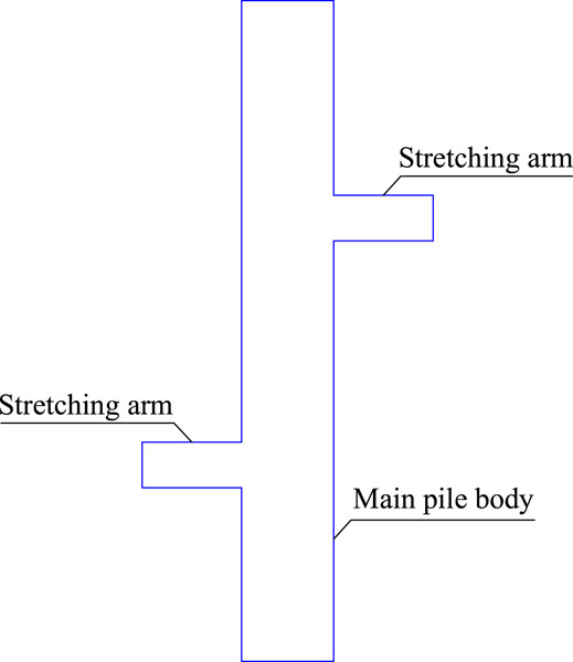
FIGURE 1. Arm-stretching-type anti-slide pile.
Pile Calculation
Based on the elastic foundation theory (Wang et al., 2021), we calculated the internal forces of the arm-stretching-type anti-slide pile. The shear force and bending moment were determined using the cantilever pile method (Conte et al., 2017). Herein, we consider a single stratum as an example.
Load-Bearing Segment
Considering a resistance support in front of the pile, as shown in Figure 2, the following expressions are obtained:
where
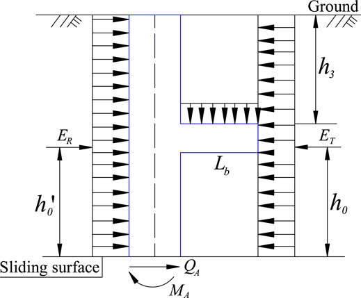
FIGURE 2. Simple representation of load-bearing segment calculation.
Anchorage Segment
The internal forces in the anchorage segment vary according to the conditions of the stratum below the sliding surface. In this study, the internal force of the rigid pile was calculated with the considerations that the pile body is buried in a uniform stratum with the same foundation coefficient of K, and that the bottom of the pile is free.
When
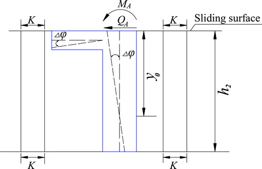
FIGURE 3. Simple diagram representing the anchorage segment calculation.
When
As the value of
The lateral force is
The shear force is
This can further be expressed as
In addition, the bending moment is
Thus,
When
Similarly, we have
The shear force is
Furthermore,
The bending moment is
Thus,
According to the static balance equation,
We thus obtain
Upon solving the two equations, we obtain
Comparative Research Through a Case Study
One of the objectives of designing and applying the proposed arm-stretching-type anti-slide pile is to reduce the need for a large cross-section of piles, which will help control large-scale landslides. For a given application, if the internal force of the arm-stretching-type anti-slide pile is less than that of the conventional single pile, the cross-section of the pile can be reduced to realize control over large landslides. This section presents a comparative study of project control.
Project Data
Above its sliding surface, a landslide is primarily composed of sandy conglomerate and mudstone (The Second Survey and Design Institute of the Ministry of Railways, 1983). These materials are highly weathered and almost soil-like, and they are also uniformly deformed throughout their height. In this case,
The thicknesses of the landslide body before and after the anti-slide pile are similar. The landslide thrust,
Pile Design
The length of the pile is 15 m, the load-bearing segment
Pile spacing
Pile cross-sectional area:
Pile section inertia moment:
Pile section modulus:
Pile elastic modulus (concrete 200):
Pile flexural rigidity:
Pile calculation width:
Pile deformation coefficient:
Pile calculation depth:
External Force Calculation
The landslide thrust acting on each pile is
According to the rectangular distribution, we obtain
The passive earth pressure in front of the pile can be expressed as
and
Therefore, the residual sliding resistance is considered the stratum resistance acting at the front of the pile.
The residual anti-sliding resistance of each pile is expressed as follows:
According to the rectangular distribution, we obtain
Conventional Single Pile
The calculation model is presented in Figure 4.
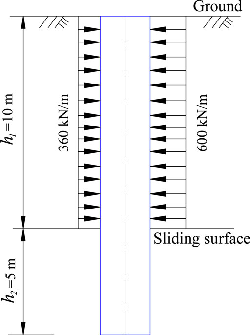
FIGURE 4. Force diagram of the conventional single pile.
Load-Bearing Segment
The shear force is expressed as
The bending moment is
The calculation results for each section are presented in Table 1.
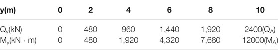
TABLE 1. Internal force of load-bearing segment.
Anchorage Segment
The distance between the sliding surface and the rotation center of the pile—denoted as
The maximum side stress,
The shear force and bending moment of the pile body are calculated using the following formula:
The calculated internal force and side stress of the anchorage segment are listed in Table 2.

TABLE 2. Internal force and side stress of anchorage segment.
Arm-Stretching-Type Anti-Slide Pile
The calculation model is illustrated in Figure 5.
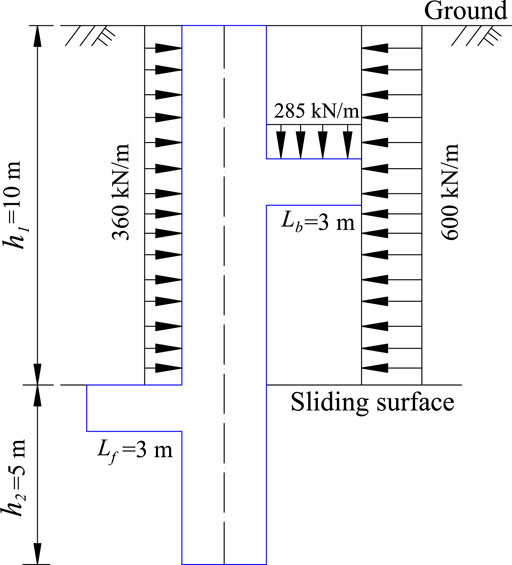
FIGURE 5. Force diagram of the arm-stretching-type anti-slide pile.
Load-Bearing Segment
The shear force is
When
Moreover, when
The calculation results for each section are presented in Table 3.
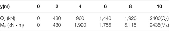
TABLE 3. Internal force of load-bearing segment.
Anchorage Segment
The distance between the sliding surface and the rotation center of the pile according to Eq. 22 is
The rotation angle of the pile according to Eq. 21 is
The side stress of the pile according to Eq. 5 or Eq. 12 is
The maximum side stress occurs at
The pile body shear force according to Eq. 7 or Eq. 14 is
The pile body bending moment according to Eq. 9 or Eq. 16 is
The calculated internal force and side stress of the anchorage segment are listed in Table 4.
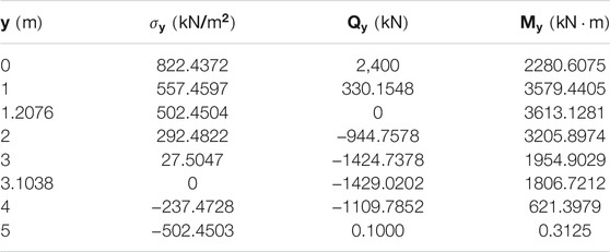
TABLE 4. Internal force and side stress of anchorage segment.
By comparing the calculated internal forces of the conventional single pile and the proposed arm-stretching-type anti-slide pile, it can be concluded that the stretching arms improve the internal force distribution in the pile body and reduce the shear force and bending moment. In the anchorage segment of the pile, the maximum shear force decreases from 4256.2 kN to 2,400 kN, while the maximum bending moment decreases from 12643.1 kN m to 3613.1281 kN m. Thus, the effect of the stretching arms is significant.
Comparative Research Through Numerical Simulations
Another objective of designing and applying the proposed arm-stretching-type anti-slide pile is to alleviate the impact of defects in the cantilever structure of anti-slide piles. Such defects can result in large displacements under the landslide thrust action. In this regard, a comparative simulation study in terms of project control was conducted.
Model Parameters
To verify the engineering applicability of the proposed arm-stretching-type anti-slide pile, the conventional single pile and the proposed pile type were applied in the same project to perform numerical analyses (Shooshpasha and Amirdehi, 2015; Han et al., 2019). A typical three-dimensional landslide anti-slide pile control model was established using ABAQUS (Muraro et al., 2014; Tang et al., 2018; Li and Du, 2021). The mechanical parameters of the landslide and the anti-slide pile are listed in Table 5.
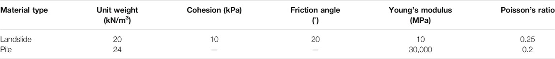
TABLE 5. Model parameters of the anti-slide pile and the landslide used in the simulation.
Figure 6A presents the geometrical parameters of the landslide and the pile. The main pile body has a length of 22 m, width of 1.5 m, and height of 2 m. The stretching arm has a length of 3 m, width of 1.5 m, and height of 1 m. In the numerical simulation, the shaded half-pile model shown in Figure 6B was analyzed on the basis of symmetry (Cai and Ugai, 2000; Li et al., 2015; Yamin et al., 2020; Chen et al., 2021).
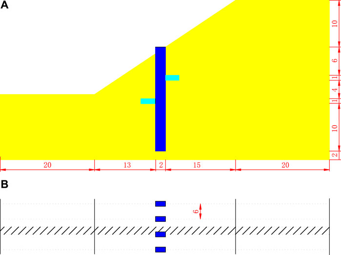
FIGURE 6. Model parameters: (A) longitudinal section and (B) horizontal section.
The Mohr–Coulomb criterion was applied to the landslide during the analysis, and the pile is an isotropic elastic material. The C3D8 unit was used for modeling both the landslide and the pile. The surface-to-surface contact type was adopted to simulate the pile-soil interaction. The pile around and the pile bottom were defined as two surface sets, accordingly, surrounding the soil surfaces were defined. For the normal interaction property, hard contact was used, while the tangential interaction property is defined by the friction coefficient (Liang et al., 2010). Normal constraints were applied to the front, rear, left side, and right side of the model, while the bottom was constrained as fixed.
Result Analysis
The landslide safety factor is 0.922, when the calculation is terminated based on the strength reduction method. Figure 7 shows a cloud map of the plastic strain.
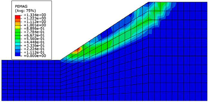
FIGURE 7. Landslide plastic strain cloud map.
The safety factor of the controlled project increased to 1.159 and 1.638 following the conventional single pile treatment and the arm-stretching-type anti-slide pile treatment, respectively. Figure 8 shows the relationship between the safety factor and the horizontal displacement at the slope toe node; this relationship was determined by adopting the two types of piles individually to control the landslide. As shown in Figure 8, regardless of whether the non-convergence of the calculation or the displacement inflection point was employed as the safety factor evaluation criterion, the controlled project safety factor of the arm-stretching-type anti-slide pile is larger than that of the conventional single pile. Furthermore, under the same safety factor, the landslide displacement when using the arm-stretching-type anti-slide pile is significantly smaller than that when using the conventional single pile. Therefore, the new arm-stretching-type anti-slide pile is highly suitable for railway embankments and other projects with stringent requirements in terms of displacement control.
FIGURE 8. Relationship between safety factor and horizontal displacement at the slope toe node.
Figure 9 shows the incremental displacement of the landslide when the calculation is terminated. The figure indicates a difference between the sliding surfaces when using the respective conventional single pile and the arm-stretching-type anti-slide pile. This suggests that the stretching arms can alter the distribution of the landslide forces, and the landslide body can thereby be developed and utilized.
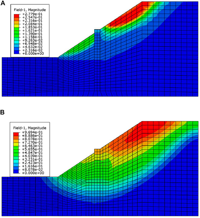
FIGURE 9. Landslide body incremental displacement cloud map: (A) conventional single pile and (B) arm-stretching-type anti-slide pile.
Figure 10 shows the shear force and the bending moment of the pile when the strength reduction analysis step is terminated. It is evident that the shear force and bending moment of the arm-stretching-type anti-slide pile decrease significantly along the main pile body. The great improvement could be result of the synergistic action of the front branch’s supporting effect and the back branch’s unloading effect. The shear force decreases from a maximum of 1,250 kN–482 kN, whereas the bending moment decreases from a maximum of 8,570 kN m–1,290 kN m.
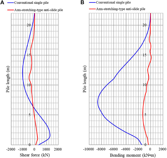
FIGURE 10. Internal forces of conventional single pile and arm-stretching-type anti-slide pile: (A) shear force and (B) bending moment.
Summary and Conclusion
The present study aimed to address the disadvantages of the existing slide–resist concept for designing anti-slide piles: 1) under the existing concept, it is difficult to control large landslides, and 2) this concept is not suited to projects with strict displacement control requirements. To resolve these issues, an improvement to the present single design concept of anti-slide piles was proposed. The new concept addresses the limitation of the slide–resist concept, which deems the landslide body as only a hazard and considers the pile and landslide body to be opposing entities. The proposed concept, in contrast, serves to develop and utilize the landslide body. In accordance with this design concept, the following steps were performed:
(1) An arm-stretching-type anti-slide pile that can realize the proposed design concept of an anti-slide pile was designed, and formulas for calculating the internal forces of the pile body were established.
(2) The internal forces in the conventional single pile and the arm-stretching-type anti-slide pile were investigated and compared through a case study. The results indicated that compared with the maximum shear force of the conventional single pile, that of the arm-stretching-type anti-slide pile decreased by 43.6%, while the maximum bending moment decreased by 25.4%. The cross-section of the arm-stretching-type anti-slide pile can be reduced to less than that of the conventional single pile, which can enable control of large landslides.
(3) Numerical simulations revealed that compared with the internal force of the conventional single pile, that of the arm-stretching-type anti-slide pile is lower and more uniformly distributed. Furthermore, the safety factor of the control project is increased, and the displacement decreases significantly under the same safety factor. The arm-stretching-type anti-slide pile can be adopted for projects with stringent displacement control requirements.
On the basis of these findings, the arm-stretching-type anti-slide pile shows significant potential for practical applications. Considering construction processes, this new type of pile is expected to be particularly suitable for treating filled slopes.
Data Availability Statement
The raw data supporting the conclusion of this article will be made available by the authors, without undue reservation.
Author Contributions
Conceptualization, GC; Supervision, GZ; Software, GC, FG, LW, QZ; Writing—original draft, GC, FG; Writing—review and editing, FG, XH. All authors reviewed the manuscript.
Funding
This work is supported by the Natural Science Research Project of Yichang City (No. A21-3-006), the Open Fund of the Key Laboratory of Geological Hazards on Three Gorges Reservoir Area, Ministry of Education (No. 2017KDZ05), the National Natural Science Foundation of China (No. 42007237, 42107489) and the National Natural Science Foundation Key Projects of China (No. U21A2031).
Conflict of Interest
The authors declare that the research was conducted in the absence of any commercial or financial relationships that could be construed as a potential conflict of interest.
Publisher’s Note
All claims expressed in this article are solely those of the authors and do not necessarily represent those of their affiliated organizations, or those of the publisher, the editors and the reviewers. Any product that may be evaluated in this article, or claim that may be made by its manufacturer, is not guaranteed or endorsed by the publisher.
References
Ausilio, E., Conte, E., and Dente, G. (2001). Stability Analysis of Slopes Reinforced with Piles. Comput. Geotechnics. 28, 591–611. doi:10.1016/S0266-352X(01)00013-1
Bo, Z., Yun-Sheng, W., YuShen, W. T., Tong, S., and Yong-Chao, Z. (2017). Retaining Mechanism and Structural Characteristics of H Type Anti-slide Pile (hTP Pile) and Experience with its Engineering Application. Eng. Geology. 222, 29–37. doi:10.1016/j.enggeo.2017.03.018
Cai, F., and Ugai, K. (2000). Numerical Analysis of the Stability of a Slope Reinforced with Piles. Soils and Foundations. 40, 73–84. doi:10.3208/sandf.40.73
Chen, G., Zou, L., Wang, Q., and Zhang, G. (2020). Pile-spacing Calculation of Anti-slide Pile Based on Soil Arching Effect. Adv. Civil Eng. 2020, 1–6. doi:10.1155/2020/7149379
Chen, H., Li, L., Li, J., and Sun, D. A. (2021). A Rigorous Elastoplastic Load-Transfer Model for Axially Loaded Pile Installed in Saturated Modified Cam-clay Soils. Acta Geotech. doi:10.1007/s11440-021-01248-z
Chow, Y. K. (1996). Analysis of Piles Used for Slope Stabilization. Int. J. Numer. Anal. Methods Geomech. 20, 635–646. doi:10.1002/(sici)1096-9853(199609)20:9<635:aid-nag839>3.0.co;2-x
Conte, E., Troncone, A., and Vena, M. (2017). A Method for the Design of Embedded Cantilever Retaining walls under Static and Seismic Loading. Géotechnique. 67, 1081–1089. doi:10.1680/jgeot.16.P.201
Han, Z., Su, B., Li, Y., Ma, Y., Wang, W., and Chen, G. (2019). Comprehensive Analysis of Landslide Stability and Related Countermeasures: a Case Study of the Lanmuxi Landslide in China. Sci. Rep. 9, 12407. doi:10.1038/s41598-019-48934-3
He, Y., Hazarika, H., Yasufuku, N., Teng, J., Jiang, Z., and Han, Z. (2015). Estimation of Lateral Force Acting on Piles to Stabilize Landslides. Nat. Hazards. 79, 1981–2003. doi:10.1007/s11069-015-1942-0
Jiang, Y.-J., and Towhata, I. (2013). Experimental Study of Dry Granular Flow and Impact Behavior against a Rigid Retaining wall. Rock Mech. Rock Eng. 46, 713–729. doi:10.1007/s00603-012-0293-3
Lei, H., Liu, X., Song, Y., and Xu, Y. (2021). Stability Analysis of Slope Reinforced by Double-Row Stabilizing Piles with Different Locations. Nat. Hazards. 106, 19–42. doi:10.1007/s11069-020-04446-2
Li, C., Liu, Q., Hu, X., Wang, L., and M. a. M., E. E. (2015). Influence of Composite Elastic Modulus and Lateral Load Pattern on Deflection of Anti-slide Pile Head. J. Civ. Eng. Manag. 22, 382–390. doi:10.3846/13923730.2014.897993
Li, C., Wu, J., Tang, H., Wang, J., Chen, F., and Liang, D. (2015). A Novel Optimal Plane Arrangement of Stabilizing Piles Based on Soil Arching Effect and Stability Limit for 3D Colluvial Landslides. Eng. Geology. 195, 236–247. doi:10.1016/j.enggeo.2015.06.018
Li, H., and Du, Q.-w. (2021). Stabilizing a post-landslide Loess Slope with Anti-slide Piles in Yan'an, China. Environ. Earth Sci. 80, 739. doi:10.1007/s12665-021-10051-8
Li, X., Zhao, S., He, S., Yan, Q., and Lei, X. (2019). Seismic Stability Analysis of Gravity Retaining wall Supporting C-φ Soil With Cracks. Soils and Foundations. 59, 1103–1111. doi:10.1016/j.sandf.2019.01.004
Liang, R. Y., Bodour, W. A., Yamin, M., and Joorabchi, A. E. (2010). Analysis Method for Drilled Shaft-Stabilized Slopes Using Arching Concept. Transportation Res. Rec. 2186, 38–46. doi:10.3141/2186-05
Liu, S., Luo, F., and Zhang, G. (2020). Centrifuge Model Tests on Pile-Reinforced Slopes Subjected to Drawdown. J. Rock Mech. Geotechnical Eng. 12, 1290–1300. doi:10.1016/j.jrmge.2020.02.006
Liu, X., Yan, J., Tong, B., and Liu, L. (2021). Evaluation of Micropiles With Different Configuration Settings for Landslide Stabilization Based on Large-Scale Experimental Testing. Front. Earth Sci. 9, 693639. doi:10.3389/feart.2021.693639
Muraro, S., Madaschi, A., and Gajo, A. (2014). On the Reliability of 3D Numerical Analyses on Passive Piles Used for Slope Stabilisation in Frictional Soils. Géotechnique. 64, 486–492. doi:10.1680/geot.13.T.016
Muraro, S., Madaschi, A., and Gajo, A. (2015). Passive Soil Pressure on Sloping Ground and Design of Retaining Structures for Slope Stabilisation. Géotechnique. 65, 507–516. doi:10.1680=geot.14.P.21110.1680/geot.14.p.211
Shooshpasha, I., and Amirdehi, H. A. (2015). Evaluating the Stability of Slope Reinforced with One Row of Free Head Piles. Arab. J. Geosci. 8, 2131–2141. doi:10.1007/s12517-014-1272-7
Smethurst, J. A., and Powrie, W. (2007). Monitoring and Analysis of the Bending Behaviour of Discrete Piles Used to Stabilise a Railway Embankment. Géotechnique. 57, 663–677. doi:10.1680/geot.2007.57.8.663
Tang, L., Cong, S., Xing, W., Ling, X., Geng, L., Nie, Z., et al. (2018). Finite Element Analysis of Lateral Earth Pressure on Sheet Pile walls. Eng. Geology. 244, 146–158. doi:10.1016/j.enggeo.2018.07.030
The second survey and design institute of the ministry of railways (1983). Anti-slide Pile Design and Calculation. 1st ed. Beijing, China: China Railway Publishing House.
Trandafir, A. C., Kamai, T., and Sidle, R. C. (2009). Earthquake-induced Displacements of Gravity Retaining walls and Anchor-Reinforced Slopes. Soil Dyn. Earthquake Eng. 29, 428–437. doi:10.1016/j.soildyn.2008.04.005
Wang, H., Lv, Z., Zhang, J., Yue, J., Qin, H., and Hung, C. (2020a). Internal Force Analysis of Buried-boring Piles in the Yuanzishan Landslide. Appl. Sci. 10, 5416. doi:10.3390/app10165416
Wang, H., Wang, P., Qin, H., Yue, J., and Zhang, J. (2020b). Method to Control the Deformation of Anti-slide Piles in Zhenzilin Landslide. Appl. Sci. 10, 2831. doi:10.3390/app10082831
Wang, J., Liu, J., and Liang, Q. (2021). Internal Force of the Anti-slide Pile in Soil Based on the Deep Beam Model. KSCE J. Civ. Eng. 25, 782–792. doi:10.1007/s12205-021-0161-3
Xie, Q., Cao, Z., Shi, X., Fu, X., Ban, Y., and Wu, Z. (2021). Model Test of Interaction between Load-Caused Landslide and Double-Row Anti-slide Piles by Transparent Soil Material. Arab. J. Sci. Eng. 46, 4841–4856. doi:10.1007/s13369-020-05256-1
Xu, C. J., Ding, H. B., Luo, W. J., Tong, L., Chen, Q. S., and Deng, J. L. (2020). Experimental and Numerical Study on Performance of Long-Short Combined Retaining Piles. Geomech. Eng. 20, 255–265. doi:10.12989/gae.2020.20.3.255
Yamin, M. M., Attom, M. F., and Khan, Z. (2020). Lateral Response of Drilled Shafts in a Moving Cohesive Soil. Int. J. Civ. Eng. 18, 735–742. doi:10.1007/s40999-019-00491-6
Keywords: anti-slide pile, design concept, landslide body development and utilization, arm-stretching-type anti-slide pile, design and calculation
Citation: Chen G, Zhang G, Guo F, Wang L, Zhan Q and Huang X (2022) New Arm-Stretching-Type Anti-Slide Pile Design and Verification. Front. Earth Sci. 10:846616. doi: 10.3389/feart.2022.846616
Received: 31 December 2021; Accepted: 24 January 2022;
Published: 14 February 2022.
Edited by:
Faming Huang, Nanchang University, ChinaReviewed by:
Lin Li, Chang’an University, ChinaLulu Liu, China University of Mining and Technology, China
Baleshwar Singh, Indian Institute of Technology Guwahati, India
Shivanand Mali, Savitribai Phule Pune University, India
Copyright © 2022 Chen, Zhang, Guo, Wang, Zhan and Huang. This is an open-access article distributed under the terms of the Creative Commons Attribution License (CC BY). The use, distribution or reproduction in other forums is permitted, provided the original author(s) and the copyright owner(s) are credited and that the original publication in this journal is cited, in accordance with accepted academic practice. No use, distribution or reproduction is permitted which does not comply with these terms.
*Correspondence: Fei Guo, eWJibnVpLjIwMDhAMTYzLmNvbQ==