- 1State Key Laboratory of Coking Coal Exploitation and Comprehensive Utilization, Pingdingshan, China
- 2College of Safety Science and Engineering, Liaoning Technical University, Huludao, China
In the process of underground energy mining, the stability of roadway support is an important guarantee. In order to study the application of the anchor cable-truss support technology in water-rich soft rock roadways, the mechanical analysis of the anchor cable-truss structure is carried out, and the surrounding rock deformation of different supporting methods is numerically simulated under the consideration of the fluid–solid coupled interaction. We observed that the anchor cable (rod)-double arch truss coupling support can control the deformation of the surrounding rock and the expansion of the plastic zone well. The maximum vault subsidence of the roadway is 0.017 m, the horizontal convergence is 0.054 m, and the deformation of floor heave is 0.02 m, which are 3.8, 16.3, and 4% of the deformation under unsupported conditions, respectively; the roadway deformation is effectively controlled. The research results have certain guiding significance for the support design of the water-rich broken soft rock roadway.
1 Introduction
With the development of underground mine engineering, water-rich and broken soft rock formations are often encountered; the roadway in this kind of stratum will encounter problems such as collapse or large deformation of the vault during construction and use, which will affect the construction progress or normal use, and even cause equipment loss and casualties seriously.
In previous studies, the weakening effect of water on the mechanical parameters of the surrounding rock mass was mainly considered, such as reducing the compressive strength and elastic modulus of the rock mass and reducing the shear strength of the rock mass. Less consideration is given to the effect of water seepage on the surrounding rock mechanics of the roadway (Miao et al., 2004; Yang and Wang, 2006; Ma et al., 2007; Guo et al., 2008; Jing, 2009; Li, 2010; Xie et al., 2010; Zuo et al., 2011; Lu, 2012; Zhang et al., 2014). In this article, the supporting technology of water-rich broken soft rock roadway under seepage action is studied from the perspective of fluid–structure coupling. In the modern roadway support technology, anchor mesh and cable coupling support are generally used to support the soft rock roadway, which can control deformation and restore stability of the roadway. However, due to the poor supporting ability of the anchor mesh cable, the surrounding rock cannot be stable with the passage of time, although the surrounding rock displacement has been greatly controlled for the deep high-stress water-rich broken rock roadway. The arch truss structure is a new mechanical structure; the structure of the truss itself transforms the bending moment into the tension and compression axial force of the rod, and the arc form of the arch transforms the bending moment into the axial force, and the truss arch perfectly combines the two structures organically to achieve the best supporting effect (Yan et al., 2012; Ghabraie et al., 2013; Suchowerska et al., 2014; Yang et al., 2014; Wang et al., 2016; Yan et al., 2017; Wang et al., 2018a; Gao et al., 2018; Li et al., 2019; Su et al., 2019; Yan et al., 2020; Qiu et al., 2022).
2 Research on Deformation Characteristics of the Broken Soft Rock Roadway Considering Fluid–Solid Coupling
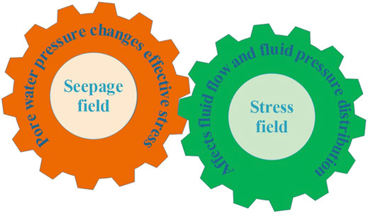
Due to the diagenesis of the rock mass and various physical, chemical, and biological destructive effects, the rock mass in nature has defects such as joints, cracks, and weathering cracks. Groundwater occurs in it, and the migration produces hydrostatic pressing and seepage water pressure; these water pressures affect the rock stress field. At the same time, the effective stress field of the rock also affects the water permeability, which is called the fluid–solid of the seepage field and the stress field. Whose picture is shown in Figure 1 (Meguid et al., 2008; Sadaghiani and Dadizadeh, 2010; Huang et al., 2013; Wang et al., 2018b).
2.1 Influence of Seepage on the Mechanical Action of Rock Mass
In the stress-seepage coupling field, the change in seepage control factors will lead to the change in the coupling field and then affect the stress and displacement distribution of the surrounding rock support. The controlling factors of the seepage field affect rock mass and roadway through the fluid–structure coupling effect. According to the effective stress point of view, σ =σ′+μ, for a certain surface, the total stress perpendicular to the normal direction of the surface is derived from the sum of the effective stress and the pore water pressure. Therefore, when the total stress is constant, the greater the pore water pressure, the less the effective stress acting on the rock mass (Wijk, 1978; Cai et al., 2015; Kai et al., 2015; Chen et al., 2016; Li, 2017; Frith et al., 2018).
Compared with those without fluid–structure coupling, the subsidence value and influence range of the vault and surface after tunnel excavation considering fluid–structure coupling are much larger, and seepage is easy to cause engineering accidents such as large deformation of rock mass and mountain cracking. Peripheral convergence is smaller than that in the case of fluid–structure coupling. The curve of each survey line with the excavation step is very different from that without consideration of fluid–solid regulation.
2.2 Effect of Seepage on Mechanical Parameters of Surrounding Rock Mass
Groundwater seepage will have an impact on the physical, chemical, and mechanical properties of the rock mass. The physical effect is mainly the weakening of the rock mass by water, which promotes the expansion of the original cracks, reduces the strength of the rock mass, and reduces cohesion. Chemical action refers to the dissolution, corrosion, and redox destruction of rock mass by water, which greatly reduces its compressive strength and elastic modulus. Some weak rocks may even collapse and lose strength due to the action of water (Frith and Thomas, 1998; Fuller, 1999; Mark et al., 2001). Formula (1) is the relationship between the uniaxial compressive strength and elastic modulus of the rock and the water content:
where
At the same time, the physical and chemical effects of water also lead to the reduction of cohesion and the internal friction angle in the rock. They are expressed as follows:
where c represents cohesion;
2.3 Numerical Simulation of the Roadway Surrounding Rock Deformation Considering the Fluid–Structure Interaction
After the excavation of a water-rich broken soft rock roadway, the deformation and stress characteristics of rock mass and support structure are very different due to the influence of the seepage field. Through Flac3d numerical simulation, the construction model of the ordinary roadway and the fluid-structure coupling model were established, respectively, for comparative study, and the influence law and the degree of seepage field on the deformation of the surrounding rock support structure of the water-rich broken soft rock roadway were obtained.
2.3.1 Basic Assumptions
1) It is assumed that the surrounding rock of the model is a homogeneous and isotropic seepage media;
2) The pore water is still in the original rock state, and the roadway becomes stable seepage after excavation, and it obeys Darcy’s law of seepage;
3) The model adopts the Mohr–Coulomb constitutive model;
4) Supporting structures such as anchor cables (rods) and trusses are calculated based on linear elastic materials.
2.3.2 Model Scope and Boundary Conditions
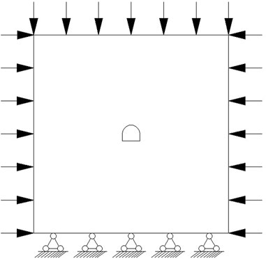
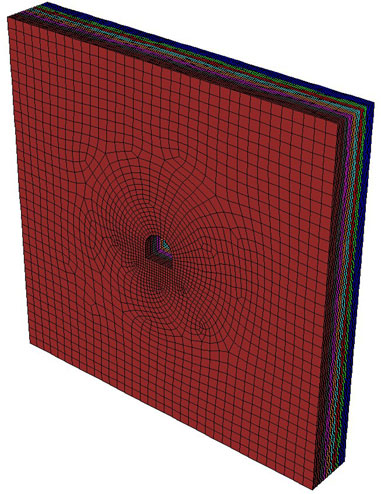
In order to ensure that the roadway is not affected by boundary constraints and to make the calculation simple, we took 35 m on the left and right sides of the roadway axis, 6 m for the front and back; in the vertical direction, we took 35 m for the upper and lower sides. In order to restore the deep in situ stress state, the model adopts uniformly distributed loads on the front and back, with a pressure measurement coefficient of 1.7; the bottom is a fixed boundary, and the upper boundary is set as a uniform load stress boundary, which is determined by the simulated depth and the average weight of the upper overlying rock. The mechanical parameters and seepage parameters of the model are obtained from experiments on uniaxial compression strength and triaxial seepage. Whose picture is shown in Figure 2 and Figure 3.
2.3.3 Test Results and Analysis
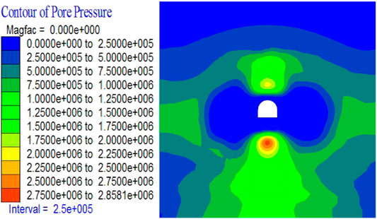
After the excavation of the roadway, the surrounding rock pore water pressure distribution cloud map is shown in Figure 4; the top and bottom of the roadway gather high pore water pressure, and the hydraulic gradient is large, which has a large seepage pressure on the surrounding rock of the roadway, and affects the effective stress field distribution directly, leading to a greater impact on the displacement field of the surrounding rock of the roadway and the deformation of the supporting structure.
Numerical simulation experiments considered three working conditions, namely, ordinary working conditions, considering fluid–structure coupling conditions, and considering both fluid–structure coupling and the weakening effect of water on rock mechanical parameters. Judging from the results of numerical simulations, in Figure 5A and Figure 5D, the fluid–structure coupling interaction is not considered, the maximum amount of roadway vault subsidence is 0.43 m, the maximum bottom heave volume is 0.30 m, and the maximum convergence amount of the side siding on both sides is 0.617 m, and in Figure 5B and Figure 5E, the maximum subsidence of the roadway under consideration of the fluid–structure coupling is 0.36 m, the floor heave is 0.20 m, the horizontal convergence is 0.45 m, and the deformation is less than the working condition without considering the seepage effect. This is mainly because the pore water pressure of the vault and floor reduces the effective stress of the surrounding rock, resulting in a reduction in the amount of deformation; Figure 5C and Figure 5F take into account the influence of groundwater seepage on the stress field and consider the weakening of the mechanical parameters of the rock mass; the maximum amount of dome subsidence reaches 0.44 m, the maximum amount of floor heave is 0.33 m, and the maximum convergence of the two sides is 0.50 m; the vertical deformation exceeds the normal working condition, indicating that considering the influence of fluid–structure coupling, the weakening effect of water seepage on mechanical properties of rock mass exceeds that of mechanics, and the deformation of the surrounding rock is more serious, and the stability is worse.
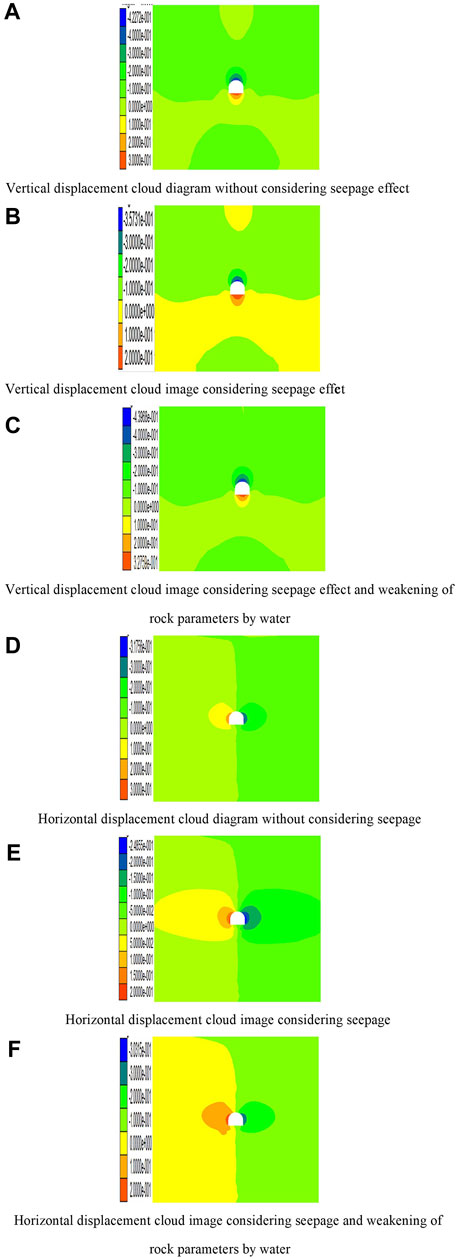
FIGURE 5. Vertical and horizontal displacement nephogram of three different situations. (A) Vertical displacement cloud diagram without considering the seepage effect. (B) Vertical displacement cloud image considering the seepage effect. (C) Vertical displacement cloud image considering the seepage effect and weakening of rock parameters by water. (D) Horizontal displacement cloud diagram without considering seepage. (E) Horizontal displacement cloud image considering seepage. (F). Horizontal displacement cloud image considering seepage and weakening of rock parameters by water.
It can be seen from the three graphs in Figure 6A that the deformation curves at different positions under the three working conditions have consistent characteristics relatively; taking the dome sinking curve as an example, the curve that does not consider the fluid–structure coupling effect is the steepest; it shows that the deformation speed is fast under the action of higher effective stress; under the action of seepage in Figure 6B, the pore water pressure reduces the effective stress, the deformation speed slows down, and the final deformation amount is small. Due to the weakening effect of water on the mechanical properties of the surrounding rock, the compressive strength, elastic modulus, cohesion, and internal friction angle of the rock all have a tendency to decrease, and the amount of deformation expands and exceeds the final deformation amount under ordinary working conditions. The fact that needs to be explained here is that the final level of convergence and stability in Figure 6C is smaller than the normal working condition, which may be caused by the weakening effect being smaller than the mechanical influence of the pore water pressure.
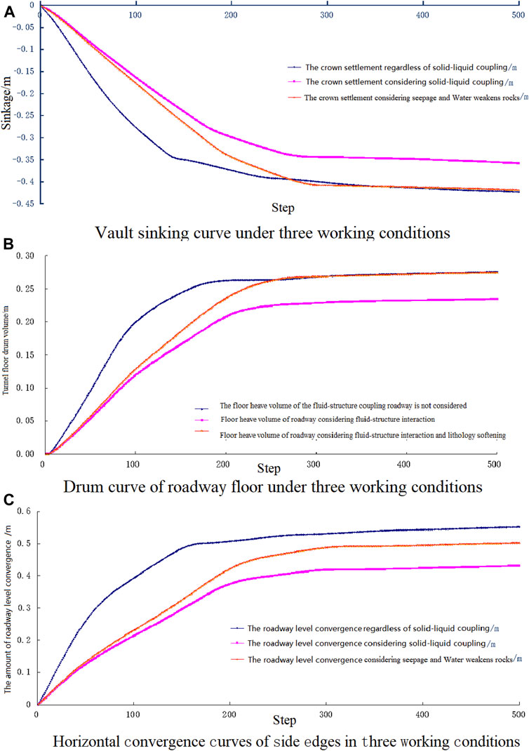
FIGURE 6. Displacement curve in a different position. (A) Vault sinking curve under three working conditions. (B) Drum curve of the roadway floor under three working conditions. (C) Horizontal convergence curves of side edges in three working conditions.
3 Mechanism of the Anchor Cable (Rod)-Truss Coupling Support
From the results of the numerical simulation test in the previous section, it can be seen that the deformation of the roadway is large, which will seriously affect the normal use of the roadway; therefore, it is necessary to control the deformation of the roadway through various supporting technologies. The anchor-cable-truss coupling support researched in this article is a new technology to control the deformation of deep broken soft rock roadways in recent years, which combines active support and passive support well.
3.1Stress Analysis of the Anchor Cable (Rod)-Single Arch Truss Support
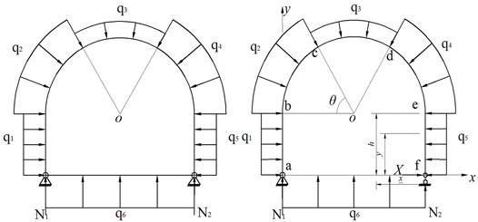
In engineering applications, the truss structure is symmetrical, but due to the anisotropy of the surrounding rock and seepage effects, the load it receives is asymmetrical. Here, for the convenience of analysis, it is simplified to the symmetrical form in the Figure 7. The truss structure is a one-time statically indeterminate structure; the redundant constraint in the fixed hinge support on the bottom side is released and replaced with an unknown force X, the fixed support is converted to a single link support, and the whole truss becomes a statically determinate structure; its mechanical equilibrium equation is described as follows (Kang et al., 2009):
where
In the formula,
3.2 Stress Characteristics of the Anchor Cable (Rod)-Double Arch Truss Support and the Force Characteristics of the Anchor Cable (Rod)-Double Arch Truss Support
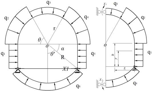
In the deep water-rich broken soft rock roadway, the stress on the surrounding rock of the roadway not only causes serious deformation of the roof and two sides but also has a large amount of bulging of the roadway floor heave, and the instability of the floor, in turn, aggravates the two sides of the arch foot and roof. Therefore, special reinforcement treatment should be carried out on the floor heave of the roadway. For deep mine roadways, the anchor cable (rod)-single arch truss support technology cannot effectively control the floor heave of the roadway; the truss on the floor is also designed as an arch to form a double-arch truss support structure, whose picture is shown in Figure 8.
Substituting
The stress of the support structure should have a certain safety reserve:
where
Similarly, the deformation analysis of the support structure also takes the excess binding force and load as the external load and calculates according to the statically determinate structure:
In this equation, Mp is the bending moment of the simplified truss structure under the combined action of the external load and surplus unknown force X,
3.3 Stress Analysis and the Coupling Principle of the Anchor Cable (Rod)–Truss Structure
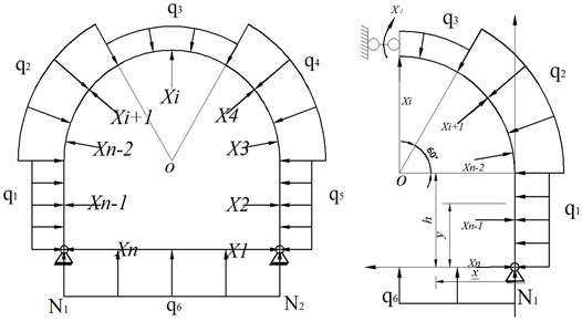
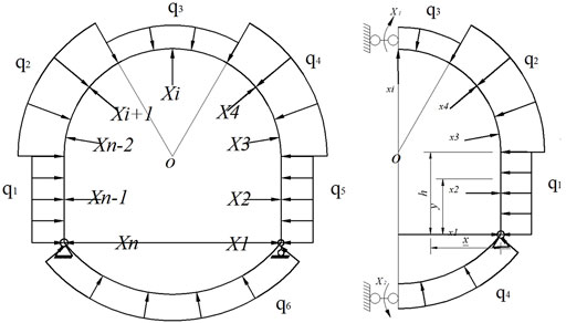
The structural system of the bracket after the supplementary implementation of the anchor cable support is statically indeterminate, and the number of times of statically indeterminate is n. Whose picture is shown in Figure 9 and Figure 10. The force method is used to solve the problem; first, the horizontal link constraint is released in the fixed hinge support F and replaced with the unknown force X; then, the anchor cables are released in the bracket in turn, and they are replaced with unknown forces X2,..., Xn in turn, according to the support. If the structural deformation and the restraint anchor cable deformation are coordinated with each other, the force law equation of the supporting structure can be written as follows (Ranjbarnia et al., 2014):
where
The influence of the shear force and axial force in bearing deformation of support is also ignored:
where Mi, Mj, and Mp are Xi and Xj, which are 1, respectively, and the bending moment of each section of the truss structure is only under the action of the external load, ds is the micro-element of the structure along the axis of the stent, and E and I are the elastic modulus and moment of inertia corresponding to the support structure, respectively.
It is stipulated that the bending moment makes the inner fiber of the arch to be positive; the relevant parameters in the force method equation are calculated based on formula (10), and the unknown force is solved by substituting them into the equation, and then, the internal force, stress, and deformation of the basic structure of the force method are analyzed.
After adopting the anchor cable support technology, the stress concentration of the surrounding rock of roadway is improved to some extent, but due to the characteristics of high expansion, high joint, and high stress of deep broken soft rock, there will still be a stress concentration phenomenon at key positions, resulting in local large deformation. The anchor cable-truss coupling support technology adopts reserved deformation space coupling support, which can release the expansion energy of the surrounding rock effectively. Using double arch truss structure with strong surface protection ability and anchor rope truss arch structure strength of the surrounding deep rock to mobilize the complementary advantages, we improved the integrity of the supporting structure, and through the surrounding rock deformation and reserved space transformation to prevent harmful deformation, with high rigidity of truss with anchor rod support, we improved the support strength and prevented the harmful distortion of joint fissured surrounding rock (Li et al., 2016).
4 Comparative Study on the Numerical Simulation of Different Supporting Effects Considering the Fluid–Structure Interaction
On the basis of the tunnel excavation model established in section 1.3, a comparative study on numerical simulation of different support modes is carried out considering the fluid–structure interaction. The numerical simulation calculation of the anchor cable (rod) support, anchor cable (rod)-single arch truss coupling support, and anchor cable (rod)-double arch truss coupling support are carried out, respectively, and the supporting effect is compared and analyzed (Ghadimi et al., 2016).
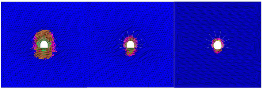
Figure 11 shows the plastic zone of the surrounding rock of the roadway under the three support methods. Under the action of the anchor cable support, the plastic zone of the roadway is elliptical because the tectonic stress is greater than the gravity stress; the long axis of the ellipse is in the vertical direction, and the plastic zone affects the range 2–3 times the diameter of the roadway; however, the influence range of the plastic zone at the bottom of tunnel 3 is relatively large, the coupling support of the anchor cable (rod) and double arch truss solves this problem well, and the range of the plastic zone is only 1.3 times that of the tunnel, achieving a good supporting effect.
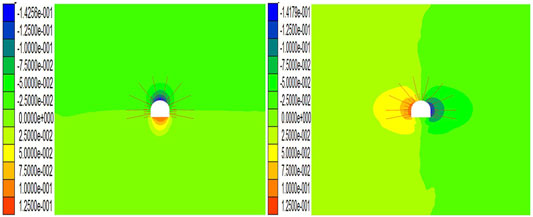
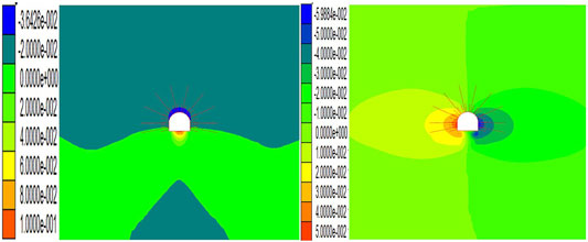
Figures 12, 13 show the displacement cloud diagrams of the anchor cable (rod) support and the anchor cable (rod)-single arch truss support roadway; it can be seen from the figure that the arch of the formerly supported roadway has the largest amount of subsidence being 0.14 m, the bottom drum is 0.12 m, and the horizontal convergence is 0.27 m. Compared with unsupported roadway, the deformation is under certain control, but it cannot meet the support requirements. The latter type of the support reduces the settling of the vault to 0.036 m, which is 25.5% of the former; the horizontal convergence is 0.20 m, which is 74% of the former; the bottom heave volume is 0.10 m, which is 71.4% of the anchor cable (rod) support. It can be seen that the anchor cable (rod)-single arch truss support has played a significant role in controlling the sinking of the vault, but because the bottom of the truss is a straight structure, the bending resistance is poor, and the bottom plate deformation cannot be effectively controlled.
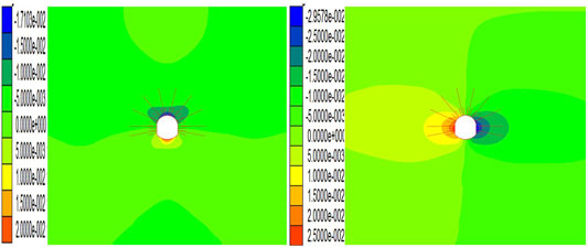
The anchor cable (rod)-single arch truss is designed as a closed overall structure; through the optimized design of the structure, the need for bending and torsion resistance of the truss structure is effectively transformed into tensile, shear, and compression resistance, and the disadvantages of the truss structure turn into an advantage. It can be seen from Figure 14 that with the anchor cable (rod)-double arch truss support, the maximum vault subsidence of the roadway is 0.017 m, the horizontal convergence is 0.054 m, and the bottom heave volume is 0.02 m, which are deformations under the condition of no support 3.8, 16.3, and 4% of the amount; the roadway deformation is obviously controlled.
Figures 15A,C, respectively, show the distribution of the bending moment of the single arch truss and double arch truss before the anchor cable (bar) support is applied, while Figures 15B,D, respectively, show the distribution of the bending moment of the single arch truss and double arch truss after the anchor cable (bar) support is applied. As can be seen from the figure, the potential dangerous surface of the truss, namely, the key parts are located at the bottom angle and side of the truss, especially the bending moment at the bottom angle increases significantly, so the cold pressing one-time molding should be adopted during construction, and the connection must strictly meet the requirements. After the anchor cable (rod) is applied, the bending moment of the truss decreases. The anti-arch structure at the bottom of the roadway not only controls the bottom plate but also reduces the bending moment of the truss; because the anti-arch structure at the bottom of the roadway improves the overall stability of the truss, the bending moment of the haunch, two sides, and basic angle decrease obviously.
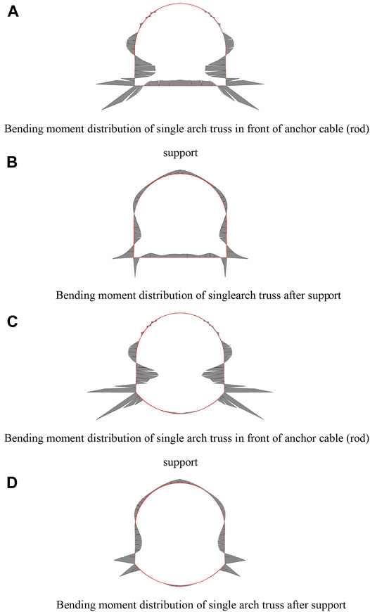
FIGURE 15. Bending moment distribution of the structure. (A) Bending moment distribution of single arch truss in front of the anchor cable (rod) support. (B) Bending moment distribution of the single arch truss after support. (C) Bending moment distribution of the single arch truss in front of the anchor cable (rod) support. (C) Bending moment distribution of the single arch truss after support.
Truss support also has an impact on the anchor cable (bar). Figures 16A,B, respectively, show the axial force of the anchor cable (bar) under the two working conditions of the former without the truss support and the latter with the truss support under the same other conditions. The width of the black line represents the magnitude of the axial force. It can be seen from the figure that after the truss is applied, the axial tension of the anchor cable (rod) is greatly reduced, and the cost of anchor cable rod support can be greatly reduced in engineering practice. At the same time, it can be known that the two support modes interact with each other so that the self-bearing capacity of the roadway surrounding rock can be maximized, and the truss–shallow surrounding rock–anchor cable (rod)–deep surrounding rock are fully coupled to achieve the best support effect.
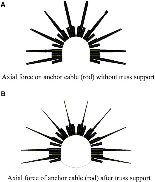
FIGURE 16. Axial force on the front and rear anchor cables supported by truss. (A) Axial force on the anchor cable (rod) without the truss support. (B) Axial force of the anchor cable (rod) after truss support.
5 Conclusion
In this article, the effect of fluid–structure coupling on deformation characteristics of the surrounding rock is studied from the mechanical effect of groundwater seepage on the surrounding rock mass and the weakening effect on physical and mechanical parameters of the rock mass. It is concluded that the pore water pressure reduces effective stress under seepage action, which slows down the deformation speed of the surrounding rock and finally reduces the deformation amount. Due to the weakening effect of water on the mechanical properties of the surrounding rock, the compressive strength, elastic modulus, cohesion, and internal friction angle of the rock all have a decreasing trend, and the amount of deformation expands and exceeds the final deformation under ordinary conditions.
Numerical simulation analysis of the supporting effects of different supporting methods is carried out under the consideration of the fluid–structure coupling effect, and it is observed that the anchor cable (rod)-double-arch truss coupling support can control the surrounding rock deformation and the expansion of the plastic zone well; the maximum vault subsidence of the roadway is 0.017 m, the horizontal convergence is 0.054 m, and the floor heave volume is 0.02 m, which are 3.8, 16.3 and 4% of the deformation under unsupported conditions, respectively. Roadway deformation is obviously controlled. To maximize the self-supporting capacity of the surrounding rock of the roadway, the truss–the shallow surrounding rock–the anchor cable (rod)–the deep surrounding rock are fully coupled to achieve the best support effect.
Data Availability Statement
The raw data supporting the conclusion of this article will be made available by the authors, without undue reservation.
Author Contributions
JZ, YW, and XQ contributed to the conception and design of the research. JZ organized and coordinated the research. YW, XQ, and TZ established the model and carried out numerical simulation. JZ, YW, and XQ compared and analyzed the support effects of different support methods. XQ and TZ wrote the first draft of the manuscript. All authors contributed to manuscript revision, read, and approved the submitted version.
Conflict of Interest
The authors declare that the research was conducted in the absence of any commercial or financial relationships that could be construed as a potential conflict of interest.
Publisher’s Note
All claims expressed in this article are solely those of the authors and do not necessarily represent those of their affiliated organizations, or those of the publisher, the editors, and the reviewers. Any product that may be evaluated in this article, or claim that may be made by its manufacturer, is not guaranteed or endorsed by the publisher.
Acknowledgments
This work was supported by the Open Fund Project of the State Key Laboratory of Coking Coal Exploitation and Comprehensive Utilization (41040220171106-2), which is greatly appreciated.
References
Cai, Y., Jiang, Y., Djamaluddin, I., Iura, T., and Esaki, T. (2015). An Analytical Model Considering Interaction Behavior of Grouted Rock Bolts for Convergence-Confinement Method in Tunneling Design. Int. J. Rock Mech. Min. Sci. 76, 112–126. doi:10.1016/j.ijrmms.2015.03.006
Chen, Y., Meng, Q., Xu, G., Wu, H., and Zhang, G. (2016). Bolt-grouting Combined Support Technology in Deep Soft Rock Roadway. Int. J. Min. Sci. Technol. 26 (5), 777–785. doi:10.1016/j.ijmst.2016.06.001
Fahimifar, A., and Ranjbarnia, M. (2009). Analytical Approach for the Design of Active Grouted Rockbolts in Tunnel Stability Based on Convergence-Confinement Method. Tunn. Undergr. Space Technol. 24 (4), 363–375. doi:10.1016/j.tust.2008.10.005
Frith, R., and Thomas, R. (1998). The Pre-tensioning Pedigree. Australia's Min. Mon. Undergr. Equip. Technol. 6. 68–72
Frith, R., Reed, G., and Mckinnon, M. (2018). Fundamental Principles of an Effective Reinforcing Roof Bolting Strategy in Horizontally Layered Roof Strata and Areas of Potential Improvement. Int. J. Min. Sci. Technol. 28 (1), 67–77. doi:10.1016/j.ijmst.2017.11.011
Fuller, P. (1999). Keynote Lecture: Roof Strata Reinforcement-Achievements and Challenges. Proceeding Rock Support Reinf. Pract. Min., 405
Gao, R., Yu, B., and Meng, X. (2018). Stress Distribution and Surrounding Rock Control of Mining Near to the Overlying Coal Pillar in the Working Face. Int. J. Min. Sci. Technol. 29, 881–887. doi:10.1016/j.ijmst.2018.07.003
Ghabraie, B., Ren, G., Ghabraie, K., and Xie, Y. M. (2013). A Study on Truss Bolt Mechanism in Controlling Stability of Underground Excavation and Cutter Roof Failure. Geotech. Geol. Eng. 31 (2), 667–682. doi:10.1007/s10706-013-9617-7
Ghadimi, M., Shariar, K., and Jalalifar, H. (2016). A New Analytical Solution for Calculation the Displacement and Shear Stress of Fully Grouted Rock Bolts and Numerical Verifications. Int. J. Min. Sci. Technol. 26 (6), 1073–1079. doi:10.1016/j.ijmst.2016.09.016
Guo, Y., Guo, Y., and Sheng, H. (2008). Stability Behavior and Application of Truss-Arch. Spat. Struct. 14 (4), 41. doi:10.3167/ssi.2008.140102
Huang, F., Zhu, H., Xu, Q., Cai, Y., and Zhuang, X. (2013). The Effect of Weak Interlayer on the Failure Pattern of Rock Mass Around Tunnel - Scaled Model Tests and Numerical Analysis. Tunn. Undergr. Space Technol. 35, 207–218. doi:10.1016/j.tust.2012.06.014
Jing, S. (2009). Study on Control Mechanism of Cooperating Support of Frame and Anchor Cable in Soft Fragmmentized Surrounding Rock Poadway with High Stress. Xuzhou: China University of Mining and Technology.
Kai, Z., Zhang, G., Hou, R., Wu, Y., and Zhou, H. (2015). Stress Evolution in Roadway Rock Bolts During Mining in a Fully Mechanized Longwall Face, and an Evaluation of Rock Bolt Support Design. Rock Mech. Rock Eng. 48 (1), 333–344. doi:10.1007/s00603-014-0546-4
Kang, H., Lin, J., and Wu, Y. (2009). Development of High Pretensioned and Intensive Supporting System and its Application in Coal Mine Roadways. Proc. Int. Conf. Min. Sci. Technol. 1, 479. doi:10.1016/j.proeps.2009.09.076
Li, C. C. (2017). Principles of Rockbolting Design. J. Rock Mech. Geotechnical Eng. 9 (3), 14–32. doi:10.1016/j.jrmge.2017.04.002
Li, X., Aziz, N., Mirzaghorbanali, A., and Nemcik, J. (2016). Behavior of Fiber Glass Bolts, Rock Bolts and Cable Bolts in Shear. Rock Mech. Rock Eng. 49 (7), 2723–2735. doi:10.1007/s00603-015-0907-7
Li, Y., Lei, M., Wang, H., Li, C., Li, W., Tao, Y., et al. (2019). Abutment Pressure Distribution for Longwall Face Mining through Abandoned Roadways. Int. J. Min. Sci. Technol. 29, 59–64. doi:10.1016/j.ijmst.2018.11.018
Lu, P. (2012). The Research on Mechanical Characteristics and Reasonable Grouting Parameters Considering the Coupling of Fluid and Solid in Water-Rich Tunnel with Soft Rock. Hunan: Cebtral South University.
Ma, L., Zhamg, D., and Chen, T. (2007). Study on Packing Body Supporting Resistance of Enter in Packing for In-Situ Gob-Side Entry Retaining in Fully-Mechanized Top-Coal Caving Mining Face. Chin. J. Rock Mech. Eng. 26 (3), 544. doi:10.1016/S1872-2067(07)60020-5
Mark, C., Molinda, G. M., and Dolinar, D. R. (2001). Analysis of Roof Bolt Systems. Morgantown: Coal International.
Meguid, M. A., Saada, O., Nunes, M. A., and Mattar, J. (2008). Physical Modeling of Tunnels in Soft Ground: A Review. Tunn. Undergr. Space Technol. 23 (2), 185–198. doi:10.1016/j.tust.2007.02.003
Qiu, H., Zhang, F., Liu, L., Huan, C., Hou, D., and Kang, W. (2022). Experimental Study on Acoustic Emission Characteristics of Cemented Rock-Tailings Backfill. Constr. Build. Mater. 315 (2022), 125278. doi:10.1016/j.conbuildmat.2021.125278
Ranjbarnia, M., Fahimifar, A., and Oreste, P. (2014). A Simplified Model to Study the Behavior of Pre-tensioned Fully Grouted Bolts Around Tunnels and to Analyze the More Important Influencing Parameters. J. Min. Sci. 50 (3), 533–548. doi:10.1134/s1062739114030156
Sadaghiani, M. H., and Dadizadeh, S. (2010). Study on the Effect of a New Construction Method for a Large Span Metro Underground Station in Tabriz-Iran. Tunn. Undergr. Space Technol. 25 (1), 63–69. doi:10.1016/j.tust.2009.08.004
Su, J. M., Jiang, L. S., Kong, P., Wang, P., and Zhang, P. P. (2019). Numerical Modeling Approach on Mining Induced Strata Structural Behavior by Considering the Fracture-Weakening Effect on Rock Mass. Appl. Sci. 9, 1832. doi:10.3390/app9091832
Suchowerska, A. M., Carter, J. P., and Merifield, R. S. (2014). Horizontal Stress under Supercritical Longwall Panels. Int. J. Rock Mech. Min. Sci. 70, 240. doi:10.1016/j.ijrmms.2014.03.009
Wang, P., Jiang, L., Li, X., Qin, G., and Wang, E. (2018). Physical Simulation of Mining Effect Caused by a Fault Tectonic. Arab. J. Geosci. 11. 741. doi:10.1007/s12517-018-4088-z
Wang, Q., Jiang, B., Li, S. C., Wang, D. C., Wang, F. Q., Li, W. T., et al. (2016). Experimental Studies on the Mechanical Properties and Deformation & Failure Mechanism of U-type Confined Concrete Arch Centering. Tunn. Undergr. Space Technol. 51, 20–29. doi:10.1016/j.tust.2015.10.010
Wang, Q., Jiang, B., Pan, R., Li, S.-C., He, M.-C., Sun, H.-B., et al. (2018). Failure Mechanism of Surrounding Rock with High Stress and Confined Concrete Support System. Int. J. Rock Mech. Min. Sci. 102, 89–100. doi:10.1016/j.ijrmms.2018.01.020
Wijk, G. (1978). A Theoretical Remark on the Stress Field Around Prestressed Rock Bolts. Proc. Int. J. Rock Mech. Min. Sci. Geomechanics Abstr. 15, 289
Xie, W., Jing, S., and Wang, T. (2010). Structural Stability of U-Steel Support and its Control Technology. Chin. J. Rock Mech. Eng. 29 (Suppl. 2), 3743
Yan, H., He, F.-L., Li, L.-Y., Feng, R.-M., and Xing, P.-F. (2017). Control Mechanism of a Cable Truss System for Stability of Roadways within Thick Coal Seams. J. Cent. South Univ. 24 (5), 1098–1110. doi:10.1007/s11771-017-3513-x
Yan, H., Zhang, J., Ruimin, F., Wang, W., Lan, Y., and Xu, Z. (2020). Surrounding Rock Failure Analysis of Retreating Roadways and the Control Technique for Extra-thick Coal Seams under Fully-Mechanized Top Caving and Intensive Mining Conditions: A Case Study. Tunn. Undergr. Space Technol. 97, 1–17. doi:10.1016/j.tust.2019.103241
Yan, H., Xu, T. F., and Li, Y. (2012). Experimental Study on Double Truss Cable Supporting System of Coal Roadways in the Isolated Coal Pillar and Fold Region. Amm 214, 296–300. doi:10.4028/www.scientific.net/amm.214.296
Yang, H., and Wang, M. (2006). Numerical Simulation of Seepage in Deep-Buried Long and Big Tunnels. Chin. J. Rock Mech. Eng. 25 (3), 511
Yang, W., Lin, B.-q., Yan, Q., and Zhai, C. (2014). Stress Redistribution of Longwall Mining Stope and Gas Control of Multi-Layer Coal Seams. Int. J. Rock Mech. Min. Sci. 72, 8–15.
Zhang, H., Zhang, J., and Yao, W. (2014). Theoretical Research and Application on Anchor Cable Space of Synergetic Support for U-Shaped Shed and Anchor Cable. J. Min. Saf. Eng. 31 (4), 593. doi:10.13545/j.issn1673-3363.2014.04.016
Keywords: fluid–structure coupling, anchor-truss support, numerical simulation, water-rich soft rock, surrounding rock deformation
Citation: Zhang J, Wang Y, Qi X and Zhu T (2022) Research on Application of the Bolt-Truss Coupling Support Technology in Roadway With Water-Rich and Soft Rock. Front. Earth Sci. 10:842672. doi: 10.3389/feart.2022.842672
Received: 24 December 2021; Accepted: 30 May 2022;
Published: 14 July 2022.
Edited by:
Junbao Wang, Xi’an University of Architecture and Technology, ChinaReviewed by:
Huafu Qiu, Xi’an University of Science and Technology, ChinaJunping Zhou, Chongqing University, China
Copyright © 2022 Zhang, Wang, Qi and Zhu. This is an open-access article distributed under the terms of the Creative Commons Attribution License (CC BY). The use, distribution or reproduction in other forums is permitted, provided the original author(s) and the copyright owner(s) are credited and that the original publication in this journal is cited, in accordance with accepted academic practice. No use, distribution or reproduction is permitted which does not comply with these terms.
*Correspondence: Xiaohan Qi, cXhoODcxMjI1QDEyNi5jb20=
 Jianguo Zhang
 Yingwei Wang1