 Kun Zhang
 Changyou Liu*
 Hanrui Zhang
 Xin Yue
 Huaidong Liu
- School of Mines, China University of Mining and Technology, Xuzhou, China
Based on the application of the retained gob-side entry in a fully mechanized face E2307 headgate, the stress distribution and deformation characteristics of the roadside backfill body for different types of roof cutting were investigated in this study by employing a combination method of theoretical analysis, numerical simulation, and field measurement. The study uses RocLab software to accurately modify the lithology of the simulation area, discuss the position of roof cutting and the pressure relief parameters of roof cutting, and select the optimal solution of the roof-cutting plan. The results show that the advanced pre-cracking effectively blocks the stress transmission in the high-level roof strata; the roadway is in the stress unloading zone, the stress environment of the surrounding rock in the roadway is significantly optimized, and the deformation of the surrounding rock in the roadway is significantly reduced. In the roof-cutting scheme, the deformation of the surrounding rock in the 90° main roof-cutting scheme is reduced by 78% compared with the uncut roof and by 39% compared with the 90° immediate roof cutting. The research results were successfully applied at the E2307 headgate of the Gaohe coal mine; the maximum roof subsidence and the maximum rib convergence were 121 and 74 mm, respectively. Field monitoring indicates that the deformation of the retained entry was controllable, and the final retaining effects were good.
1 Introduction
The longwall mining method is the most mainstream application of coal mining methods in China. Chain pillars can effectively provide stress buffers for adjacent longwall face, mining replacement, and gas isolation. However, coal pillars also caused problems such as waste of resource and hidden dangers of spontaneous combustion of coal pillars (Hou et al., 2019; He et al., 2017). The gob-side entry retaining solves this problem to a large extent. On the one hand, it reduces the waste of resource; on the other hand, it reduces the amount of roadway excavation and optimizes the ventilation method. But roadside backfilling leads to increased stress on the surrounding rock of the roadway and damage to the roof structure. Excessive confining pressure of the roadway is not conducive to support. The study adopts the roof-cutting pressure relief technology, which changes the stress environment of the roadway by adjusting the occurrence state of the roof. It can cut the roof according to the design position, block the stress transmission of the roof, and place it in the pressure relief zone, eliminating the threat of the high stress environment. So that the roadway is in the stress unloading zone, which is conducive to roadway maintenance, reduces the difficulty of support, and greatly reduces the construction cost and time (Chen et al., 2012; Liu et al., 20192019; Ma et al., 2021).
In the study of the surrounding rock stress of gob-side entry, the most important thing to be studied is the roof pressure above the roadway. Zhang et al. conducted in-depth studies from the composite characteristics of the roof structure, deformation, and migration law of the roadway surrounding the rock, stability of the roadway surrounding the rock, and stability of the load-bearing structure, through theoretical analysis, numerical simulation, and field investigation; it is proposed that the stability of the surrounding rock of a roadway in gob-side entry retaining is improved by roof cutting and pressure relief, and it is concluded that the large amount of elastic energy stored in the hard roof in the gob-side entry retaining is the main reason for roadway instability (Li et al., 2012; Han et al., 2013a; Zhang et al., 2014; Ning et al., 2018). Han et al. proposed that the “three-high strength” bolt and cable support technology should be adopted in the gob-side entry retaining, and the segmented and zoned control of the surrounding rock in space and time should be carried out in combination with the single pillar (Zhang et al., 2012; Han et al., 2013b). Yu et al. established the mechanical model of a cantilever beam of roof cutting and studied the roof deformation law and the key factors; it is concluded that the turning angle of the roof and the width of the narrow coal pillar have an important influence on roof deformation, while the cable cannot prevent roof deformation, and give the reasonable cutting top height, and through the field test, results of theoretical calculation are verified (Han et al., 2017; He et al., 2021). He et al. optimized the principle of the roof cutting short-boom beam mining method (110 method) on the premise, systematically expounded the technical parameters of the top-cutting pressure relief, summarized the rule of mining stress distribution in the process of roof-cutting pressure relief, studied the change of stress distribution in the roof during roof-cutting pressure relief through theoretical analysis, and achieved fine effects in the field (Tai et al., 2020; Yu et al., 2020; Liu et al., 2021).
Different materials of roadside packing lead to different mechanical properties of different types, which lead to great differences in the mechanical response. The roadside packing plays an important role in air leakage and prevention of spontaneous combustion in goaf; generally speaking, roadside packing has five materials: wood, waste rock, concrete block, paste filler, and high-water material. At present, paste fillers and high-water materials are gradually replacing the previous traditional materials because of their advantages such as good ventilation and tightness, convenient transport, and good mechanical properties. In addition, Chinese researchers have conducted some experimental studies on the physical and mechanical properties of glass fiber-reinforced plastics prepared with paste filler materials or high-water materials. All of these suggest that the strength and deformability of the roadside packing depends on the proportion of its constituent materials mixed so that for roadside packing with a specific proportion, relevant laboratory tests are essential to ensure a reasonable and scientific mechanical description of its behavior.
Roof cutting has great significance for improving the coal recovery rate, reducing the amount of roadway driving, alleviating the tight connection between mining and excavation, controlling gas at the corners of the longwall face, and extending the service life of the mine. The technology of roof cutting and remained tunnel greatly improves the stress environment of the surrounding rock of the roadway and eliminates the stress concentration above the coal of the adjacent longwall face.
The supporting strength of the roadside backfilling body changes the distribution of the bending moment above the roadway. The supporting strength of the roadside backfilling body not only can cut down the soft coal and immediate roof but also can control roof convergence. However, for a harder and thicker roof, the required supporting strength of the roadside backfilling body is also greater; sometimes the roadside backfilling body with the uncut roof may develop more fissures, which causes the roadway pressure to appear severe (Ma et al., 2018). Aimed at this phenomenon, the study compared and analyzed the plastic zone and stress changes of the surrounding rock of the roadway in different roof-cutting schemes while considering both the strain softening model of coal and the double-yield model of the gangue in the goaf.
2 Background
2.1 Engineering Background
The Gaohe coal mine is located in Changzhi City, Shanxi Province, China (Figure 1). The coal seam is No.3, which lies at an average depth of 638.3 m, with an average thickness and average dip of 3.5 m and 5, respectively. The roof rock strata are, in ascending order, marlstone (2.4 m), siltstone (4.2 m), medium sandstone (4.7 m), and limestone (6.4 m), while those below are, in descending order, mudstone (2.2 m), medium sandstone (2.9 m), and siltstone (4.2 m).
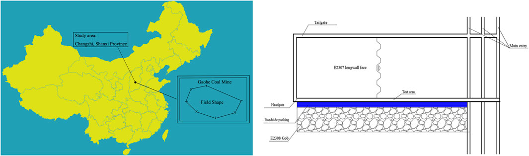
FIGURE 1. Engineering indication.
The bolts with 22 mm in diameter and 2,500 mm in length were used for roof and rib supporting. Roof and ribs bolts were installed with a spacing of 700 mm × 700 mm. In some local areas, anchor cables with 21.8 mm in diameter and 8,800 mm in length were used for reinforced support. The cables were installed with a spacing of 1,400 mm × 1,400 mm. A steel bar ladder beam (14 mm in diameter) and a metal mesh (6 mm in diameter) were used for surrounding rock control (Figure 2).
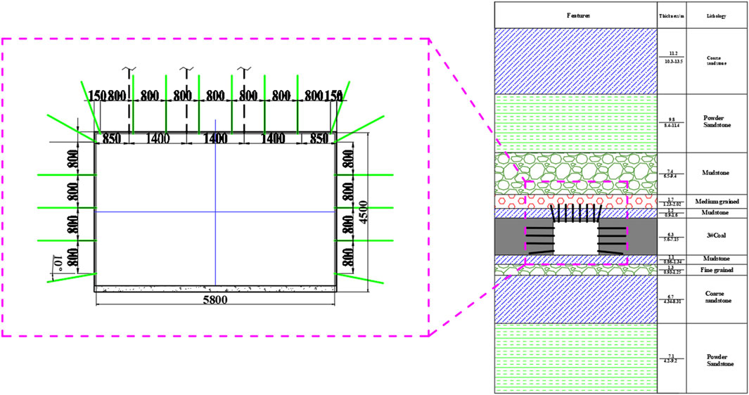
FIGURE 2. Support scheme and generalized stratigraphic column of the shaft station.
The surrounding rock above the E2307 headgate is a hard roof with an average thickness of 25.9 m (Figure 3).
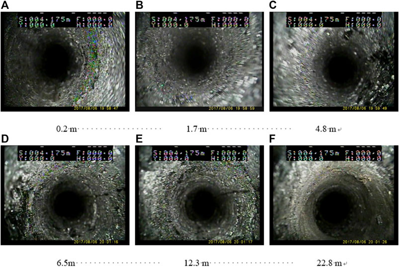
FIGURE 3. E2307 headgate roof occurrence situation. (A) 0.2 m (B) 1.7 m (C) 4.8 m (D) 6.5 m (E) 12.3 m (F) 22.8 m.
Starting from the immediate roof of mudstone (4.9 m), the huge and hard roof with a thickness of 25.9 m has good integrity, and it is difficult for the roof to collapse after mining.
Field observations found that severe entry deformation and supporting system failure occurred about 1 month after the entry excavation (Figure 4). Roof sag was very common in the field; the measured convergence of the roof sag reached up to 1,200 mm, which significantly increased the risk of roof collapse and endangered the safety of workers and equipment. In some areas, there were large-scale roof collapse accidents. Fortunately, there were no casualties. The coal mass of two ribs was fractured into massive loose fragments, resulting in severe extrusion deformation with a maximum convergence of 892 mm in the middle-upper part of the ribs. This large deformation resulted in the conspicuous protuberances on the surface of the sidewalls and the failure of the steel mesh and beams. In addition, floor heave was also quite common, and the displacement induced by the floor heave reached up 256 mm, causing the floor concrete to crack and further compromising the efficiency of underground transportation. As such, the entry exhibited a drastic reduction in the cross section due to severe roof sag, rib convexity, and floor heave; the effective space used for ventilation and coal-mine transportation was less than 7.8 m2, resulting in excessive labor and costs for entry rehabilitation.
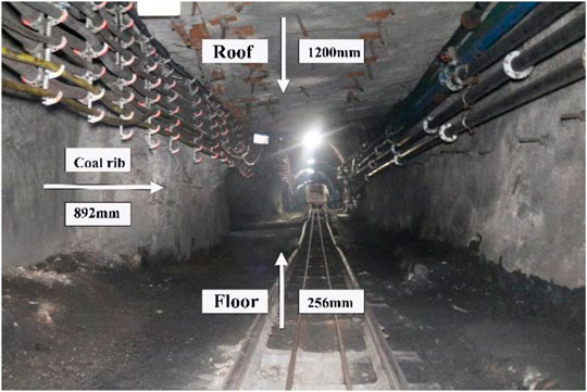
FIGURE 4. Field monitoring and observation of ground stability.
2.2 Rock Mechanics Parameters
In order to have a detailed understanding of the surrounding rock properties of the E2307 headgate, the suitable position of the E2307 headgate was selected to collect coal and rock samples. After being transported to the laboratory for standardized processing (Figure 5), the rock mechanics parameters are measured on the SANS (TAW-2000) machine.
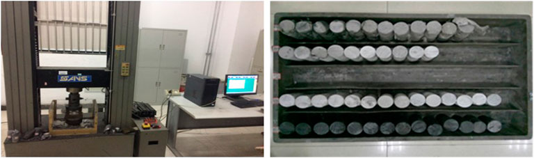
FIGURE 5. Rock mechanics test equipment and samples.
After sampling in the E2307 headgate, standard specimens were made, and the rock parameters were measured, as shown in Table 1.
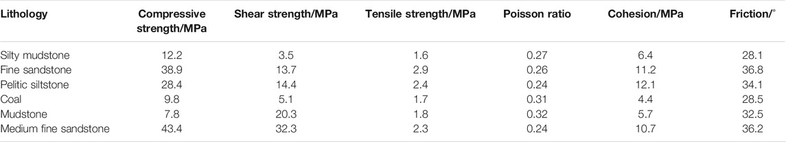
TABLE 1. Measurement results of rock mechanical parameters.
2.3 Summary of the Case Study
Using the rock properties’ experiments and field observation, the ground conditions of the E2307 headgate have been comprehensively investigated. However, excessive deformation and poor stability have become the primary issues, and severe fractures and large deformations can significantly destabilize the surrounding rock, which leads to potential safety issues and economic losses due to E2307 headgate repair and secondary supporting installation. In the following sections, a numerical analysis of the case study is conducted using the three-dimensional finite-difference software FLAC3D. At the same time, calculation and field test are discussed in the following section.
3 Analysis of Pressure Relief Caused by Roof Cutting
Based on the geological and geotechnical conditions of the E2307 headgate, which is decided by field observation, the main roof is broken in the form of “masonry beam,” and the breaking line is located above the E2307 headgate, which causes most of the weight of the rock block B to be applied to the roof of the E2307 headgate. The breaking structure of the overlying strata shows that the surrounding rock of the roadway bears greater vertical stress, which makes roadway supporting more difficult. The present study provides an efficient and simple tool to predict the breaking mode of the main roof and will be helpful to analyze the problems of roof cutting. As the coal seam is mined, the immediate roof will subsequently collapse and sink irregularly, slip, and separate from the main roof above it. After the overburden rock migration is stable, the main roof forms a hinged structure composed of the rock mass A and blocks B and C (Figure 6).

FIGURE 6. Simplified physical model of a lateral cantilever beam.
The roadside backfill body of the E2307 headgate is under the cantilever beam, and the longer thick cantilever causes the roadside backfill body to bear excessive additional load and damage, which leads to the deformation and instability of the surrounding rock structure of the roadway. So the structure B is very important for the stability of the surrounding rock structure of the gob-side entry, and the structure B mainly includes three basic dimensions: the lateral rift size of the main roof (D), the main roof periodic weighting L, and the thickness of the Block B (h). Among them, L is the step length of the main roof cycle compression, which can be obtained by field observation or theoretical calculation; h is the thickness of the basic top rock layer; D is related to the longwall face width S and the main roof periodic weighting L, which can be calculated with the following Eq. 1,
For the force analysis of Block B, the mechanical model of the lateral cantilever beam (Figure 5), which assuming that the uniform roof load is q1 = gH, the integrated coal distributed load σz acts on the line AB, and the supporting resistance p2 in the roadway acts at x0 (s < x0<s+a).
The width of the stress limit equilibrium zone of the coal rib(s) and the distributed load of the integrated coal (σz) are, respectively,
where
P0—supporting strength of the coal rib, MPa;
φ0—the internal friction angle of the interface between the coal seam and the roof and floor rocks, °;
A1—the coefficient of lateral pressure;
g—the bulk density of the overlying strata, N/m3;
k—the stress concentration factor;
H—the mining depth, m;
m—the mining height, m;
c0—the cohesive force of the interface between the coal seam and the roof and floor rocks, MPa; the point A is balanced.
where
For unit-width rectangular cells,
where
Rt—tensile strength of the roof rock, MPa;
H—thickness of the hard immediate roof, m. The ultimate bending moment of the main roof lateral suspension cantilever is Mmax; then, the relationship between the roadside backfilling body supporting strength P1 and the suspension length l is from M1<Mmax.
It can be seen from Eq. 9 that the greater the length of the lateral cantilever beam (l) of the collapsed roof, the greater is the roadside backfilling body supporting strength when the roof is required to be cut. The relationship between the support intensity and length of the cantilever beam can be seen in Figure 7. By controlling the length of the suspended ceiling, the pressure on the filling wall can be reduced, which plays a positive role in supporting the E2307 headgate.
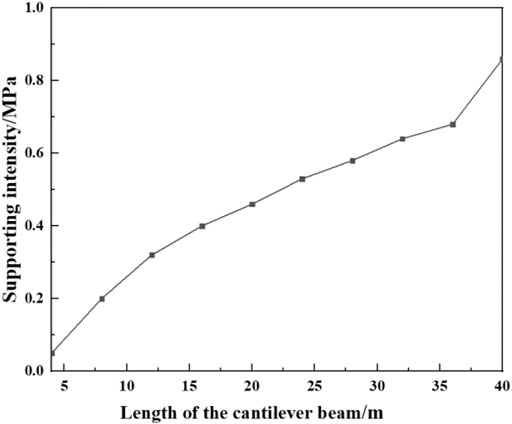
FIGURE 7. Relationship between the support intensity and length of the cantilever beam.
When the main roof breaks at a certain position outside the roadside backfilling body, because the cantilever position of rock block A is longer, it will still cause a series of pressure problems on the roadside backfilling body and the roadway. A certain position above the roadside backfilling body breaks, and even rock block B will not be completely fractured; at this time, the roadside backfilling body bears less pressure from the roof, and the stability of the roadway is the best. The study uses the roof-cutting technology to release pressure (Figure 8).
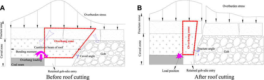
FIGURE 8. Mechanism of roof cutting. (A) Before roof cutting. (B) After roof cutting.
After panel retreat, the caved zone and fracture zone are formed above the gob-side entry during overlying strata breaking and caving, and there will be a cantilever beam above the retained gob-side entry (Figure 7A). Because there is no supporting structure below the cantilever beam, the own weight of the rock and overburden loading of the cantilever area makes it bend, and the loading transforms to the gob gangue and virgin coal rib. Therefore, the existence of a cantilever beam makes it difficult to maintain the stability of the surrounding rock, which has a huge impact on roadway safety. The dam boards were installed at a height of 3.5 m along the gob-side and at a height of 3.4 m in the inner roadway side. A plastic membrane was laid inside of the dam-boards tightly. The width between outside and inside was maintained at 5.0 m. In this study, the roof cutting was performed by deep hole blasting to form a fracturing line above the goaf along the roadway (Figure 7B), and the cantilever beam weight and the overburden load caused it to break along the fracturing line to reduce the overhanging length. It can reduce the influence of its own weight and the load of the overlying rock, improve the stress environment, and ensure the stability of the roadway.
4 Key Parameters of Advanced Cutting and Pressure Relief
According to the above analysis, this study analyzes and compares the two key parameters of the pre-crack cutting roof angle and the pre-crack cutting roof height through accurate numerical simulation calculations and optimizes the plan on this basis to obtain the optimal key parameters of the roof-cutting plan.
4.1 Establishment of the Numerical Model
According to the engineering geological conditions of the E2307 headgate, combined with the measured ground stress and stress data monitoring results, the study uses FLAC3D to establish the model of the E2307 headgate, adjacent goaf, and surrounding rock formations, to compare and analyze the plastic zone distribution, surrounding rock displacement, and stress distribution under different schemes so as to obtain an optimized plan. The average buried depth of the E2307 headgate is 630 m, so the upper load is 15.8 MPa; combined with the ground stress test results, a horizontal stress of 18.9 MPa with a direction angle of 31.55° and an inclination angle of 8.9° is applied (Figure 9).
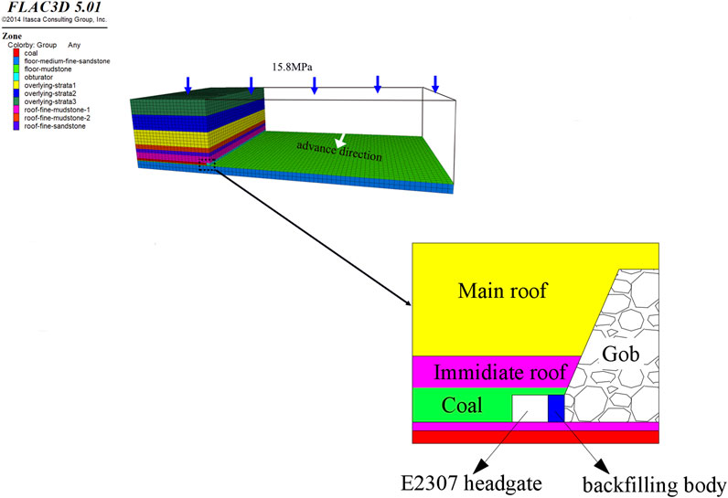
FIGURE 9. Simulation model.
For E2307 headgate roof cutting, two advanced pre-splitting schemes are proposed:
1) Punch the edge of the flexible mold to a vertical depth of 13 m, reaching the main roof;
2) The edge of the flexible mold is punched to a vertical depth of 6 m, reaching the immediate roof. The scheme is shown in Figure 10.
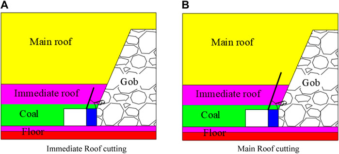
FIGURE 10. Simulation schemes. (A) Immediate roof cutting (B) Main roof cutting.
For the two schemes, pre-splitting schemes with different angles and different depths of pre-splitting holes are proposed, and the summary is shown in Table 2.

TABLE 2. Simulation scheme parameters.
4.2 Parameter Determination
4.2.1 Demonstration of Numerical Accuracy of Top-Cutting Pressure Relief
The numerical simulation is to study the improvement of the stress environment of the surrounding rock of the roadway by different roof-cutting parameters. The double-yield model is used to study the real behavior of the surrounding rock after roof cutting. The volume of the fall and the mined-out area is compressed, and the original surrounding rock support capacity is also increased. According to the previous research study, the input parameters required for the double-yield model are cap pressure and materials’ proper-ties (Bai et al., 2014; Zhang et al., 2015; Bai et al., 2017). The former can be calculated by empirical formulas, and the latter can be obtained by the trial and error method through single-element sub-models:
where σ is the stress of the rock mass, E0 is the strength of the rock mass, and ε is the maximum volumetric strain of the rock mass. Combined previous studies, E0 and ε can be estimated as follows (Wang et al., 2018; Yang et al., 2020):
Here, σc is the strength of the collapsed rock, and b is the expansion coefficient; for the E2307 headgate, σc and b are set to 27 MPa and 1.23, respectively, and εmax and E0 are 0.19 and 65.44 MPa, respectively.
In order to determine the rock parameters of the gob, a unit sub-model of 1 m × 1 m× 1 m was established. The load is simulated by applying different constant strain rates on the top surface of the model (Figure 11).
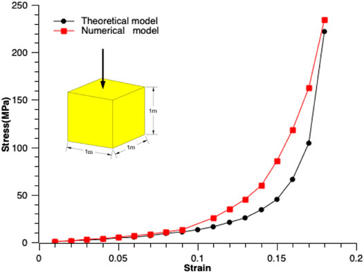
FIGURE 11. Comparison of the stress–strain relationship obtained by the numerical model and Salmon’s model.
The stress–strain curve of the given variable obtained by the formula is fitted by the iterative changes of the volume and modulus, expansion angle, and friction angle of the rock in the mined-out area (Figure 9). The results show that the peak pressure predicted by the model is 223.77 MPa, and the strain is 18.2%. This value is consistent with the calculation result of the formula. The peak pressure predicted by the formula is 220.03 MPa, and the strain is 17.3%. Although the vertical pressure growth rate predicted by the sub-model is faster than that predicted by the formula, in general, the numerical model better predicts the correct rock loading characteristics and shows the calibration characteristics of the materials in the goaf; the double-yield model is relatively accurate.
4.2.2 Parameter Determination
The effect caused by the size gap between the rock sample and the underground rock mass is different; the mechanical parameters of the rock sample measured in the laboratory do not consider the fractures and joints of the rock mass in the formation, and their values cannot truly reflect the mechanical properties of the rock mass (Yang et al., 2019; Zhang et al., 2020). Therefore, the mechanical parameters of rock blocks obtained in the laboratory should be calculated and corrected in the numerical analysis. The study uses RocLab software to modify the rock mechanics parameters.
where
σci is the uniaxial compressive strength, σ1 and σ3 are the maximum and minimum principal stresses, respectively, mb, and s and a are the rock mass constants, which can be obtained by the following formula:
where
mci is the complete rock mass constant, D is the disturbance coefficient, and GSI is the fractured rock mass evaluation parameter.
where
K is the bulk modulus, G is the shear modulus, and v is the Poisson ratio. RocLab software was used to obtain rock mass parameters (Table 3).
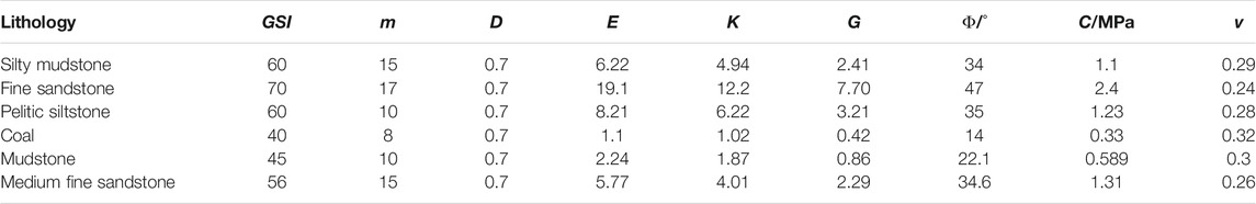
TABLE 3. Rock mass mechanical properties used in numerical simulation.
The failure process of coal can be divided into the elastic phase, plastic phase, and residual phase. It is pointed out that the strain-softening model can more realistically simulate the failure process of coal (Jiang et al., 2017; Zhang et al., 2017). Therefore, this study gives the coal a strain-softening constitutive model, which realizes the mechanical properties of the coal after its destruction by changing the cohesive force and residual angle of the coal (Zhang et al., 2011; Shi et al., 2013; Zhao et al., 2017; Smart and Haley, 2019). The relevant parameters in strain softening are obtained through mechanical tests (Table 4).
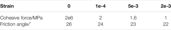
TABLE 4. Coal strain-softening parameter.
4.3 Analysis of the Position Effect of Roof Cutting
4.3.1 Distribution of the Elastic Zone and Plastic Zone
Accordingly, in order to study the position effect of roof cutting for pressure relief, the different cutting angles and lengths were chosen, and the structure variations with different cutting positions (Figure 12) are analyzed.
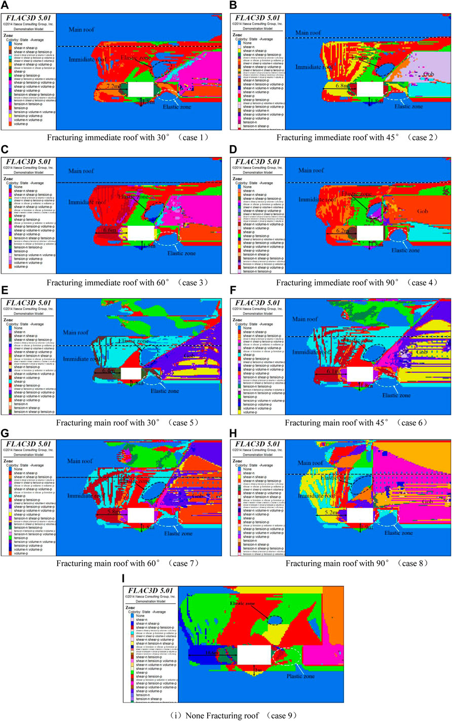
FIGURE 12. Distribution of the plastic zone in the surrounding rock of the roadway with different roof cutting schemes. (A) Fracturing the immediate roof with 30°(case 1) (B) Fracturing the immediate roof with 45° (case 2) (C) Fracturing the immediate roof with 60° (case 3) (D) Fracturing the immediate roof with 90° (case 4) (E) Fracturing the main roof with 30° (case 5) (F) Fracturing the main roof with 45° (case 6) (G) Fracturing the main roof with 60° (case 7) (H) Fracturing the main roof with 90° (case 8) (I) No fracturing of the roof (case 9).
The plastic zone distribution of the surrounding rock of the roadway in different schemes is shown in Figure 12. The widths of the plastic zone on the side of the coal rib in the immediate roof-cutting scheme are 7.2 m, 6.8 m, 6.6 m, and 6.2 m, respectively; the plastic zone in the main roof-cutting plan range is 6.4 m, 6.1 m, 5.8 m, and 5.2 m, respectively, and the plastic zone depth in the floor is 1.8 m. The above data show that the plastic zone of the coal rib in Figure 12I is the largest (10.6 m). When the main roof is cut (a, b, c, and d), the plastic zone area is significantly reduced, and the maximum reduction is about 4.4 m. Compared with the uncut top (i), the maximum reduction of the plastic zone range is 5.4 m when the immediate roof is cut (e, f, g, and h). Under the same roof-cutting angle, the plastic zone range of the coal rib in the main roof cutting is smaller than the schemes of immediate roof cutting; at the same top-cutting height, the plastic zone range of the coal rib decreases with the increase of the roof-cutting angle.
It shows that the position and area of the elastic area in the different roof-cutting schemes will vary with different roof-cutting parameters (Figure 13). The undamaged elastic area in the roof of the gob-side entry gradually moves to the top of the roadway with the increase of the roof-cutting angle; under the same roof-cutting angle, the area of the elastic area is larger in the main roof-cutting schemes. When the main roof-cutting angle is 90°, the maximum area of the elastic area in the roof is 15.02 m2, while the minimum area of the elastic area is 8.75 m2 without roof cutting, and the area of the elastic area has increased by more than 72%. Based on the above analysis, the roof-cutting plan should choose a large angle to cut the main roof. It shows that the elastic zone in the backfilling body is also different in every roof-cutting schemes
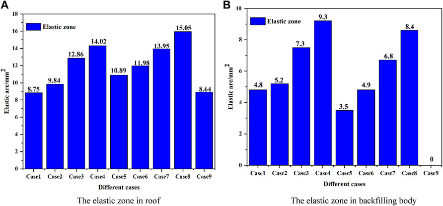
FIGURE 13. Elastic zone area in the roadway. (A) The elastic zone in the roof (B) The elastic zone in the backfilling body.
4.3.2 The Abutment Pressure Distribution
The abutment pressure distribution on the integrated coal side is shown in Figure 14; the peak abutment pressures of the nine groups of plans are 70.26, 41.19, 45.55, 47.32, 52.32, 52.64, 53.54, 58.50, and 61.55 MPa, respectively. Comparing the abutment pressure of the nine groups shows that during the 90° pre-splitting main roof cutting, the minimum peak value of the supporting pressure on the side of the integrated coal is 41.19 MPa, and the influence range of the abutment pressure is smaller. But in the roof uncut scheme, the peak abutment pressure is 72.3 MPa, and the farthest distance from the peak to the coal rib is about 5.2 m; the abutment pressure has the largest influence range, and the influence range is reduced by 1.1 m. At the same top-cutting height, the peak abutment pressure of the main roof cutting is reduced by 11.13 MPa compared with the peak pressure of the immediate roof cutting, which effectively reduces the peak stress and improves the deformation of the surrounding rock of the roadway.
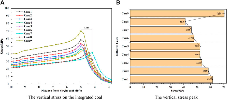
FIGURE 14. Vertical stress distribution on the integrated coal side. (A) Vertical stress on the integrated coal (B) Vertical stress peak.
4.3.3 Deformation of the Surrounding Rock of the Roadway
The deformation of the roof and the coal rib under different roof-cutting schemes is quite different, while floor heaves are very small in the different schemes (Figure 15); the deformation of the roof and the coal rib under the main roof-cutting scheme is significantly less than that of the immediate roof cutting; under the same cutting height, the deformation of the roof and integrated coal decreases with the increase of the roof-cutting angle; the maximum deformation of the roof and coal pillar side in the 90° immediate roof cutting is 48.8 and 55.4 mm, respectively, while the maximum deformation of the roof and coal pillar in the main roof cutting is 38.8 and 32.4 mm, respectively. The reason for the above phenomenon is that after only cutting the direct roof, the basic roof remains overhanging and loses the original cantilever direct roof support underneath. Therefore, the basic roof itself and the overlying strata load toward the roadway surroundings. The rock transfer produces huge pressure and bending moment force on the roadway roof, so the deformation of the roadway roof is greater than the basic roof-cutting measures.
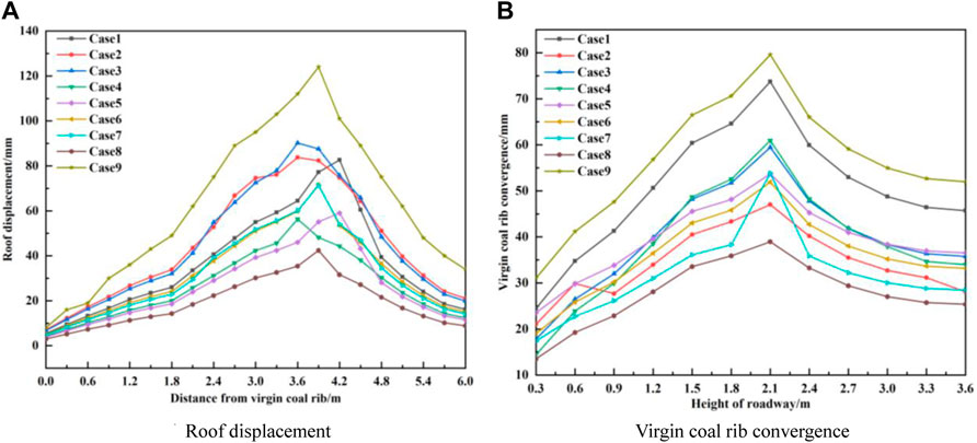
FIGURE 15. Deformation of the surrounding rock of the roadway at different angles and height of roof cutting. (A) Roof displacement (B) Virgin coal rib convergence.
Based on the above analysis, comparing the nine groups of research programs, it is found that using Option 8 to cut the top of the overlying roof rock strata along the goaf roadway has the best effect in controlling the stability of the surrounding rock, which can effectively improve the surrounding rock stress environment and reduce the plastic zone range of the surrounding rock, reducing the deformation and destruction of the surrounding rock.
5 Field Observations and Numerical Verification
Based on the results of numerical research, in the E2307 headgate, the field test of the roof-cutting technology was carried out to analyze the application effect of the technology and verify the numerical analysis results. The vertical height of the roof-cutting length is 13 m, and the roof-cutting angle is 90°; the borehole diameter is 50 mm, and the explosive charge volume parameters are the following: diameter Φ = 35 mm, l = 400 mm, and weight m = 2.56 kg. The designed blast hole spacing is 0.8 m, the charge length is 8 m, and the sealing depth is 5 m, and implement pre-splitting is 50–60 m ahead of the longwall face (Figure 16).
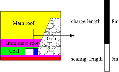
FIGURE 16. Design of roof cutting.
5.1 On-Site Measurement of Abutment Pressure and Verification of Numerical Results
To evaluate the performance of the surrounding rock mass and the newly designed roof-cutting scheme, a series of field observations, including entry convergence and stress measurement, was conducted in the E2307 headgate. The borehole stress gauge was used to measure the abutment pressure distribution in the coal pillar during the E2307 longwall face mining in order to analyze the abutment pressure distribution of the coal pillar. The strain gauges are located at 2 m, 4 m, 6 m, 8 m, 10 m, and 12 m, within the pillar with a distance of about 2 m (Figure 17). The on-site measurement result of the peak abutment pressure is 36.7 MPa, while the numerical analysis result is 39.8 MPa, with an error of 8.4%. At the same time, the on-site measurement curve of abutment pressure is consistent with the numerical analysis, so the numerical model and results are accurate and reliable, which can provide a reliable reference for the application research of this technology in similar engineering geological mines.
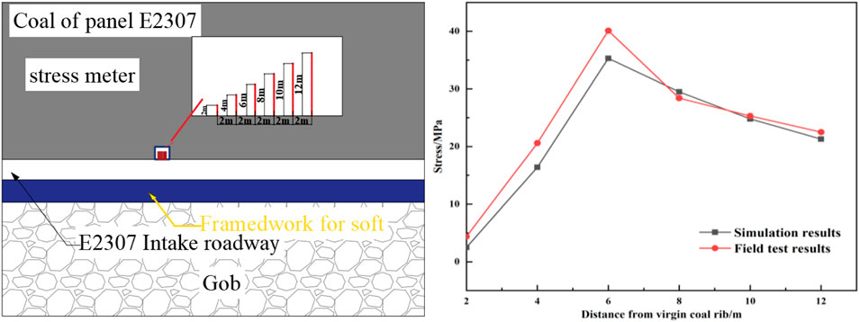
FIGURE 17. On-site measurement and numerical verification of bearing stress.
5.2 Monitoring of Convergence and Deformation of the Roadway
The convergent deformation of the surrounding rock of the E2307 headgate is monitored (Figure 18). It is observed that 50 m∼140 m of mining is the deformation acceleration period with an accumulated displacement accounting for 70% of the total. The deformation process began to slow down between the period 140 m∼200 m; the entry was basically stable after the period 140 m∼200 m. During the whole process, the maximum roof subsidence is 120 mm and the floor heave and rib-to-rib convergence are 17 and 74 mm, respectively. Observations were conducted for 2 months, and the variations of deformation of the backfilling body were monitored. The backfilling body is of large compressibility and high supporting capacity, enabling stability of the gob-side gateway (Figure 18). The above data show that the stability of the surrounding rock of the roadway is controlled after the roof-cutting technology is adopted, and the final on-site support effect is shown in Figure 18.

FIGURE 18. Deformation of the surrounding rock of the roadway.
6 Conclusion
The objective of this study was to ensure stability of the gob-side entry when experiencing quick subsidence of the hard roof, by establishing a roof-cutting mechanical model and using a numerical simulation. This study contains at least three original aspects.
1) Based on the analysis of roof cutting, a mechanical model of the roof cutting is established. The main roof-cutting technology reduces the overburden load and rotation deformation of the cantilever beam, thereby greatly reducing the load transmitted from the rock beam to the roadside backfilling body and the supporting structure in the roadway, and improves the stress environment of the roadway.
2) Taking the E2307 headgate of the Gaohe coal mine as the engineering background, the study established a numerical simulation considering strain softening and double-yield constitutive, compared and studied nine groups of roof-cutting schemes, and eventually determined that the 90° main roof cutting was adopted.
3) A new roof-cutting strategy was proposed for the E2307 headgate. Field monitoring demonstrated that this roof-cutting strategy has provided ideal stability for the E2307 headgate with a 650 m burial depth. In addition, this roof-cutting strategy provides sufficient details to allow its application in other coal mines.
Data Availability Statement
The original contributions presented in the study are included in the article/Supplementary Material, further inquiries can be directed to the corresponding author.
Author Contributions
All persons who meet authorship criteria are listed as authors, and all authors certify that they have participated sufficiently in the work to take public responsibility for the content, including participation in the concept, design, analysis, writing, or revision of the manuscript. Furthermore, each author certifies that this material or similar material has not been and will not be submitted to or published in any other publication before its appearance in the Frontiers in Earth Science. Authorship contributions Category 1: Conception and design of study: KZ; acquisition of data: KZ; and analysis and/or interpretation of data: XY, HZ, and HL. Category 2: Drafting the manuscript: KZ, CL, and HL; revising the manuscript critically for important intellectual content: CL. Category 3: Approval of the version of the manuscript to be published (the names of all authors must be listed): KZ, CL, XY, HZ, and HL.
Funding
This work was financially supported by the National Natural Science Foundation of China (No. 52074267), and the Graduate Innovation Project of Jiangsu Province(KYCX21_2366).
Conflict of Interest
The authors declare that the research was conducted in the absence of any commercial or financial relationships that could be construed as a potential conflict of interest.
Publisher’s Note
All claims expressed in this article are solely those of the authors and do not necessarily represent those of their affiliated organizations, or those of the publisher, the editors, and the reviewers. Any product that may be evaluated in this article, or claim that may be made by its manufacturer, is not guaranteed or endorsed by the publisher.
References
Bai, Q.-S., Tu, S.-H., Wang, F.-T., Zhang, X.-G., Tu, H.-S., and Yuan, Y. (2014). Observation and Numerical Analysis of the Scope of Fractured Zones Around Gateroads under Longwall Influence. Rock Mech. Rock Eng. 47 (5), 1939–1950. doi:10.1007/s00603-013-0457-9
Bai, Q., Tu, S., Wang, F., and Zhang, C. (2017). Field and Numerical Investigations of Gateroad System Failure Induced by Hard Roofs in a Longwall Top Coal Caving Face. Int. J. Coal Geology. 173, 176–199. doi:10.1016/j.coal.2017.02.015
Chen, Y., Bai, J. B., and Wang, X. Y. (2012). Support Technology Research and Application inside Roadway of Gob Side Entry Retaining. J. China Coal Soc. 37 (6), 903–910. doi:10.13225/j.cnki.jccs.2012.06.015
Han, C. L., Zhang, N., Kan, J. G., and Yuan, L. (2017). Mechanism and Application of Double Active Control with Pressure-Relieving and An-Choring for Gob-Side Entry Retaining. J. China Coal Soc. 42 (S2), 323330. doi:10.13225/j.cnki.jccs.2017.0132
Han, C. L., Zhang, N., Li, G. C., Li, B. Y., and Ha, Wu. (2013). Stability Analysis for Compound Bearing Structure of Gob-Side Entry Retaining in Large Mining Height Condition. Chin. J. Geotechnical Eng. 35 (3), 969–976. doi:10.11779/CJGE201405023
Han, C. L., Zhang, N., Yao, Y. H., Zhang, N. L., and Ji, M. (2013). Transfer Bearing Mechanism of Thick Composite Roof in Gob-Side Entry Retaining. Rock Soil Mech. 34 (S1), 318–323. doi:10.16285/j.rsm.2013.s1.040
He, M., Gao, Y., Yang, J., and Gong, W. (2017). An Innovative Approach for Gob-Side Entry Retaining in Thick Coal Seam Longwall Mining. Energies 1785, 1–22. doi:10.1002/ese3.431
He, M., Wang, Q., and Wu, Q. (2021). Innovation and Future of Mining Rock Mechanics. J. rock Mech. geotechnical Eng. 13 (1), 1–21. doi:10.1016/j.jrmge.2020.11.005
Hou, G. Y., Hu, T., Li, Z. X., Li, Z. H., Chen, J. P., and Cui, Y. K. (2019). Effect of Cutting Roof Height on the Stability of Gob-Side Retaining Roadway with Roadside Support. J. Mining Saf. Eng. 36 (5), 925–931. doi:10.13545/j.cnki.jmse.2019.05.009
Jiang, L., Zhang, P., Chen, L., Hao, Z., Sainoki, A., Mitri, H. S., et al. (2017). Numerical Approach for Goaf-Side Entry Layout and Yield Pillar Design in Fractured Ground Conditions. Rock Mech. Rock Eng. 50 (11), 3049–3071. doi:10.1007/s00603-017-1277-0
Li, Y. F., Hua, X. Z., and Cai, R. C. (2012). Mechanics Analysis on the Stability of Key Block in the Gob-Side Entry Retaining and Engineering Application. J. Mining Saf. Eng. 37 (6), 357–364. doi:10.13225/j.cnki.jccs.2012.06.015
Liu, H., Dai, J., Jiang, J., Wang, P., and Yang, J. (20192019). Analysis of Overburden Structure and Pressure-Relief Effect of Hard Roof Blasting and Cutting. Adv. Civil Eng. 2019, 1–14. Article ID 1354652. doi:10.1155/2019/1354652
Liu, J. N., He, M. C., Hou, S. L., Zhu, Z., Wang, Y. J., and Yang, J. (2021). Force Change of the Gravel Side Support during Gangue Heaping under a New Non-pillar-mining Approach. Geomechanics Eng. 27 (1), 31–43. doi:10.12989/gae.2021.27.1.031
Ma, D., Kong, S., Li, Z., Zhang, Q., Wang, Z., and Zhou, Z. (2021). Effect of Wetting-Drying Cycle on Hydraulic and Mechanical Properties of Cemented Paste Backfill of the Recycled Solid Wastes. Chemosphere 282 (10), 131163. doi:10.1016/j.chemosphere.2021.131163
Ma, X., He, M., Liu, D., He, L., and Jiang, Q. (2018). Study on Mechanical Properties of Roof Rocks with Different Cutting Inclinations. Geotech Geol. Eng. 37 (4), 2397–2407. doi:10.1007/s10706-018-00764-2
Ning, J. G., Liu, X. S., Tan, J., Gu, Q. H., Tan, Y. L., and Wang, J. (2018). Control Mechanisms and Design for a 'coal-Backfill-Gangue' Support System for Coal Mine Gob-Side Entry Retaining. Ijogct 18 (3-4), 444–466. doi:10.1504/IJOGCT.2018.093132
Shi, J. J., Ma, N. J., and Bai, Z. S. (2013). Analysis on Roof Broken Location of Gateway Retained along Goaf and Technology of Roof Support. Coal Sci. Technol. 41 (7), 35–38. doi:10.13199/j.cst.2013.07.41.shijj.011
Smart, B. G. D., and Haley, S. M. (2019). Further Development of the Roof Strata Tilt Concept for Pack Design and the Estimation of Stress Development in a Caved Waste. Int. J. Rock Mech. Mining Sci. Technol. 5, 121–130. doi:10.1016/0148-9062(87)92669-6
Tai, Y., Yu, B., Xia, B., Li, Z., and Xia, H. (2020). Research on Stress Release for the Gob-Side Roadway Using the Roof-Cutting Technology with a Chainsaw Arm. R. Soc. Open Sci. 7 (3), 191663–191680. doi:10.1098/rsos.191663
Wang, Y., Gao, Y., Wang, E., He, M., and Yang, J. (2018). Roof Deformation Characteristics and Preventive Techniques Using a Novel Non-pillar Mining Method of Gob-Side Entry Retaining by Roof Cutting. Energies 11 (3), 627–644. doi:10.3390/en11030627
Yang, H. Y., Liu, Y. B., Cao, S. G., Pan, R. K., Wang, H., Li, Y., et al. (2020). A Caving Self-Stabilization Bearing Structure of Advancing Cutting Roof for Gob-Side Entry Retaining with Hard Roof Stratum. Geomechanics Eng. 21 (1), 23–33. doi:10.12989/gae.2020.21.1.023
Yang, J., Wang, H. Y., Wang, Y. J., Gao, Y. B., Wang, J. W., and Liu, H. (2019). Fracture Characteristics of the Roof in Gob-Sdie Entry Retaining with Roof Cutting and Pressure Release. J. Mining Saf. 36 (6), 1138–1144. doi:10.13545/j.cnki.jmse.2019.06.009
Yu, B., Tai, Y., Gao, R., Yao, Q., Li, Z., and Xia, H. (2020). The Sustainable Development of Coal Mines by New Cutting Roof Technology. R. Soc. Open Sci. 7 (6), 191913–191919. doi:10.1098/rsos.191913
Zhang, B., Li, S. C., Yang, X. Y., and Zhang, D. F. (2011). Uniaxial Compression Tests on Mechanical Properties of Rock Mass Similar Material with Cross-Cracks. Rock Soil Mech. 33 (12), 3674–3679. doi:10.1007/s11783-011-0280-z
Zhang, G.-c., He, F.-l., Jia, H.-g., and Lai, Y.-h. (2017). Analysis of Gateroad Stability in Relation to Yield Pillar Size: A Case Study. Rock Mech. Rock Eng. 50 (5), 1263–1278. doi:10.1007/s00603-016-1155-1
Zhang, L., Zhao, J., Zang, C., and Wang, S. (2020). An Innovative Approach for Gob-Side Entry Retaining by Roof Cutting in Steeply Pitching Seam Longwall Mining with Hard Roof: a Case Study. Mining, Metall. Exploration 37 (8), 1079–1091. doi:10.1007/s42461-020-00219-4
Zhang, N., Han, C. L., Kan, J. G., and Z, X. G. (2014). Theory and Practice of Surrounding Rock Control for Pillarless Gob-Side Entry Retaining. J. China Coal Soc. 39 (8), 1635–1641. doi:10.13225/j.cnki.jccs.2014.9026
Zhang, N., Yuan, L., Han, C., Xue, J., and Kan, J. (2012). Stability and Deformation of Surrounding Rock in Pillarless Gob-Side Entry Retaining. Saf. Sci. 50 (4), 593–599. doi:10.1016/j.ssci.2011.09.010
Zhang, Z., Bai, J., Chen, Y., and Yan, S. (2015). An Innovative Approach for Gob-Side Entry Retaining in Highly Gassy Fully-Mechanized Longwall Top-Coal Caving. Int. J. Rock Mech. Mining Sci. 80, 1–11. doi:10.1016/j.ijrmmis.2015.09.00110.1016/j.ijrmms.2015.09.001
Keywords: pressure relief, fracturing roof, height, angle, roof cutting
Citation: Zhang K, Liu C, Zhang H, Yue X and Liu H (2022) Research on Roof Cutting Pressure Relief of the Gob-Side Entry Retaining With Roadside Backfilling. Front. Earth Sci. 10:835497. doi: 10.3389/feart.2022.835497
Received: 14 December 2021; Accepted: 19 January 2022;
Published: 09 March 2022.
Edited by:
Qingsheng Bai, Freiberg University of Mining and Technology, GermanyReviewed by:
Defu Zhu, Taiyuan University of Technology, ChinaBaobao Chen, Anhui University of Science and Technology, China
Copyright © 2022 Zhang, Liu, Zhang, Yue and Liu. This is an open-access article distributed under the terms of the Creative Commons Attribution License (CC BY). The use, distribution or reproduction in other forums is permitted, provided the original author(s) and the copyright owner(s) are credited and that the original publication in this journal is cited, in accordance with accepted academic practice. No use, distribution or reproduction is permitted which does not comply with these terms.
*Correspondence: Changyou Liu, Y3lsaXVjdW10QDE2My5jb20=