- 1No. 3 Engineering Co., Ltd., of CCCC Third Harbor Engineering Co., Ltd., Nanjing, China
- 2School of Civil Engineering, Central South University, Changsha, China
- 3Key Laboratory of Engineering Structure of Heavy Haul Railway (Central South University), Changsha, China
The blind and random use of the combined construction method may have a great impact on tunnel stability. To determine the influence of construction method conversion on tunnel deformation and the reasonable conversion condition, a numerical model is established to simulate the construction method transforms from central diaphragm method to the benching tunneling method based on Jiaoweiqin Tunnel. The conversion condition is determined based on the results of tunnel geological prediction and in-site monitoring, and the temporary two-bench tunneling method is adopted to ensure the success of construction method conversion. Besides, the parameter analysis is done to analyze the influence of mechanical properties of surrounding rock mass and bench length on tunnel stability. Research results indicate that the construction safety should be evaluated before construction method conversion is carried out by analyzing the design blueprint, tunnel geological prediction results, geological survey reports, rock mass conditions in front of tunnel face, in-site monitoring data, and numerical simulation results. Meanwhile, the construction method conversion can be carried out in the order of central diaphragm method, two-bench tunneling method, and bench tunneling method. Parameter analysis results reveal that the deformation of primary support decreases in a negative exponential form with the increase in elasticity modulus and increases approximately linearly with the increase in bench length. For shallow buried and large cross-section tunnels, the tunnel deformation is in a small state when the elastic modulus of rock mass reaches a certain value. The construction method conversion can be carried out when the rock mass has a certain stability, and the length of construction method conversion should be small to ensure construction safety.
Introduction
Stability is one of most important things in the construction of tunnels and other underground projects (Bian et al., 2017; Wang et al., 2021; Zhao et al., 2021). Affected by the complex geological conditions, the stability of surrounding rock mass may be different at different areas. To ensure tunnel stability and reduce cost, suitable excavation methods should be introduced according to the geological conditions. For example, construction methods such as the full-face excavation method and bench tunneling method can be used when the surrounding rock mass has a certain self-stability (Liang et al., 2013; Cao C. et al., 2018; Zhang et al., 2021). For the tunnel adopting the bench tunneling method, the upper section is excavated first. Once it is excavated at a certain length, the excavation of the lower section begins. This method increases the working benches, and the interference between them is small. The construction progress is fast, and it can be adopted for large-scale mechanized operation. The central diaphragm (CD) method, cross diaphragm (CRD) method, and other methods can be adopted in the case of weak surrounding rock mass (Wang et al., 2019; Chen et al., 2020). When introducing the CD or CRD method, one side of a tunnel is excavated first, then a diaphragm is constructed, and finally, the other side is excavated. The construction progress is slow because there are many construction procedures, and it is not conducive to mechanized operation.
During tunnel excavation, different construction methods will cause significant differences in the relaxation area of the surrounding rock mass and further induce the difference in the force state and deformation of the primary support. In the transition section of different construction methods, the surrounding rock mass is disturbed frequently, and the stress state in the primary support force is complicated. Improper construction schemes are likely to cause tunnel instability, which has an adverse effect on the construction. For shallow buried and large cross-section tunnels, the risk of tunnel instability during the construction method transformation cannot be ignored.
A reasonable construction scheme can effectively reduce the disturbance caused by the construction method conversion. The scheme can also reduce the construction difficulty, accelerate construction progress, and save construction costs (Cao L. et al., 2018). With the development of technology, qualitative methods are adopted to reflect the relationship between the tunnel excavation method and the geological conditions. However, there is still a lack of specific and checkable scheme for construction method conversion. Due to the complex geological conditions, some engineering accidents are likely to occur and cause huge economic losses, indicating that the choice of construction method cannot purely rely on experience.
To make up for the shortcomings of the existing research, a numerical model is established to analyze the impact of construction method conversion on the tunnel deformation based on Jiaoweiqin Tunnel. A relevant construction scheme is also proposed. The results show that the proposed scheme can ensure the success of construction method conversion. Finally, the multi-parameter analysis is done to provide reference for the construction of similar projects in the future.
Project Overview
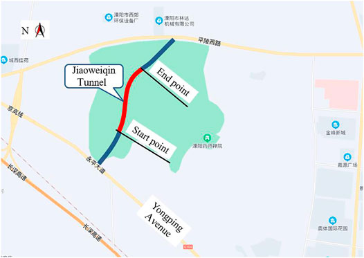
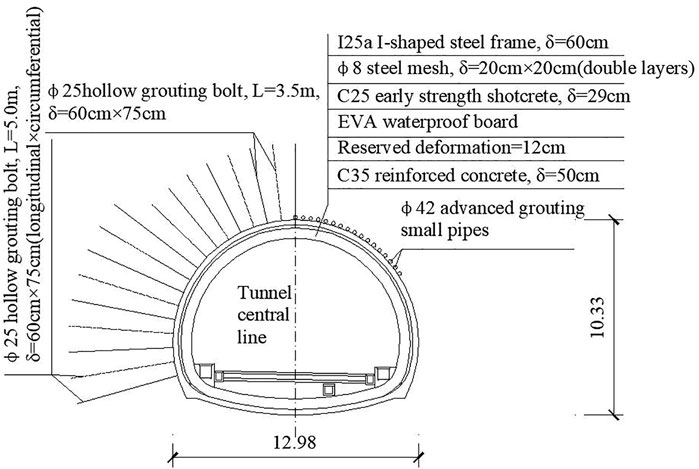
Jiaoweiqin Tunnel is located in Liyang City, Jiangsu province, China. This tunnel is a large-section and medium-length tunnel, which is about 630 m in length, 12.98 m in width, and 10.33 m in height. The maximum burial depth is about 62 m. The tunnel crosses the West Holy Mountain in the form of double separated lines. The start and end mileage of the left line is ZK0+550−ZK1+180, and that of the other line is YK0+555−YK1+180. There are mainly two construction methods, which are the CD method and the bench tunneling method. The plane layout of the tunnel and the support system are shown in Figure 1 and Figure 2, respectively.
Engineering Geology and Hydrogeology
The superficial part of West Holy Mountain is mainly artificial fill, clay, and silty clay mixed with gravel, and the underlying rock mass mainly includes andesite, siliceous shale, and limestone. There are several fault zones near the tunnel site, including the active faults in the Late Quaternary Period. Affected by the obvious geotectonic movement, the surrounding rock mass have many joints and structural planes, and the rock mass is in the range of fully weathered to medium weathered state. The core sample of the rock mass is in the shape of short columns and fragments, showing that the rock mass is full of joints and fissures. The basic quality grade is Grade V according to the Standard for Engineering Classification of Rock Mass (GB/T50218-2014, 2014).
The rainfall around the tunnel site is abundant because it is in the subtropical monsoon climate zone. The surface water is dominated by rainy season torrents, and the water volume varies greatly due to seasonal effects. The groundwater includes phreatic water, bedrock fissure water, and karst water. It mainly receives the infiltration replenishment of atmospheric precipitation and the lateral replenishment of surface water and is discharged in the form of vertical evaporation and runoff. According to the survey results, the burial depth of water is in the range of 0.25–7.60 m. Owing to the broken rock mass, there are many cracks and karst. Besides, the bedrock has good water permeability and poor water content.
Difficulty of Construction Method Conversion
Jiaoweiqin Tunnel adopts the CD method in the entrance section and needs to transform into the bench tunneling method after a certain length of excavation. However, the conversion condition is unclear. Affected by factors such as low strength of surrounding rock mass, shallow burial depth, and large cross-section, it is likely to cause tunnel instability if the construction method conversion is premature or the construction scheme is improper. On the contrary, if the construction method conversion is carried out at a later stage, it will have a greater impact on the project progress and cost.
Tunnel Deformation During Construction Method Conversion
Numerical Model
To provide reasonable guidance for the tunnel construction, FLAC3D is used to establish a numerical simulation model to analyze the deformation of primary support during the construction method conversion. This software is a three-dimensional finite difference program and has been widely used in the field of geotechnical engineering. The FLAC3D can simulate the mechanical characteristics of soil, rock, and support system (Do et al., 2014; Kabwe et al., 2020a; Kabwe et al., 2020b).
As shown in Figure 3, the stratum size is 100 m × 70 m × 73 m to eliminate the influence of boundary conditions on the calculation results, and the tunnel depth is set as 12.5 m considering that the tunnel is in the shallow buried state when the construction method conversion is carried out. For the same reason, the stress field only considers the self-weight of soil, and the tectonic stress field is ignored. In the model, the upper surface of the stratum is free; other surfaces are restrained by normal displacement. According to the construction scheme, the CD method is used first to simulate the tunnel excavation, and the bench tunneling method is adopted in the following excavation. To ensure construction safety, the conversion is composed of two stages: (1) the two-bench tunneling method and (2) the bench tunneling method. As shown in Figure 4, the numbers represent the order of excavation, and the length of each bench is 6 m.
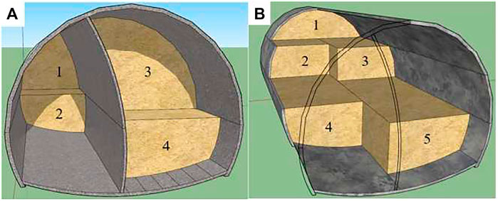
FIGURE 4. Schematic diagram of construction method conversion [(A) excavation by CD method, (B) excavation by bench tunnelling method].
In the numerical model, the stratum and primary support are connected by node coupling. To simulate tunnel excavation, the elements at the excavation area are given the null attribute. Then, the elements at the primary support area are assigned the attribute of primary support to simulate the its installation. During tunnel excavation, the surrounding rock mass will loosen and fail due to unloading and construction disturbance. The plastic state of surrounding rock mass is considered in the numerical model and simulated by the Mohr–Coulomb yield criterion. The support system is described by elastic materials. According to the geological survey data and code for design of concrete structures (GB50010-2010, 2010), the calculation parameters of the model are determined, as shown in Table 1.
Deformation of Primary Support
Figure 5 shows the deformation of primary support when the construction method conversion completed. During construction method conversion, both the vault settlement and horizontal convergence are about 10.8 mm. The small deformation of primary support indicates that the tunnel is stable, and the construction method conversion can be carried out safely. In addition, there is hysteresis in the deformation of the primary support, i.e., the maximum deformation of primary support lags the tunnel face. This is also reported by other literature (Zhao et al., 2020). It can be found that the deformation of primary support reaches the maximum at the position about 6 m behind the tunnel face.

FIGURE 5. Deformation of primary support [(A) nephogram of primary support displacement, (B) displacement evolution with the distance away from the starting position of construction method conversion].
Construction Scheme and Effects
Construction Concept
Based on the above analysis, the construction method conversion of Jiaoweiqin Tunnel can be safely carried out when the surrounding rock is stable and the bench length is 6 m, while how to determine the stability of the surrounding rock mass is an important problem during construction. It can be analyzed according to the design blueprint, tunnel geological prediction, geological survey reports, and rock mass conditions in front of the tunnel face. In addition, construction safety can be evaluated through monitoring data and numerical simulation results. Another thing that needs to be analyzed is the deformation evolution characteristics of the tunnel before and during the construction method conversion. Then, the excavation parameters can be determined. Finally, the construction method conversion can be carried out in the order of the CD method, namely, two-bench tunneling method and bench tunneling method. Figure 6 shows the flow chart for construction method conversion.
Construction Method Conversion Condition
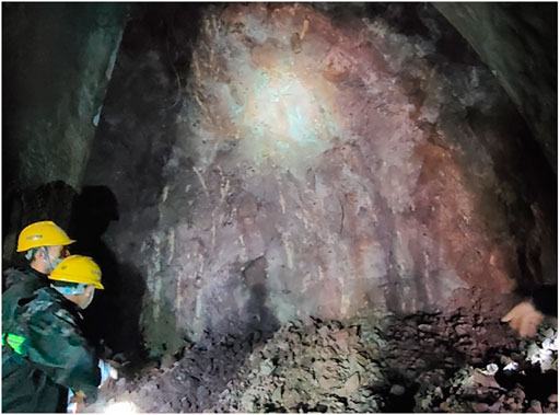
When the first part in Figure 4A is excavated to ZK0+697.4, the burial depth of the tunnel is about 11 m. The surrounding rock mass at the tunnel face is andesite. It is in moderate weathering degree and has good integrity, as shown in Figure 7. At the same time, the second, third, and fourth parts in Figure 4A are excavated at ZK0+693, ZK0+682, and ZK0+678 respectively.
To further determine the condition of the surrounding rock mass in front of tunnel face, the thickness of overlying rock mass was judged by drilling holes, and the results showed that it is not <5 m. In addition, the geological prediction results reveal that the joints and fissures in this area are not developed, as the rock mass in some area may be in broken state. According to the geological survey report, the rock mass within 100 m from the tunnel face is broken and weathered andesite. Besides, the vault settlement and convergence are stable during the demolition of vertical primary support. The overall analysis results indicate that the tunnel is in a stable state, the rock mass in front of tunnel face is in good condition, and the construction method conversion can be carried out.
Construction Method Conversion
To ensure construction safety, the distance between the invert and tunnel face should not be >40 m when the surrounding rock mass is in grade V. For this reason, during the excavation by two-bench tunneling method, the length of each bench is in the range of 3–5 m, and the excavation at the left side of the middle bench is staggered by 3–5 m. During the transition from the two-bench tunneling method to the bench tunneling method, the middle bench is excavated to be aligned with the upper bench. In this way, both the middle and the upper benches are transformed into the upper bench of the bench tunneling method. The length of the transition section here is about 5–10 m. The overall length of the transition section is 11–20 m.
As shown in Figure 4, the first part excavation stops when it excavates to the mileage of construction method conversion. The second part excavation stops if it is about 5 m away from the tunnel face of the first part. When the tunnel faces in the first part and third part are aligned, the two parts transforms into the upper and the middle benches of the two-bench excavation method in Figure 4B. The second and the fourth parts in Figure 4A are staggered by 3–5 m and excavated forward, respectively. In the case of two-bench excavation, the heights of the upper and the middle benches are 3.0 m and 3.5 m, respectively. When the tunnel is excavated by bench tunneling method, the height of the upper bench is 6.5 m.
Deformation of Primary Support
Figure 8 shows the evolution of vault settlement and horizontal convergence during the construction method conversion. It can be seen that the vault settlement and the horizontal convergence are within 12 and 10 mm, respectively, indicating that the tunnel is stable and the construction method conversion scheme is feasible. At the same time, the deviation between the field monitoring data and the numerical simulation results is within the acceptable range, indicating that the established numerical model is reliable.
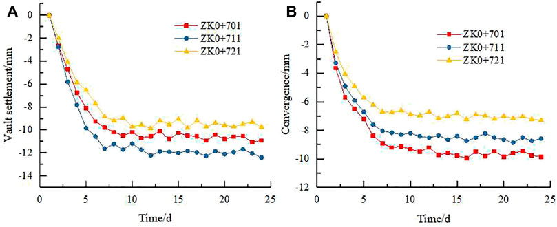
FIGURE 8. Deformation of primary support during construction method conversion [(A) vault settlement, (B) horizontal convergence].
Discussion
The geological conditions can affect the pressure acting on the primary support. When other factors are maintained, a smaller bench length is conducive to tunnel stability. To guide subsequent tunnel construction, it is necessary to analyze the influence of factors such as the mechanical properties of surrounding rock mass and the bench length.
Mechanical Properties of Surrounding Rock Mass
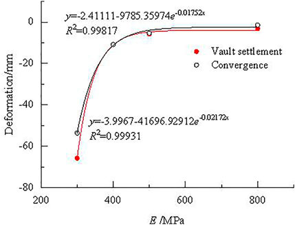
According to the Standard for Engineering Classification of Rock Mass (GB/T50218-2014 2014), the deformation modulus, internal friction angle, and cohesion of rock mass in grade V are <1.3 GPa, 27°, and 200 kPa, respectively. The deformation modulus varies greatly even though the surrounding rock mass is in the same grade. For this reason, the tunnel deformation under different deformation modulus is analyzed. Deformation modulus is a compressibility index of rock mass obtained through field load tests, i.e., the ratio of stress increment to the corresponding strain increment under partial confinement conditions. The elastic modulus is used in the numerical model. In this paper, the deformation modulus is taken as the elastic modulus, and the tunnel deformation is calculated when the elastic modulus is 300, 500, and 800 MPa, respectively, as shown in Figure 9. Figure 10 illustrates the deformation evolution of primary support with the elastic modulus. The following information can be obtained from these figures.
1) There is a certain hysteresis in the primary support deformation. In the two-bench excavation section, the maximum deformation of primary support is not located at the tunnel face but lags the tunnel face by a certain distance. As the elastic modulus of the surrounding rock mass decreases, both the distance and the deformation extent of primary support gradually increase. For example, when the elastic modulus is 300 MPa, the deformation of primary support reaches the maximum value at about 14 m behind the tunnel face. When the elastic modulus increases to 500 MPa, the distance decreases to 6 m.
2) The tunnel deformation decreases with the increase in elastic modulus, which is approximately in a negative exponential form. For shallow buried and large cross-section tunnel, when the elastic modulus is greater than a certain value, such as 400 MPa, the deformation of primary support is already in a small state. The construction method conversion will not have a major impact on tunnel stability. However, if the elastic modulus is less than this value, the deformation of primary support increases sharply, indicating that the tunnel stability is poor and there is great construction risk.
Bench Length
In this section, the bench length is set to 3, 9, and 12 m, respectively, to analyze its influence on the deformation of primary support. The deformation of primary support is shown in Figure 11. Figure 12 shows the deformation evolution of primary support with the change in bench length. The following remarks can be drawn from these figures.
1) The deformation of primary support increases approximately linearly with the increase in the bench length. As the bench length gradually increased from 3 to 12 m, the maximum deformation of primary support in the construction method conversion section gradually increased from 5.1 to 32.7 mm.
2) During the construction method conversion, a smaller bench length should be adopted to ensure construction safety. For the surrounding rock mass of grade V, there are many joints and fissures inside, and its self-bearing capacity is poor. Numerical simulation results show that the deformation of primary support increases with the increase in bench length, and the risk of surrounding rock mass instability and failure during construction also increase significantly.

FIGURE 11. Deformation of primary support under different bench length [(A) 3 m, (B) 9 m, (C) 12 m].
Conclusion
1) To ensure the success of tunnel construction method conversion, a numerical model was used to analyze the deformation of primary support during construction. From the monitoring feedback, the feasibility of the numerical model and the proposed construction scheme are validated.
2) Before the construction method conversion, the rock mass stability in front of the tunnel face should be analyzed based on the design blueprint, geological prediction, geological survey reports, and rock mass conditions in front of the tunnel face. In addition, the deformation of primary support before and during the construction method conversion should be analyzed through monitoring data and numerical model results. Finally, the construction method conversion can be carried out in the order of CD method, two-bench tunneling method, and bench tunneling method.
3) Tunnel deformation decreases in a negative exponential form with the increase in elastic modulus and increases approximately linearly with the increase in bench length. For shallow buried and large cross-section tunnel, the tunnel deformation is in a small state when the elastic modulus of the ground is greater than a certain value, and the bench length should be small to ensure construction safety.
Data Availability Statement
The original contributions presented in the study are included in the article/Supplementary Material, further inquiries can be directed to the corresponding author.
Author Contributions
ZZ: Conceptualization, methodology, software, validation, formal analysis, and writing—review and editing. CZ: Conceptualization, methodology, conceptualization, and methodology. LP: Methodology, validation, and data curation. XZ: Data curation and software. ML: Conceptualization, methodology, supervision, writing—review and editing, funding acquisition, and project administration.
Funding
Projects funded by the National Natural Science Foundation of China (Nos. 51978669, U1734208, and U1934211), Innovation-Driven Project of Central South University (No. 2020CX011), and Fundamental Research Funds for the Central Universities of Central South University (No. 2021zzts0229).
Conflict of Interest
ZZ, LP, and XZ were employed by No. 3 Engineering Co., Ltd. of CCCC Third Harbor Engineering Co., Ltd.
The remaining authors declare that the research was conducted in the absence of any commercial or financial relationships that could be construed as a potential conflict of interest.
Publisher’s Note
All claims expressed in this article are solely those of the authors and do not necessarily represent those of their affiliated organizations, or those of the publisher, the editors, and the reviewers. Any product that may be evaluated in this article, or claim that may be made by its manufacturer, is not guaranteed or endorsed by the publisher.
References
Bian, K., Liu, J., Liu, Z., Liu, S., Ai, F., Zheng, X., et al. (2017). Mechanisms of Large Deformation in Soft Rock Tunnels: a Case Study of Huangjiazhai Tunnel. Bull. Eng. Geol. Environ. 78, 431–444. doi:10.1007/s10064-017-1155-8
Cao, C., Shi, C., Lei, M., Yang, W., and Liu, J. (2018a). Squeezing Failure of Tunnels: A Case Study. Tunnelling Underground Space Technol. 77, 188–203. doi:10.1016/j.tust.2018.04.007
Cao, L., Fang, Q., Zhang, D., and Chen, T. (2018b). Subway Station Construction Using Combined Shield and Shallow Tunnelling Method: Case Study of Gaojiayuan Station in Beijing. Tunnelling Underground Space Technol. 82, 627–635. doi:10.1016/j.tust.2018.09.010
Chen, F., He, C., Li, X., and Wang, B. (2020). Construction Schemes for Shallow and Asymmetrically Loaded Tunnels Crossing below a Bridge. Int. J. Geomech. 20, 04020098. doi:10.1061/(ASCE)GM.1943-5622.0001653
Do, N.-A., Dias, D., Oreste, P., and Djeran-Maigre, I. (2014). Three-dimensional Numerical Simulation of a Mechanized Twin Tunnels in Soft Ground. Tunnelling Underground Space Technol. 42, 40–51. doi:10.1016/j.tust.2014.02.001
GB/T50218-2014 (2014). Standard for Engineering Classification of Rock Masses. Beijing: China Planning Press. (in Chinese).
GB50010-2010 (2010). Code for Design of concrete Structures. Beijing: China Architecture and Building Press. (in Chinese).
Kabwe, E., Karakus, M., and Chanda, E. K. (2020a). Creep Constitutive Model Considering the Overstress Theory with an Associative Viscoplastic Flow Rule. Comput. Geotech. 124, 103629. doi:10.1016/j.compgeo.2020.103629
Kabwe, E., Karakus, M., and Chanda, E. K. (2020b). Proposed Solution for the Ground Reaction of Non-circular Tunnels in an Elastic-Perfectly Plastic Rock Mass. Comput. Geotech. 119, 103354. doi:10.1016/j.compgeo.2019.103354
Liang, Q., Li, J., Li, D., and Ou, E. (2013). Effect of Blast-Induced Vibration from New Railway Tunnel on Existing Adjacent Railway Tunnel in Xinjiang, China. Rock Mech. Rock Eng. 46, 19–39. doi:10.1007/s00603-012-0259-5
Wang, W., Hu, M., Zhang, H., and Zhang, X. (2019). Conversion Timing of Tunnel Excavation Methods in Upper-Soft and Lower-Hard Stratum Based on Displacement Direction Angle Theory: Case Study. Int. J. Geomech. 19, 05019003. doi:10.1061/(ASCE)GM.1943-5622.0001380
Wang, F. N., Guo, Z. B., Qiao, X. B., Fan, J. Y., Li, W., Mi, M., et al. (2021). Large Deformation Mechanism of Thin-Layered Carbonaceous Slate and Energy Coupling Support Technology of NPR Anchor cable in Minxian Tunnel: A Case Study. Tunnelling Underground Space Technol. 117, 104151. doi:10.1016/j.tust.2021.104151
Zhang, H., Li, T., Du, Y., Zhu, Q., and Zhang, X. (2021). Theoretical and Numerical Investigation of Deep-Hole Cut Blasting Based on Cavity Cutting and Fragment Throwing. Tunnelling Underground Space Technol. 111, 103854. doi:10.1016/j.tust.2021.103854
Zhao, C., Peng, L., Shuai, J., Shi, C., and Lei, M. (2020). Analysis of Deformation Control for a Large- Span Metro Station Crossing Throngh Fault Zone Using Arch-Cover Method. J. Railw. Sci. Eng. 17, 1193–1200. (in Chinese). . doi:10.19713/j.cnki.43–1423/u.T20190653
Zhao, C., Lei, M., Shi, C., Cao, H., Yang, W., and Deng, E. (2021). Function Mechanism and Analytical Method of a Double Layer Pre-support System for Tunnel underneath Passing a Large-Scale Underground Pipe Gallery in Water-Rich sandy Strata: A Case Study. Tunnelling Underground Space Technol. 115, 104041. doi:10.1016/j.tust.2021.104041
Keywords: highway tunnel, stability, construction method conversion, parameter analysis, conversion condition
Citation: Zhang Z, Zhao C, Peng L, Zhang X and Lei M (2022) Research on the Stability of Shallow-Buried Large Cross-Section Tunnel by Construction Method Conversion. Front. Earth Sci. 10:831169. doi: 10.3389/feart.2022.831169
Received: 08 December 2021; Accepted: 06 January 2022;
Published: 16 February 2022.
Edited by:
Jie Han, University of Kansas, United StatesReviewed by:
Huang Zhen, Guangxi University, ChinaZhenglong Cai, China Three Gorges University, China
Copyright © 2022 Zhang, Zhao, Peng, Zhang and Lei. This is an open-access article distributed under the terms of the Creative Commons Attribution License (CC BY). The use, distribution or reproduction in other forums is permitted, provided the original author(s) and the copyright owner(s) are credited and that the original publication in this journal is cited, in accordance with accepted academic practice. No use, distribution or reproduction is permitted which does not comply with these terms.
*Correspondence: Mingfeng Lei, bWluZ2RmZW5nbGVpQGNzdS5lZHUuY24=
 Zhiyong Zhang1
 Chenyang Zhao
 Mingfeng Lei