 X. Y. Wang
 Z. Ma
Z. Ma Y. T. Zhang
- 1School of Urban Planning and Municipal Engineering, Xi’an Polytechnic University, Xi’an, China
- 2Shaanxi Provincial Department of Housing and Urban-Rural Development, Xi’an, China
- 3Xi’an Traffic Engineering Institute, Xi’an, China
Safety control of large-scale underground utility tunnels is vital for engineering management units. The establishment of early warning indicator systems and standards is critical for safety control. However, there is limited related research for engineering construction, operation, and maintenance management. Numerical analysis results of the mechanical response of the underground utility tunnel of the Xi’an Xingfu LinDai project (the largest underground urban complex in Asia) at different intersection angles and ground fissure displacements were obtained. The vertical surface settlement, structural stress, fissure displacement, and contact pressure are proposed as early warning indicators of the structure of the underground utility tunnel during the active period of a ground fissure. The safety control values and early warning standards are given based on the analysis of the results. The safety warning indicator system and standards proposed in this article are concise, practical, and easy to implement. The data sample required by this warning indicator system is small and can be obtained using conventional monitoring sensors, which can be referenced for similar projects.
Introduction
The Xi’an Xingfu LinDai Project is in Xi’an, Shaanxi Province, which is one of China’s “four ancient capitals.” It is the largest underground urban complex in Asia and the largest urban forest belt project in China. However, because the project crosses a ground fissure, which is a special geological hazard in Xi’an, the current construction faces severe technical challenges, which seriously affects the engineering construction, operation, and maintenance safety in underground utility tunnels. Several studies have revealed the genesis mechanism, distribution characteristics, and active states of ground fissures through different methods (Peng et al., 2013; Peng J. B. et al., 2016; Liu et al., 2018; Peng et al., 2018a; Peng et al., 2018b; Lu et al., 2019; Wang et al., 2019; Xu et al., 2019; Peng et al., 2020; Jia et al., 2021). At the same time, the characteristics of different soil strata also have an important influence on the activity of ground fissures (Jiang et al., 2016; Fan et al., 2019; Fan et al., 2020; Wang et al., 2020; Li et al., 2021; Wang et al., 2021a; Wang et al., 2021b; Wang et al., 2022). With the construction of an increasing number of urban underground space projects, the current research results on the prediction of the deformation law of the underground space structure during the active period of the ground fissure have been significant; however, they are mainly focused on subway tunnels (Men et al., 2011; Peng J. et al., 2016; Wang et al., 2016; Liu et al., 2017; Peng et al., 2017). Because the underground utility tunnel is part of an underground shallowly buried structure, it is different from a subway tunnel in terms of the stress field and characteristics. Therefore, it is impossible to predict the risk situation entirely based on the deformation law of the subway tunnel. Moreover, current research on underground utility tunnels is mainly focused on the response of shallowly buried structures under seismic excitation (Gomes et al., 2015; Dashti et al., 2016; Sharafi and Parsafar, 2016; Yan et al., 2021). The research on early warning management of the underground utility tunnels in the active period of a ground fissure is limited, and there is a lack of reference standards.
Standardization is a common and effective way of early warning management. Therefore, this article considers the underground utility tunnel of Xi’an Xingfu LinDai project as the research carrier. Based on the analysis results of the deformation trend of the underground utility tunnel at different intersection angles and ground fissure displacements, an early warning standard that can show the safety situation of the underground utility tunnel during the active period of ground fissures is established, so that early warning of underground utility construction in the ground fissure zone can have a “standardized” functions for the timely resolution of failures or reduced risk to disaster.
Research Carrier
Background Engineering
The Xi’an Xingfu LinDai underground utility tunnel project is the longest underground utility tunnel in China, which contains water mains, gas, rainwater, electricity, telecommunications, heat pipes, and other pipes. The underground utility tunnel project is an underground cast-in-situ reinforced concrete structure. The design uses a multi-chamber structure. The standard section is divided into a comprehensive cabin, a power cabin, and a natural gas cabin. The standard soil cover depth of the utility tunnel is approximately 4.8 m, and the standard section of the utility tunnel is 8.96 m high and 10.1 m wide.
Description of Crossing the Ground Fissure
According to the monitoring data of the surveying team of the China Earthquake Administration, there are 14 structural surface fissures in the urban area and suburbs of Xi’an. Among these, the f5 and f7 ground fissures in xi’ an pass through the Xi’an Xingfu LinDai underground utility tunnel project, and the intersection is shown in Figure 1. The eastern segment of the f5 ground fissure in Xi’an has the strongest ground fissure activity, with a maximum activity rate of up to 35 mm/a. The maximum activity rate of the ground fissure in Xi’an f7 is up to 30 mm/a, which is still active today. According to the analysis, it is believed that the vertical displacement generated by f5 and f7 fissure activities has the characteristics of long-term creep and unidirectional accumulation with time. Such long-term creep is equivalent to cumulative deformation, and it is a continuous power source for the soil around the ground fissure, which generates local stress and strain fields, eventually leading to surface soil fractures, and may have a significant impact on the underground utility tunnel.
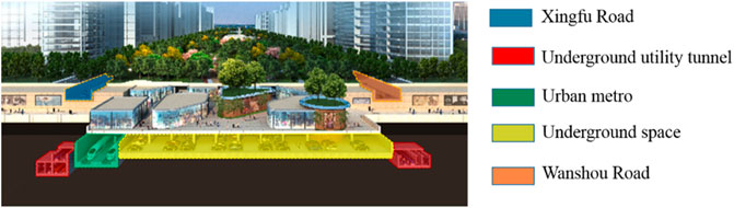
FIGURE 1. Intersection of integrated Underground utility tunnel and ground fissure.
Risk Analysis
The safety risks of the construction and operation of large underground utility tunnels in the active period of the ground fracture are mainly reflected in the following aspects:
1) Structural damage.
The vertical displacement of Xi’an ground fissures has the characteristics of long-term creep and one-way accumulation over time; therefore, as the ground fissure activity accumulates, the utility tunnel structure develops internal accumulation from the elastic stage to the plastic deformation recovery phase. When the structure is damaged, it cannot be repaired.
2) Void at the bottom of the underground utility tunnel.
Under the active environment of ground fractures, the formation pressure on the roof of the underground utility tunnel structure is relatively small and uniform, and the overall contact pressure of the upper disk increases, while the supporting effect of the surrounding rock soil at the bottom of the underground utility tunnel in the upper disk is weakened, which may lead to partial emptying.
3) Differential settlement.
When excavation or hidden excavation passes through the ground fissure zone, the working face is below the water level; concentrated water seeps along the fissure zone, thereby softening and deforming the foundation, thus causing uneven settlement of the basement. (Kang et al., 2020; Wang et al., 2021a; Wang et al., 2021b). The infiltration of water along the ground fissures may also cause local movement of the ground fissures.
4) Secondary disasters.
Because of the several pipelines inside the utility tunnel, when the local fissures are staggered to the utility tunnel through the concrete shell of the utility tunnel, the pipeline inside the utility tunnel is subjected to a certain torsion force, resulting in deformation and damage to the pipeline facilities inside the utility tunnel, causing serious secondary disasters.
Risk Prediction of Underground Utility Tunnel in the Ground Fissure Active Period
Risk prediction is the basis of early warning management, which refers to determining the short-term change trend of the early warning indicators of a project by adopting certain prediction methods (Parolai et al., 2017; Finazzi, 2020; Wang et al., 2021a; Wang et al., 2021b). In this study, a numerical simulation experiment is carried out to predict the warning trend of a large underground utility tunnel in the active period of ground fractures by taking two ground fissures at oblique crossings of the Xi’an Xingfu LinDai underground utility tunnel project, and simultaneously simulating the orthogonal crossing ground fissures.
Numerical Model Test
Parts and Meshing
The analysis uses the finite element software ABAQUS to establish a three-dimensional element model to simulate the underground utility tunnel structure under different ground fissure displacements. Because of the need to consider the displacement between the hanging wall soil and the footwall soil, and the emptiness of the utility tunnel structure and the soil, the finite element model must consider these three parts as independent, and the subsequent contact action to establish the relationship between the three parts.
In the analysis, the soil was considered as a solid element, and shell elements were used for the underground utility tunnel modeling. The type of solid element was selected as C3D8R, and the type of shell element was selected as S4R. The soil was considered as a solid element, and the hexahedron mesh was divided. The inclination angle of the ground fissure was 60°, 64°, and 90°. A schematic of the FE numerical calculation model is shown in Figure 2.

FIGURE 2. Schematic of FE numerical calculation model.
Input Parameters
The strata within the burial depth range of 50.0 m at the proposed site are from top to bottom in the following order: Miscellaneous fill, loess, paleosols, old loess, and silty clay. Because the soil in Xi’an is mainly collapsible loess, the numerical simulation parameters in this article are based on the research parameters of the soil characteristics by relevant scholars (Mei et al., 2016; Mei et al., 2019).The underground utility tunnel structure adopted C40 concrete. The specific parameters of the numerical simulation are listed in Table 1. The simulation of ground fissures in this study was realized by setting the contact between the hanging wall and the footwall soil contact surfaces. Hard contact is normally set on the soil contact surface of the hanging wall and footwall soil. The Coulomb friction model was used tangentially, a reasonable friction coefficient was set, and a limited slip between the contact surfaces was considered. The calculation model was divided into three contact bodies: 1) frictional contact between the hanging wall soil and the footwall soil; 2) friction contact between the hanging wall soil and the utility tunnel structure; 3) frictional contact between the footwall soil and the utility tunnel structure. The friction coefficient between the hanging wall soil and the footwall soil was the tangent value of the inner friction angle(φ)of loess in Table 1. The friction coefficient between the soil and the structure is the average value of the friction angle(φ) of loess and underground utility tunnel in Table 1.
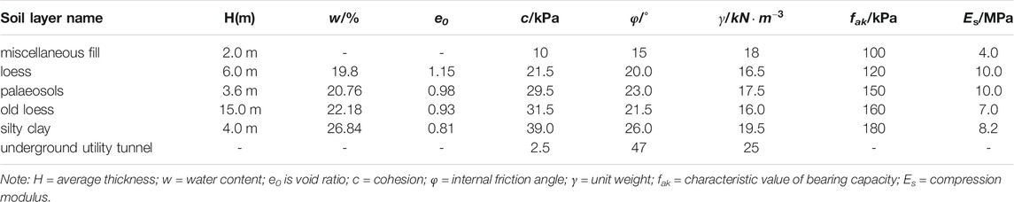
TABLE 1. Specific parameters of numerical simulation.
Numerical Analysis Conditions
The simulation of ground fissures in this paper is realized by setting the contact action between the soil contact surfaces of the upper and lower walls of the ground fissures. Hard contact is set in the normal direction of the soil contact surface of the upper and lower discs of the ground fissure, the Coulomb friction model is used in the tangent direction, a reasonable friction coefficient is set, and the limited slip between the contact surfaces is considered. The calculation model is divided into three contact bodies: 1) The frictional contact between the ground fissure hanging wall soil and the bottom wall soil, and the friction coefficient is 0.3; 2) the friction contact between the ground fissure hanging wall soil and the Underground utility tunnel, The friction coefficient is taken as 0.7; 3) The frictional contact between the bottom wall of the ground fissure and the Underground utility tunnel, the friction coefficient is taken as 0.7. The friction coefficient between the upper and lower plates is the tangent value of the internal friction angle φ of the loess in Table 1, and the friction coefficient between the soil and the structure is the average value of the tangent value of the internal friction angle φ of the loess and the Underground utility tunnel. The design life of the underground utility tunnel is 100 years, while the recommended maximum vertical dislocation quantity of Xi’an ground fissure within 100 years is 500 mm. Therefore, according to the actual situation of background engineering, this study established six kinds of analysis models for numerical calculation and analyzed deformation law of the vertical displacement of the surface, vertical displacement of the utility tunnel, the structural maximum principal stress, and the contact pressure. The numerical analysis conditions are listed in Table 2.
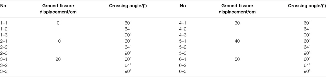
TABLE 2. Numerical analysis condition.
Analysis of Numerical Results
Deformation Law of Vertical Displacement of Surface
From Figures 3–5, the vertical displacement of the surface curve of the underground utility tunnel obliquely crossing the ground fissure (inclination 60°, 64°, and 90°). Figures 3–5, the ground fissures at three intersecting angles caused subsidence on the ground surface. The vertical displacement of the ground surface increased with an increase in ground fissure displacement. Moreover, the amount of ground surface deformation on the ground fissure was much larger than that on the ground fissure, and the uneven settlement of the ground surface near the position of the ground fissure was significant. The reason for this analysis is that the footwall remains stable, and the hanging wall continues to decline during the active period of the ground fissure. Therefore, the closer the hanging wall is to the ground fissure, the greater the rate of change of the vertical displacement of the ground surface; the farther the hanging wall is to the ground fissure, the smaller the rate of change of vertical displacement.
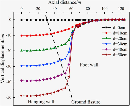
FIGURE 3. Vertical displacement of surface curve of underground utility tunnel obliquely crossing the ground fissure (inclination 60°).
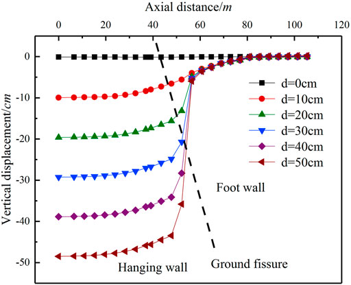
FIGURE 4. Vertical displacement of surface curve of underground utility tunnel obliquely crossing the ground fissure (inclination 64°).

FIGURE 5. Vertical displacement of surface curve of underground utility tunnel obliquely crossing the ground fissure (inclination 90°).
Deformation Law of Vertical Displacement of Utility Tunnel
From Figures 6–7, the structural deformation curve of the underground utility tunnel obliquely crossing the ground fissure (inclination 60°,64°,90°). As can be seen from Figures 6–8, at the three intersecting angles, the vertical deformation of the underground utility tunnel structure is consistent with the trend of the vertical displacement of the surface, and the whole structure is characterized by an inverse “S” curve. Moreover, the larger the amount of ground fissure displacement, the more obvious the change of the “S” curve. When the ground fissure displacement is less than 10 cm, the underground utility tunnel structure is still continuous under the three kinds of intersection angles. When the displacement is increased to 20 cm, the underground utility tunnel structure on both sides of the ground fissure begins to produce displacement. The ground fissure displacement increases to 50 cm, and the maximum displacement of the underground utility tunnel ranges from 20 to 35 cm. When the underground utility tunnel obliquely crosses to the ground fissure at 60° and 64°, the deformation gradient is more significant within the range of 20 m from the ground fissure on the hanging wall and footwall. The orthogonal ground fissure deformation gradient of the underground utility tunnel is more apparent in the range of 30 m above and 15 m below the ground fissure.
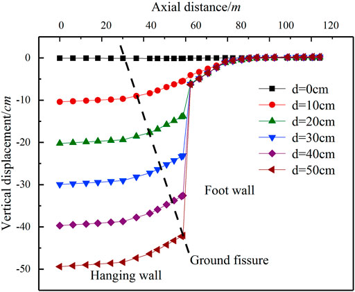
FIGURE 6. Structural deformation curve of underground utility tunnel obliquely crossing the ground fissure (inclination 60°).
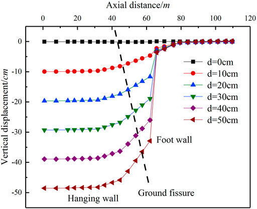
FIGURE 7. Structural deformation curve of underground utility tunnel obliquely crossing the ground fissure (inclination 64°).
FIGURE 8. Structural deformation curve of underground utility tunnel obliquely crossing the ground fissure (inclination 90°).
Deformation Law of Maximum Principal Stress
From Figures 9–11, the maximum principal stress curve of the underground utility tunnel obliquely crossed the ground fissure (inclination 60°,64°, and 90°). As can be seen from Figure 9–11, under the three intersecting angles, the positions of the maximum principal stress appeared near the ground fissures, and the maximum principal stresses were 5.346, 3.981, and 3.305 MPa, respectively. The maximum principal stress of the underground utility tunnel with an increase in the ground fissure displacement and the stress of the footwall was all greater than 0 MPa. Therefore, it was determined that when the underground utility tunnel intersects with the ground fissure, the utility tunnel structure is mainly subjected to tensile stress at the upper part and compressive stress at the lower part. Comparing Figures 9, 11, the tensile stress in the oblique condition is generally greater than the tensile stress in the orthogonal condition for the oblique condition at the same position compared with the orthogonal condition, because of the additional torsional deformation in the oblique condition.
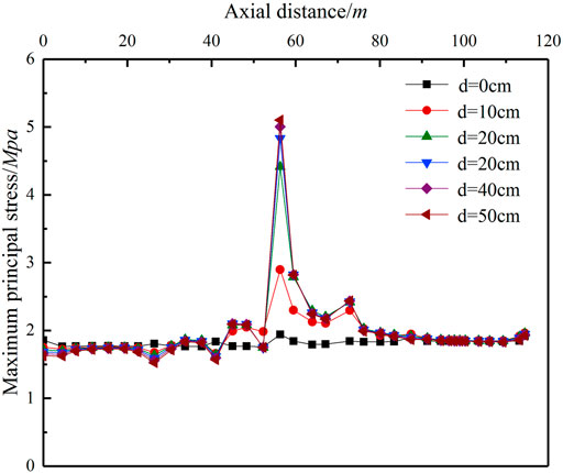
FIGURE 9. Maximum principal stress curve of underground utility tunnel obliquely crossing the ground fissure (inclination 60°).
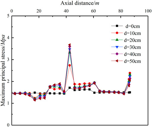
FIGURE 10. Maximum principal stress curve of underground utility tunnel obliquely crossing the ground fissure (inclination 64°).
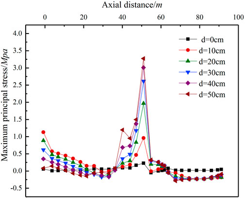
FIGURE 11. Maximum principal stress curve of underground utility tunnel obliquely crossing the ground fissure (inclination 90°).
Early Warning Standard of Underground Utility Tunnel in Ground Fiscal Active Period
Early Warning Indicator
Real-time monitoring and early warning have great significance in reducing/avoiding the consequences caused by ground fissure (Chen et al., 2021; Hoshiba, 2021; Wang and Zhao, 2021). Early warning indicator systems are generally divided into qualitative and quantitative indicators. Qualitative indicators refer to indicators that cannot be evaluated by data calculation and need to be described and analyzed objectively to reflect the evaluation results. Quantitative indicators refer to indicators that can directly obtain data, such as monitoring data. Under the environment of ground fissure activity, the underground utility tunnel structure is deformed and damaged. However, because of complex reasons for the changes in the structure of the Underground utility tunnel, it is still insufficient to formulate a single early-warning indicator as a basis for judging the safety of the underground utility tunnel structure. Moreover, quantitative early warning indicators can be directly obtained by using conventional monitoring sensors to help managers take timely control measures, which can greatly improve the early warning efficiency of operation and maintenance units. Therefore, based on the experience and knowledge of relevant experts, this article summarizes the risks in the construction of underground utility tunnels in cities, such as Xi’an, Beijing, and Zhengzhou, and lists the common risks in the early warning unit (Ding and Zhou, 2013). The following are quantitative early warning indicators, as shown in Table 3.
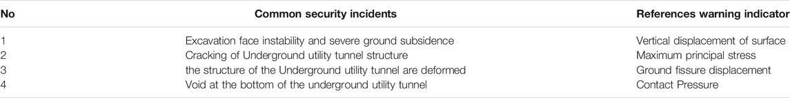
TABLE 3. Reference Early warning indicator.
Early Warning Control Value
As mentioned in the previous article, when the ground fissure is active, the main structure of the underground utility tunnel is mainly the upper tensile stress and the lower compressive stress. When the structural stress of the underground utility tunnel reaches the concrete design strength, the concrete cracks. Therefore, it is suggested that the design value of the concrete tensile strength (ft) should be used as the stress control value of the upper part of the structure, and the design value of concrete compressive strength (fc) should be used as the stress control value of the lower part of the structure. Because different underground utility tunnel heights have a certain effect on the displacement of the underground utility tunnel structure under the environment of ground fissure activity, the underground utility tunnel height of this background project is 8.96 m. When the length of the ground fracture dislocations in the three intersecting conditions reached 20 cm, the underground utility tunnel reached a height of 2.23%. The structure of the Underground utility tunnel began to shift up and down; therefore, 2.23% of the height of the underground utility tunnel was taken as the early warning control value. Because the underground utility tunnel is a shallow buried structure, the depth of soil in the underground utility tunnel has a certain effect on the amount of vertical displacement of the underground utility tunnel. According to the numerical simulation data of background engineering, when the displacement of the ground fissure is 20 cm, the utility tunnel begins to shift up and down. Therefore, it is recommended to use the maximum settlement of the ground fissure crossing position as the ground settlement early warning control value when the ground fissure displacement is 20 cm. When the ground fissure displacement is 20 cm, the maximum vertical displacements at the three angles of crossing the ground fissure are 1.931, 1.929, and 1.863 cm, respectively. Because the soil depth of the underground utility tunnel is 480 cm, it is recommended that the soil depth of the Underground utility tunnel be 0.388–0.422% as the vertical displacement of the surface value for early warning control. When the contact pressure is 0 MPa, it is used as the early warning control value when the utility tunnel structure is emptied.
Early Warning Level
The early warning control value is quantified and divided into early warning levels and corresponding intervals. The severity of the warning situation is reflected in a scientific and intuitive way, which can effectively help the decision-makers to determine reasonable decisions. Due to the different engineering geological conditions and construction environment conditions in different regions, the classification standards for early warning levels are also different (Ding and Zhou, 2013). According to relevant technical regulations, the early warning levels are divided by combining the proposed underground utility tunnel early warning indicators and control values for crossing the ground fissures, as shown in Table 4.
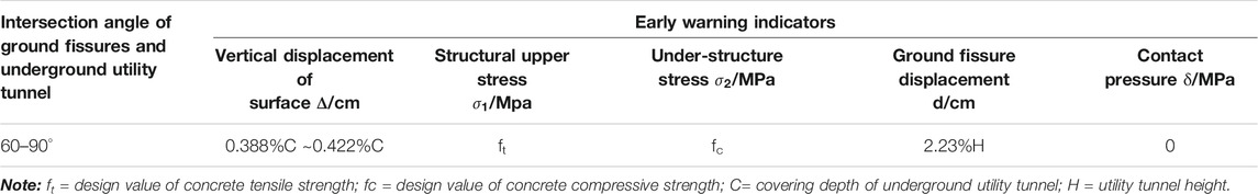
TABLE 4. Early warning control value.
Early Warning Response
When an early warning alarm is issued, all parties concerned should respond within the specified time. Generally, the first warning should respond within 3 h, the second warning within 6 h, and the third warning within 9 h. The response time can be appropriately extended; however, it must not exceed 24 h at the latest. The measures taken at different warning levels are as follows:
1) Primary warning response.
When the primary warning is reached, the construction unit, the third-party monitoring unit, and the supervision unit should strengthen the monitoring frequency of the early-warning part. The construction unit should slow down the construction speed appropriately, determine the reason for the abnormal data according to the monitoring data, and immediately formulate corresponding measures with the design unit to curb the development of risk.
2) Secondary warning response.
When the secondary warning is reached, the construction unit, the third-party monitoring unit, and the supervision unit should strengthen the monitoring frequency and on-site inspection of the warning site, and at the same time, increase the monitoring points. The construction unit shall control the construction speed, analyze the reasons according to the monitoring data, and work out corresponding measures together with the design unit to deal with it, to prevent the further development of the alarm situation and eliminate the alarm source as soon as possible.
3) Three-level warning response.
When a three-level warning is reached, the construction unit shall immediately stop the construction and report to all the units participating in the project. The construction unit shall put forward a preliminary treatment plan. Then all the parties involved in the project shall jointly hold a special early-warning meeting to formulate the early-warning disposal plan and urge the construction unit to organize and implement it immediately to eliminate potential safety risks.
Conclusion
Based on the finite element numerical simulation of the oblique crossing and orthogonal crossing of ground fissures in an underground utility tunnel, the deformation trend of the underground utility tunnel structure under the action of the ground fissures is analyzed, and an early warning standard for a large-scale underground utility tunnel during the ground fissure active period is proposed. The following conclusions can be drawn:
1) Under the three intersecting angles, the vertical deformation of the underground utility tunnel structure is basically consistent with the trend of the vertical displacement of the surface, and the entire structure is characterized by an inverse “S” curve.
2) Compared with the orthogonal condition, because of the additional torsional deformation in the diagonal condition, the tensile stress is generally greater than the orthogonal condition. When the underground utility tunnel is obliquely crossing the ground fissure, and the displacement of the ground fissure is greater than or equal to 30 cm, voids occur at the bottom of the utility tunnel structure. When the underground utility tunnel is orthogonal to the ground fissure displacement is greater than or equal to 40 cm; voids will occur at the bottom of the utility tunnel structure.
3) It is suggested that the design value of the concrete tensile strength (ft) should be used as the stress control value of the upper part of the structure, and the design value of concrete compressive strength (fc) should be used as the stress control value of the lower part of the structure; 2.23% of the height of the underground utility tunnel was taken as the early warning control value. When the contact pressure was 0 MPa, it was used as the early warning control value when the utility tunnel structure was emptied. 0.388–0.422% as the vertical displacement of surface value for early warning control.
Data Availability Statement
The original contributions presented in the study are included in the article/Supplementary Material, further inquiries can be directed to the corresponding author.
Author Contributions
ZM conceived and designed the methods, provided the guide of monitoring and theoretical research for the study, and economically supported the project. XW and YZ completed the numerical model, data analysis, and the writing of paper manuscript.
Funding
This study was supported by the Key Research and Development Project of Shaanxi Province (No. 2021SF-523).
Conflict of Interest
The authors declare that the research was conducted in the absence of any commercial or financial relationships that could be construed as a potential conflict of interest.
Publisher’s Note
All claims expressed in this article are solely those of the authors and do not necessarily represent those of their affiliated organizations, or those of the publisher, the editors and the reviewers. Any product that may be evaluated in this article, or claim that may be made by its manufacturer, is not guaranteed or endorsed by the publisher.
References
Chen, H., Li, G., Fang, R., and Zheng, M. (2021). Early Warning Indicators of Landslides Based on Deep Displacements: Applications on Jinping Landslide and Wendong Landslide, China. Front. Earth Sci. 9, 747379. doi:10.3389/FEART.2021.747379
Dashti, S., Hashash, Y. M. A., Gillis, K., Musgrove, M., and Walker, M. (2016). Development of Dynamic Centrifuge Models of Underground Structures Near Tall Buildings. Soil Dyn. Earthquake Eng. 86, 89–105. doi:10.1016/j.soildyn.2016.04.014
Ding, L. Y., and Zhou, C. (2013). Development of Web-Based System for Safety Risk Early Warning in Urban Metro Construction. Automation in Construction 34, 45–55. doi:10.1016/j.autcon.2012.11.001
Fan, J., Jiang, D., Liu, W., Wu, F., Chen, J., and Daemen, J. (2019). Discontinuous Fatigue of Salt Rock with Low-Stress Intervals. Int. J. Rock Mech. Mining Sci. 115 (3), 77–86. doi:10.1016/j.ijrmms.2019.01.013
Fan, J., Liu, W., Jiang, D., Chen, J., Tiedeu, W. N., and Daemen, J. J. K. (2020). Time Interval Effect in Triaxial Discontinuous Cyclic Compression Tests and Simulations for the Residual Stress in Rock Salt. Rock Mech. Rock Eng. 53 (9), 4061–4076. doi:10.1007/s00603-020-02150-y
Finazzi, F. (2020). The Earthquake Network Project: A Platform for Earthquake Early Warning, Rapid Impact Assessment, and Search and Rescue. Front. Earth Sci. 8, 243. doi:10.3389/feart.2020.00243
Gomes, R. C., Gouveia, F., Torcato, D., and Santos, J. (2015). Seismic Response of Shallow Circular Tunnels in Two-Layered Ground. Soil Dyn. Earthquake Eng. 75, 37–43. doi:10.1016/j.soildyn.2015.03.012
Hoshiba, M. (2021). Real-Time Prediction of Impending Ground Shaking: Review of Wavefield-Based (Ground-Motion-Based) Method for Earthquake Early Warning. Front. Earth Sci. 9, 722784. doi:10.3389/FEART.2021.722784
Jia, Z., Qiao, J., Peng, J., Lu, Q., Xia, Y., Zang, M., et al. (2021). Formation of Ground Fissures with Synsedimentary Characteristics: a Case Study in the Linfen basin, Northern china. J. Asian Earth Sci. 214 (3), 104790. doi:10.1016/j.jseaes.2021.104790
Jiang, D., Fan, J., Chen, J., Li, L., and Cui, Y. (2016). A Mechanism of Fatigue in Salt under Discontinuous Cycle Loading. Int. J. Rock Mech. Mining Sci. 86 (7), 255–260. doi:10.1016/j.ijrmms.2016.05.004
Kang, Y., Fan, J., Jiang, D., and Li, Z. (2020). Influence of Geological and Environmental Factors on the Reconsolidation Behavior of fine Granular Salt. Nat. Resour. Res. 30 (1), 805–826. doi:10.1007/s11053-020-09732-1
Li, X., Yang, S., Wang, Y., Nie, W., and Liu, Z. (2021). Macro-micro Response Characteristics of Surrounding Rock and Overlying Strata towards the Transition from Open-Pit to Underground Mining. Geofluids 2021, 1–18. doi:10.1155/2021/5582218
Liu, N., Huang, Q., Ma, Y., Bulut, R., Peng, J., Fan, W., et al. (2017). Experimental Study of a Segmented Metro Tunnel in a Ground Fissure Area. Soil Dyn. Earthquake Eng. 100, 410–416. doi:10.1016/j.soildyn.2017.06.018
Liu, N., Huang, Q., Wang, L., Fan, W., Jiang, Z., and Peng, J. (2018). Dynamic Characteristics Research of a Ground Fissure Site at Xi'an, China. Tunnelling Underground Space Technol. 82, 182–190. doi:10.1016/j.tust.2018.08.044
Lu, Q., Qiao, J., Peng, J., Liu, Z., Liu, C., Tian, L., et al. (2019). A Typical Earth Fissure Resulting from Loess Collapse on the Loess Plateau in the Weihe Basin, China. Eng. Geology. 259 (4), 105189. doi:10.1016/j.enggeo.2019.105189
Mei, Y., Hu, C.-M., Yuan, Y.-L., Wang, X.-Y., and Zhao, N. (2016). Experimental Study on Deformation and Strength Property of Compacted Loess. Geomech. Eng. 11 (1), 161–175. doi:10.12989/gae.2016.11.1.161
Mei, Y., Li, Y.-L., Wang, X.-Y., Wang, J., and Hu, C.-M. (2019). Statistical Analysis of Deformation Laws of Deep Foundation Pits in Collapsible Loess. Arab J. Sci. Eng. 44 (10), 8347–8360. doi:10.1007/s13369-019-03931-6
Men, Y. M., Zhang, J. H., and Liu, H. J. (2011). Discussion on the Computing Model for Xi’an Metro Tunnel Passing through the Ground Fissure Zone. J. Earth Sci. Environ. 33 (1), 95–100. doi:10.3969/j.issn.1672-6561.2011.01.013
Parolai, S., Boxberger, T., Pilz, M., Fleming, K., Haas, M., Pittore, M., et al. (2017). Assessing Earthquake Early Warning Using Sparse Networks in Developing Countries: Case Study of the Kyrgyz republic. Front. Earth Sci. 5, 74. doi:10.3389/feart.2017.00074
Peng, J.-b., Chen, L.-w., Huang, Q.-b., Men, Y.-m., Fan, W., and Yan, J.-k. (2013). Physical Simulation of Ground Fissures Triggered by Underground Fault Activity. Eng. Geology. 155 (14), 19–30. doi:10.1016/j.enggeo.2013.01.001
Peng, J.-b., Huang, Q.-b., Hu, Z.-p., Wang, M.-x., Li, T., Men, Y.-m., et al. (2017). A Proposed Solution to the Ground Fissure Encountered in Urban Metro Construction in Xi'an, China. Tunnelling Underground Space Technol. 61, 12–25. doi:10.1016/j.tust.2016.09.002
Peng, J. B., Sun, X. H., Wang, W., and Sun, G. C. (2016). Characteristics of Land Subsidence, Earth Fissures and Related Disaster Chain Effects with Respect to Urban Hazards in Xi'an, China. Environ. Earth Sci. 75 (16), 1–15. doi:10.1007/s12665-016-5928-3
Peng, J., Meng, L., Lu, Q., Deng, Y., and Meng, Z. (2018a). Development Characteristics and Mechanisms of the Taigu-Qixian Earth Fissure Group in the Taiyuan basin, China. Environ. Earth Sci. 77, 407. doi:10.1007/s12665-018-7570-8
Peng, J., Qu, W., Ren, J., Zhang, Q., and Wang, F. (2018b). Geological Factors for the Formation of Xi'an Ground Fractures. J. Earth Sci. 29, 468–478. doi:10.1007/s12583-018-0841-1
Peng, J., Sun, X., Lu, Q., Meng, L., He, H., Qiao, J., et al. (2020). Characteristics and Mechanisms for Origin of Earth Fissures in Fenwei basin, China. Eng. Geology. 266 (5), 105445. doi:10.1016/j.enggeo.2019.105445
Peng, J., Xu, J., Ma, R., and Wang, F. (2016). Characteristics and Mechanism of the Longyao Ground Fissure on North China Plain, China. Eng. Geology. 214 (30), 136–146. doi:10.1016/j.enggeo.2016.10.008
Sharafi, H., and Parsafar, P. (2016). Seismic Simulation of Liquefaction-Induced Uplift Behavior of Buried Pipelines in Shallow Ground. Arab J. Geosci. 9 (3), 215–227. doi:10.1007/s12517-015-2025-y
Wang, F., Peng, J., Meng, Z., Qiao, J., Wen, H., Ma, P., et al. (2019). The Origin and Impact of the Shizhuang Ground Fissure, Yingxian Area, Datong Basin, China. Eng. Geology. 261 (1), 105283. doi:10.1016/j.enggeo.2019.105283
Wang, J., Wang, T., Song, Z., Zhang, Y., and Zhang, Q. (2021a). Improved Maxwell Model Describing the Whole Creep Process of Salt Rock and its Programming. Int. J. Appl. Mech. 13 (10), 2150113 doi:10.1142/S1758825121501131
Wang, J., Wang, X., Zhang, Q., Song, Z., and Zhang, Y. (2021b). Dynamic Prediction Model for Surface Settlement of Horizontal Salt Rock Energy Storage. Energy 235, 121421. doi:10.1016/j.energy.2021.121421
Wang, J., Zhang, Q., Song, Z., Feng, S., and Zhang, Y. (2022). Nonlinear Creep Model of Salt Rock Used for Displacement Prediction of Salt Cavern Gas Storage. J. Energ. Storage 48, 103951. doi:10.1016/j.est.2021.103951
Wang, J., Zhang, Q., Song, Z., and Zhang, Y. (2020). Creep Properties and Damage Constitutive Model of Salt Rock under Uniaxial Compression. Int. J. Damage Mech. 29 (6), 902–922. doi:10.1177/1056789519891768
Wang, Z.-F., Shen, S.-L., Cheng, W.-C., and Xu, Y.-S. (2016). Ground Fissures in Xi'an and Measures to Prevent Damage to the Metro Tunnel System Due to Geohazards. Environ. Earth Sci. 75 (6), 1–11. doi:10.1007/s12665-015-5169-x
Wang, Z., and Zhao, B. (2021). Applicability of Accurate Ground Motion Estimation Using Initial P Wave for Earthquake Early Warning. Front. Earth Sci. 9, 718216. doi:10.3389/FEART.2021.718216
Xu, J., Peng, J., Deng, Y., and Wang, F. (2019). Development Characteristics and Formation Analysis of Baixiang Earth Fissure on North China plain. Bull. Eng. Geol. Environ. 78 (5), 3085–3094. doi:10.1007/s10064-018-1324-4
Keywords: ground fissure, underground utility tunnel, numerical analysis, early warning indicators, early warning standard
Citation: Wang XY, Ma Z and Zhang YT (2022) Research on Safety Early Warning Standard of Large-Scale Underground Utility Tunnel in Ground Fissure Active Period. Front. Earth Sci. 10:828477. doi: 10.3389/feart.2022.828477
Received: 03 December 2021; Accepted: 17 January 2022;
Published: 23 February 2022.
Edited by:
Junbao Wang, Xi’an University of Architecture and Technology, ChinaReviewed by:
Wencui Zhang, Henan University of Technology, ChinaFengyun Liu, Southwest Petroleum University, China
Copyright © 2022 Wang, Ma and Zhang. This is an open-access article distributed under the terms of the Creative Commons Attribution License (CC BY). The use, distribution or reproduction in other forums is permitted, provided the original author(s) and the copyright owner(s) are credited and that the original publication in this journal is cited, in accordance with accepted academic practice. No use, distribution or reproduction is permitted which does not comply with these terms.
*Correspondence: Y. T. Zhang, MTc2OTEwNTI4MDdAMTYzLmNvbQ==