- 1State Key Laboratory of Groundwater Protection and Utilization by Coal Mining, Beijing, China
- 2State Collaborative Innovation Center of Coal Work Safety and Clean-efficiency Utilization, Henan Polytechnic University, Jiaozuo, China
- 3College of Geoscience and Surveying Engineering, China University of Mining and Technology (Beijing), Beijing, China
High-strength mining has the characteristics of shallow buried depth, large mining height, and fast mining speed. Under the condition of high-strength mining, the overburden moves violently and the surface damage is serious. It has caused serious ecological security problems in the mining area. In order to solve this problem, it is necessary to adopt the technology of restoration while mining. The key to the effective implementation of this technology is to clarify the real-time distribution law and generation mechanism of surface damage. In this paper, field investigation and the theoretical analysis method are used for related research. The results show that the surface strenuous move duration is long, the strenuous move area is large, and the surface discontinuous deformation is fully developed. With the characteristics of stepped crack lags behind the location of the working face, the stepped crack spacing and periodic weighting interval are equivalent. Through discussion and analysis, it is found that the cause of serious damage is the strata movement mode of high-strength mining in “two zones” mode. Under the “two zones” mode, the roof has easy-to-slip instability, the bedrock is completely broken along the direction of the bedrock breaking angle, and the weak anti-disturbance ability of the loose layer leads to the surface becoming severely damaged. The research results can provide reference for the formulation of follow-up ecological real-time restoration measures in similar mines.
1 Introduction
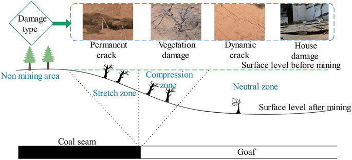
China is the largest coal producer and coal consumer in the world. Coal accounted for about 60% of China’s primary energy structure in 2019. The mining of a large number of underground coal resources brings about large-scale overburden movement and surface subsidence, which badly disturbs the original ecology and environment, and seriously affects the safe use of buildings, railways, and highways in the subsidence area. A series of economic, ecological, and environmental problems caused by mining have attracted many people’s attention (Figure 1).
At present, surface ecological restoration technology is mainly used for the treatment of surface ecological damage in the mining area, but it is usually repaired after mining. There are problems such as poor repair timeliness and low repair rate in this repair mode. In order to solve those problems, the technology of “restoration while mining” has been put forward in recent years. This technology emphasizes the timeliness and accuracy of repair, and has good application and promotion. The key to the effective implementation of this technology is to grasp the real-time distribution law of surface damage. This is also the content of this paper.
According to the mining subsidence theory (He et al., 1991; Peng, 1992; National Bureau of Coal Industry, 2017), when the ratio of mining depth to mining height is large and mining velocity is fast, the surface subsidence is generally continuous and regular in time and space. For this continuous surface subsidence, many scholars have undertaken a lot of research on its distribution law (Zhang and Chong, 2012; Cui et al., 2014; Thongprapha et al., 2015; Vervoort, 2016; Yan et al., 2018; Bai et al., 2020), generation mechanism (Wang et al., 1999; Ma et al., 2013; Yu et al., 2015; Suchowerska Iwanec et al., 2016; Salmi et al., 2017; Lian et al., 2020), prediction method (Ren et al., 1989; Ramesh and Ram, 1995; Luo and Cheng, 2009; Yan et al., 2019), and the mining-induced social and ecological problem (Bell et al., 2000; Sinha et al., 2007; Tang, 2009; Saha et al., 2011; Sasaoka et al., 2015). An abundance of research results have been obtained and some important results have been extended to the engineering application. But when the ratio of mining depth to mining height is small and the mining velocity is slow, the surface subsidence will often be accompanied by discontinuous movement, and the surface will often produce tensile cracks, stepped cracks, collapse pits, and other disasters (Fan et al., 2011; Ju and Xu, 2013; Fan et al., 2015; Yan et al., 2018; Chen et al., 2019), which will destroy the soil construction, lower the underground aquifer, reduce agricultural production, and endanger the safety of residents in the subsidence area. This highly destructive mining mode is called high-strength mining. The adverse phenomenon induced by high-strength mining can be divided into two kinds, static and dynamic. The static damage distribution law has been fully studied, and related achievements have been obtained and included in textbooks (He et al., 1991; Peng, 1992). But at present, the research results on the dynamic damage distribution law are still few and insufficient.
Under high-strength mining, the ratio of mining depth to mining height is small, the mining velocity is fast, and the above-mentioned adverse phenomenon is more serious. To deeply study the dynamic law of severe surface damage induced by high-strength mining, this paper selected working face 22,407 in the Shendong coal field, a typical high-strength mining working face, as the sample. By collecting the relevant information of working face 22,407, we studied the dynamic severe damage distribution law and analyzed its subsidence mechanism.
2 Engineering Background of Study Area
The Halagou coal mine is located in Daliuta Town, Shenmu county, Shaanxi Province, at the junction of Mu Us Desert and Loess Plateau, with an annual output of 10 million tons of coal. Working face 22,407, which belongs to the Halagou coal mine is located in the middle of panel 4. The northwest is the central return air roadway of coal seam 22, the northeast is the designed working face 22,408, the southeast is working face 22,610 designed by the Daliuta coal mine, and the southwest is the goaf of working face 22,406. The ground surface of working face 22,407 has little fluctuation and is covered by aeolian sand. Working face 407 mainly mines coal seam 22.
The coal seam within the mining range of working face 22,407 has a simple structure and is a stable coal seam. The coal seam minability index is 1. The geological structure within the minable range of the working face is simple, without the occurrence of large geological events and the existence of large geological structures.
The working face is mainly affected by the water of the Quaternary loose aquifer. The Quaternary loose aquifer is mainly composed of aeolian sand. The aquifer is 10–24 m thick and has a strong water yield. The normal water inflow of the working face is 75 m3/h.
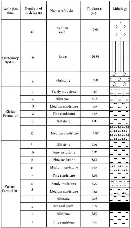
The size of working face 22,407 is 3224 m × 284 m. The bedrock thickness is 73 m, alluvium thickness is 57 m, and the aquifer thickness is 10–24 m. The average thickness, depth, and dip angle are 5.2 m, 130 m and 1°, respectively. According to the geo-mining conditions and borehole histogram of working face 22,407 (Figure 2), the lithology of the overlying strata in this working face is evaluated as medium hard. The comprehensive mechanized coal mining method is used for mining and the all caving method is used to manage the roof. The average mining velocity of working face 22,407 is 15 m/d.
From the above conditions, we can see that the ratio of mining depth to mining height of working face 22,407 is small and the mining velocity is fast. It is a typical high-strength mining face. Therefore, we chose the data of working face 22,407 to analyze the dynamic damage distribution law and reveal its generation mechanism.
3 Monitoring Methods and Data Acquisition
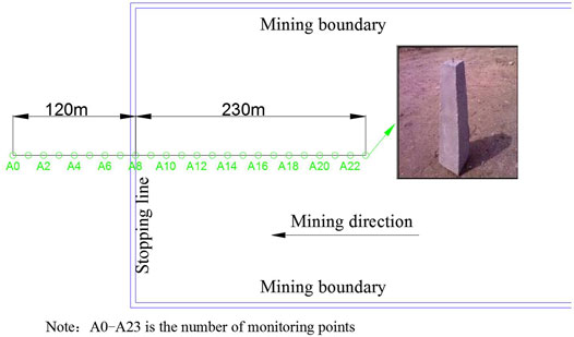
In order to obtain surface movement data, a surface movement observation station was set up on one side of the stoping line of working face 22,407 according to the mine survey regulations. The observation station included one strike surface movement observation line. The total length of the strike observation line was 350 m, with 24 monitoring points in total, and the density of monitoring points was 15 m. The point layout is shown in Figure 3.
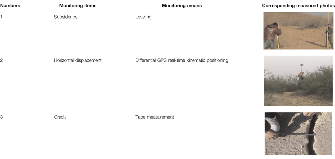
After the monitoring points were arranged, the following monitoring methods were used for data collection (Table 1).
4 Results
4.1 Surface Damage Range
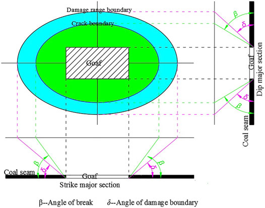
After the exploitation of underground coal resources, the area of surface mining damage was much larger than that of underground mining. According to the knowledge of mining subsidence, the angle of the damage boundary is often used to characterize the range of ground surface movement, and the angle of break is used to characterize the distribution range of surface damage, as shown in Figure 4.
The angle of the damage boundary value can be calculated with Formula (1).
Where
Where
The inclination, curvature, and horizontal movement value can be calculated with Formula (3).
Where
Through field measurement, it is found that the angle of damage boundary of working face 22,407 is 46°, and the angle of break is 70°. Compared with the angular parameters under general conditions, the corresponding angular parameters under high-strength mining conditions are small and the influence range is large.
4.2 Surface Damage Degree
The damage degree of the ground surface above the gob can be reflected by the magnitude of surface subsidence velocity. The surface subsidence velocity can be calculated by the following formula.
Where
The maximum subsidence velocity of working face 22,407 is 700 mm/d, so the surface has undergone strenuous movement and violent deformation during the mining process under the condition of high-strength mining. To analyze the dynamic distribution laws of ground surface severe damage, we evaluated two aspects: the temporal and spatial distribution characteristics of severe surface damage and the dynamic distribution laws of surface cracks.
4.2.1 Temporal Distribution of Surface Single Point Severe Damage
The surface point in the subsidence trough experiences the process from when it begins to move to the end of movement. The movement process of a surface point can be described by the subsidence velocity. The whole movement duration, according to the subsidence velocity, can be divided into three periods: initial period, active period, and weakening period (He et al., 1991; Peng, 1992; National Bureau of Coal Industry, 2017).
Initial period. From the beginning of the movement of the surface to the time when subsidence velocity reaches 1.67 mm/d or 50 mm/month.
Active period. Time interval when subsidence velocity is greater than 1.67 mm/d.
Weakening period. From the time when the movement of the surface decreases to 1.67 mm/d to the time when subsidence ends.
During these three periods, the surface points in the active period had the largest subsidence velocity and suffered the most damage. The longer the active period lasts, the more severe the damage to the surface points. The movement duration of working face 22,407 is shown in Table 2.
As can be seen from Table 2, the whole movement duration was 359 days, and the initial period, active period, and weakening period accounted for 2.5, 41.8, and 55.7% of the whole movement duration, respectively. The initial period was very short. The surface point entered the active period soon after it was affected by mining activities. The duration of the active period and weakening period was close to half of the whole movement duration. Compared with the traditional law (He et al., 1991; Peng, 1992; National Bureau of Coal Industry, 2017), it can be seen that under high-strength mining conditions, the active period was longer, and the severe damage to the surface point was more serious.
4.2.2 Spatial Distribution Law of Severe Surface Damage
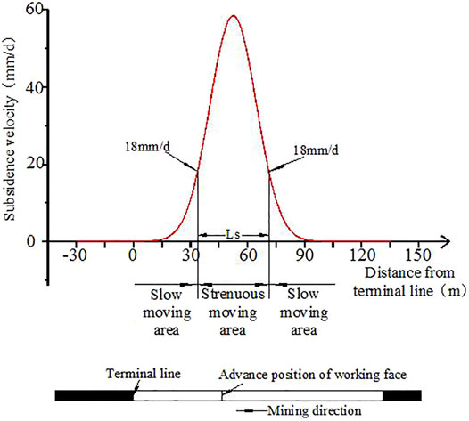
At a certain time, the subsidence velocity differed for each point on the major section of the subsidence trough. According to the subsidence velocity, its strenuous movement degree can be described by partition. A subsidence velocity of 18 mm/d was given as the critical value to define level IV damage to buildings. This paper also uses it to divide the dynamic subsidence trough into two zones (Figure 5).
Slow moving area: the surface subsidence velocity in this area is not greater than 18 mm/d; Strenuous moving area: the surface subsidence velocity in this area is larger than 18 mm/d.
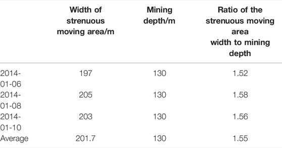
When the face advances a sufficient distance, the width of strenuous moving area reaches its maximum possible value. The field-measured width of the strenuous moving area is shown in Table 3.
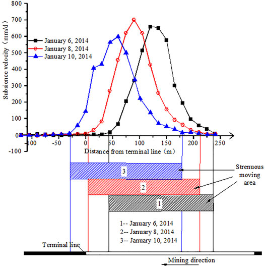
It can be seen from the above table that the strenuous moving area width was approximately 1.55 times the mining depth. That is, under high-strength mining conditions, the scope of the ground surface point moved violently and sever damages were generally large. The development of the strenuous moving area as the face advanced is shown in Figure 6.
The distance between the advanced position of the working face and the left boundary of the strenuous moving area under various advance positions of the working face measured in the Halagou coal mine are shown in Table 4.
From Table 3, the distance between the advanced position of the working face and the left boundary of the strenuous moving area for all three periods were equal to 1/5 of the strenuous moving area width. That is, the advanced position of working face was located at the left 1/5 of the strenuous moving area width.
In summary, under high-strength mining conditions, the time duration of severe damage to the surface points was relatively long, and the area where the surface was severely damaged was relatively wide. The severely damaged area was a dynamic area, which continuously moved forward as the working face advanced.
4.2.3 Surface Dynamic Crack and Its Development Rules
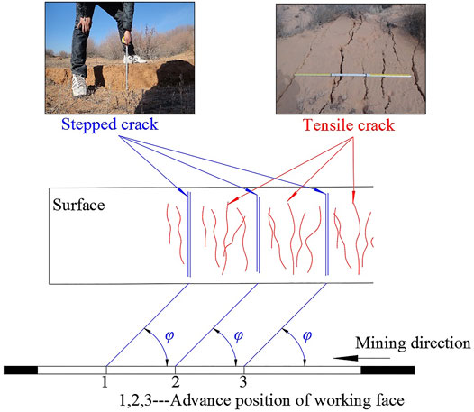
The ratio of mining depth to mining thickness of the high-strength mining working face was small and the dynamic crack was fully developed. The dynamic crack mainly had tensile cracks and stepped cracks as shown in Figure 7. The development of tensile crack had high density and small width. In addition, a stepped crack appeared in cycles.
The development of dynamic crack has the following characteristics:
1) A stepped crack lags behind the advanced position of working faces.
The overburden layer failure is developed along the direction of the bedrock fracture angle in the bedrock and along the similar vertical direction in the loose layer. The failure directly reaches to the surface and forms a stepped crack. A stepped crack lags behind the advanced position of the working face. The lag distance is called the lag distance of the stepped crack (Eq. 5), the corresponding angle is called the lag angle of the stepped crack (Eq. 6).
Where
A bedrock fracture angle of 52–57° at the side of the working face was measured (Yan et al., 2018). An average angle value of 55° was used as the bedrock fracture angle value. According to Eqs 2, 3, the lag distance of the stepped crack is 62.3 m and the lag angle of the stepped crack is 64.6°.
The field-measured lag distance of the stepped crack under various advanced positions of the working face are shown in Table 5. It can be seen from Table 5 that the calculation results are basically consistent with the field measurement results.
2) Stepped crack spacing and periodic weighting interval fairly.
The measured spacing between stepped cracks is 8–11 m along the advance direction of the working face. The periodic weighting interval is 10 m, which is basically the same as the former.
5 Discussion
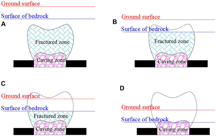
In the vertical direction, under the condition of general geological mining, after rock strata movement, the overlying strata can be divided into three different mining influence areas: caving zone, fractured zone, and sagging zone. Because the caving zone and fractured zone easily conduct water, they are jointly called the water conducting fractured zone. However, under special geological and mining conditions, the movement law of overlying strata is different, and the three mining influence zones in overburden strata do not exist at the same time. Which can be summarized as four types, as shown in Figure 8.
Type one: The “three zones” of overlying rock are fully developed. The caving zone, fractured zone, and sagging zone exist at the same time (Figure 8A).
Type two: The fracture zones directly reach the top surface of the bedrock, but do not reach the ground surface (Figure 8B).
Type three: The fracture zone directly reaches the ground surface (Figure 8C).
Type four: The caving zone directly reaches the top surface of bedrock (Figure 8D).
Under high-strength mining, the calculation formula of the height of caving zone and fracture zone is as follows (Yan et al., 2018).
Where
Through calculation, it was found that the fracture zone height of working face 22,407 was greater than the bedrock thickness. The fractured zone directly reached the surface of bedrock. Therefore, the type of overlying strata movement of the working face conformed to type two. That is to say, the type of overlying strata movement of high-strength mining was the “two zones” mode.
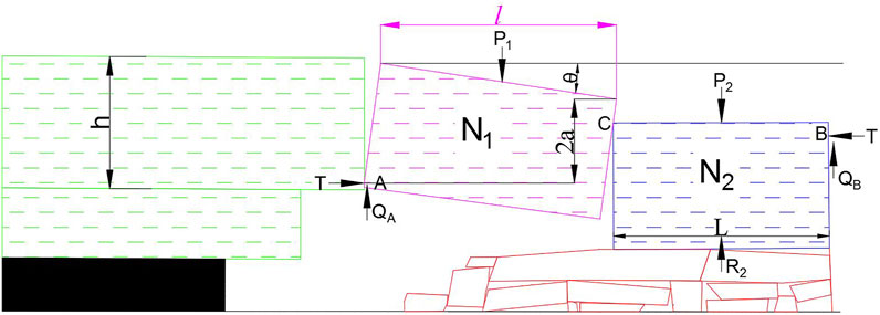
Under the “two zones” mode, the migration of the roof is shown in Figure 9.
According to the moment equilibrium, Formulas 9–12 can be derived.
Where
Since
Therefore, the relationship between the shear force and friction force of the arch foot is calculated as follows.
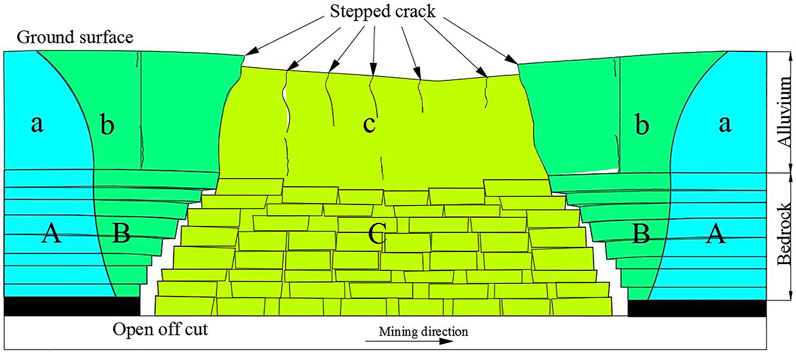
It can be seen that the sliding instability easily occurs in the “two zones” mode. The sliding instability of the roof can easily lead to the stepped subsidence of strata and induce the overburden to break in full thickness. As seen in Figure 10, because the loose layer is prone to shear failure, the stepped subsidence of strata easily leads to the formation of stepped cracks on the ground surface.
Besides, the loose layer above working face 22,407 is thick, up to 55 m. And the cohesion between particles in the loose layer such as aeolian sand is small. This will lead to the following two situations.
1) The thick loose layer is equivalent to softening of the rock stratum, which increases the influence range and degree of surface mining.
2) Due to the weak anti-disturbance ability of the loose layer, the ground surface will be seriously damaged by underground high-strength mining, and it is easy for many small irregular tension cracks to appear on the ground surface between stepped cracks (Figure 7).
6 Conclusion
Through analysis of field-measured data, the characteristics of severe surface damage induced by high-strength mining were summarized. The main conclusions are as follows:
1) Severe surface damage lasts for a long time and has a wide range. The duration of the active period is close to half of the whole movement duration. The width of the strenuous moving area is equal to 1.55 times the mining depth. The advanced position of the working face is located at the left 1/5 of the strenuous moving area width. The strenuous moving area is a dynamic area, which continuously moves forward as the working face advances.
2) The dynamic crack types of surface and their periodic distribution laws induced by high-strength mining are summarized. The development of tensile cracks has high density and small width. In addition, stepped cracks appear in cycles, and the step crack spacing and the periodic weighting interval is consistent. The surface dynamic tensile cracks reflect the surface tension process between the two roof breakages.
3) The overburden strata failure in the “step beam” model and the strata move in the “two zones” mode. The sliding instability of the roof results in stepped subsidence of rock strata and further stepped cracks on the ground surface. In addition, rock strata are completely broken, resulting in severe surface damage.
Data Availability Statement
The raw data supporting the conclusion of this article will be made available by the authors, without undue reservation.
Author Contributions
Conceptualization, WY; methodology, JC; software, WY; validation, YT and JG; formal analysis, WY; investigation, SY; resources, YY; data curation, JG; writing—original draft preparation, WY; writing—review and editing, WY; visualization, JG; supervision, YT; project administration, JC; funding acquisition, JC. All authors have read and agreed to the published version of the manuscript.
Funding
This research was funded by the Open Fund of State Key Laboratory of Water Resource Protection and Utilization in Coal Mining (grant numbers WPUKFJJ2019-20 and WPUKFJJ2019-17), the Henan Scientific and Technological Projection (grant number 212102310012), the National Natural Science Foundation of China (grant numbers U21A20108 and 51974105), the Fundamental Research Funds for the Universities of Henan Province (grant number NSFRF200314), the Youth Backbone Teacher Support Program of Henan Polytechnic University (2019XQG-07), and Doctoral Fund Program of Henan Polytechnic University (B2017-07, B2019-03).
Conflict of Interest
The authors declare that the research was conducted in the absence of any commercial or financial relationships that could be construed as a potential conflict of interest.
Publisher’s Note
All claims expressed in this article are solely those of the authors and do not necessarily represent those of their affiliated organizations, or those of the publisher, the editors and the reviewers. Any product that may be evaluated in this article, or claim that may be made by its manufacturer, is not guaranteed or endorsed by the publisher.
References
Bai, E. H., Guo, W. B., Tan, Y., Huang, G. S., Guo, M. J., and Ma, Z. B. (2020). Roadway Backfill Mining with Super-high-water Material to Protect Surface Buildings: a Case Study. Appl. Sci. 10, 107. doi:10.3390/app10010107
Bell, F. G., Stacey, T. R., and Genske, D. D. (2000). Mining Subsidence and its Effect on the Environment: Some Differing Examples. Environ. Geol. 40, 135–152. doi:10.1007/s002540000140
Chen, C., Hu, Z. Q., Wang, J., and Jia, J. T. (2019). Dynamic Surface Subsidence Characteristics Due to Super-large Working Face in Fragile-Ecological Mining Areas: A Case Study in Shendong Coalfield, China . Adv. Civ. Eng. 2019, 1–16. doi:10.1155/2019/8658753
Cui, X., Gao, Y., and Yuan, D. (2014). Sudden Surface Collapse Disasters Caused by Shallow Partial Mining in Datong Coalfield, China. Nat. Hazards 74, 911–929. doi:10.1007/s11069-014-1221-5
Fan, G. W., Zhang, D. S., and Ma, L. Q. (2011). Overburden Movement and Fracture Distribution Induced by Longwall Mining of the Shallow Coal Seam in the Shendong Coalfield. J. China Univ. Min. Tech. 40, 196–201.
Fan, L. M., Zhang, X. T., and Xiang, M. X. (2015). Characteristics of Ground Fissure Development in High-Intensity Mining Area of Shallow Seam in Yushenfu Coal Field. J. China Coal Soc. 40, 1442–1447. doi:10.13225/j.cnki.jccs.2014.1707
He, G. Q., Yang, L., and Ling, G. D. (1991). Mining Subsidence Theory. Xuzhou, China: China University of Mining and Technology Press.
Ju, J., and Xu, J. (2013). Structural Characteristics of Key Strata and Strata Behaviour of a Fully Mechanized Longwall Face with 7.0m Height Chocks. Int. J. Rock Mech. Min. Sci. 58, 46–54. doi:10.1016/j.ijrmms.2012.09.006
Lian, X., Zhang, Y., Yuan, H., Wang, C., Guo, J., and Liu, J. (2020). Law of Movement of Discontinuous Deformation of Strata and Ground with a Thick Loess Layer and Thin Bedrock in Long Wall Mining. Appl. Sci. 10, 2874. doi:10.3390/app10082874
Luo, Y., and Cheng, J. W. (2009). An Influence Function Method Based Subsidence Prediction Program for Longwall Mining Operations in Inclined Coal Seams. Min. Sci. Tech. 19, 0592–0598. doi:10.1016/s1674-5264(09)60110-1
Ma, L., Zhang, D., Sun, G., Cui, T., and Zhou, T. (2013). Thick Alluvium Full-Mechanized Caving Mining with Large Mining with Large Mining Height Face Roof Control Mechanism and Practice. J. China Coal Soc. 38, 199–203. doi:10.13225/j.cnki.jccs.2013.02.017
National Bureau of Coal Industry (2017). Pillars and Mining Reglation of Building, Water, Railway and Main Shaft and Tunnel. Beijing, China: China Coal Industry Publishing House.
Qian, M. G., Shi, P. W., and Xu, J. L. (2012). Mining Pressure and Strata Control. Xuzhou: China Uni Min Tech Pub, 374.
Ramesh, P. S., and Ram, N. Y. (1995). Prediction of Subsidence Due to Coal Mining in Raniganj Coalfield, West Bengal, India. Eng. Geol. 39, 103–111. doi:10.1016/0013-7952(94)00062-7
Ren, G., Whittaker, B. N., and Reddish, D. J. (1989). Mining Subsidence and Displacement Prediction Using Influence Function Methods for Steep Seams. Min. Sci. Technol. 8, 235–251. doi:10.1016/s0167-9031(89)90393-9
Saha, S., Pattanayak, S. K., Sills, E. O., and Singha, A. K. (2011). Under-mining Health: Environmental Justice and Mining in India. Health & Place 17, 140–148. doi:10.1016/j.healthplace.2010.09.007
Salmi, E. F., Nazem, M., and Karakus, M. (2017). The Effect of Rock Mass Gradual Deterioration on the Mechanism of Post-mining Subsidence over Shallow Abandoned Coal Mines. Int. J. Rock Mech. Min. Sci. 91, 59–71. doi:10.1016/j.ijrmms.2016.11.012
Sasaoka, T., Takamoto, H., Shimada, H., Oya, J., Hamanaka, A., and Matsui, K. (2015). Surface Subsidence Due to Underground Mining Operation under Weak Geological Condition in Indonesia. J. Rock Mech. Geotechnical Eng. 7, 337–344. doi:10.1016/j.jrmge.2015.01.007
Sinha, S., Bhattacharya, R. N., and Banerjee, R. (2007). Surface Iron Ore Mining in Eastern India and Local Level Sustainability. Resour. Policy 32, 57–68. doi:10.1016/j.resourpol.2007.06.001
Suchowerska Iwanec, A. M., Carter, J. P., and Hambleton, J. P. (2016). Geomechanics of Subsidence above Single and Multi-Seam Coal Mining. J. Rock Mech. Geotechnical Eng. 8, 304–313. doi:10.1016/j.jrmge.2015.11.007
Tang, F.-q. (2009). Research on Mechanism of Mountain Landslide Due to Underground Mining. J. Coal Sci. Eng. China 15, 351–354. doi:10.1007/s12404-009-0403-3
Thongprapha, T., Fuenkajorn, K., and Daemen, J. J. K. (2015). Study of Surface Subsidence above an Underground Opening Using a Trap Door Apparatus. Tunn. Undergr. Space Technol. 46, 94–103. doi:10.1016/j.tust.2014.11.007
Vervoort, A. (2016). Surface Movement above an Underground Coal Longwall Mine after Closure. Nat. Hazards Earth Syst. Sci. 16, 2107–2121. doi:10.5194/nhess-16-2107-2016
Wang, J. Z., Kang, J. R., and Chang, Z. Q. (1999). The Mechanism Analysis on the Dissymmetry of the Surface Subsidence Basin. J. China Coal Soc. 24, 252–255.
Yan, W., Chen, J., and Yan, Y. (2019). A New Model for Predicting Surface Mining Subsidence: the Improved Lognormal Function Model. Geosci. J. 23, 165–174. doi:10.1007/s12303-018-0008-1
Yan, W., Dai, H., and Chen, J. (2018). Surface Crack and Sand Inrush Disaster Induced by High-Strength Mining: Example from the Shendong Coal Field, China. Geosci. J. 22, 347–357. doi:10.1007/s12303-017-0031-7
Yu, B., Zhao, J., Kuang, T., and Meng, X. (2015). In Situ investigations into Overburden Failures of a Super-thick Coal Seam for Longwall Top Coal Caving. Int. J. Rock Mech. Min. Sci. 78, 155–162. doi:10.1016/j.ijrmms.2015.05.009
Keywords: severe damage, crack, dynamic distribution, high-strength mining, “two zones” mode
Citation: Yan W, Guo J, Chen J, Tan Y, Yan S and Yan Y (2022) Severe Damage Law on the Ground Surface Induced by High-Strength Mining: A Case Study From the Shendong Coal Field in China. Front. Earth Sci. 10:827826. doi: 10.3389/feart.2022.827826
Received: 02 December 2021; Accepted: 31 March 2022;
Published: 29 April 2022.
Edited by:
Wei Liu, Chongqing University, ChinaReviewed by:
R. M. Yuan, China Earthquake Administration, ChinaQiang Sun, Xi’an University of Science and Technology, China
Geng Jiabo, Jiangxi University of Science and Technology, China
Copyright © 2022 Yan, Guo, Chen, Tan, Yan and Yan. This is an open-access article distributed under the terms of the Creative Commons Attribution License (CC BY). The use, distribution or reproduction in other forums is permitted, provided the original author(s) and the copyright owner(s) are credited and that the original publication in this journal is cited, in accordance with accepted academic practice. No use, distribution or reproduction is permitted which does not comply with these terms.
*Correspondence: Junjie Chen, Y2hlbmpqQGhwdS5lZHUuY24=; Yi Tan, dGFueWlAaHB1LmVkdS5jbg==
 Weitao Yan
 Junting Guo1
 Yi Tan