- Guangzhou Metro Design and Research Institute Co. Ltd, Guangzhou, China
During a shaft and associated sprayed concrete lining (SCL) tunnel construction in a new line of Guangzhou Metro, site monitoring recorded ground surface settlement was much larger than that predicted in the design. This raised the alarm to the safety of an adjacent high-pressure gas pipe. Close-form and analytical calculations and non-coupled and coupled numerical analyses were carried out to back analyze the settlement. It was found the primary contributing factor to the excessive ground settlement is water loss-induced ground consolidation, which is commonly encountered during underground construction in south China where complex strata, such as granite residual soil and fully weathered granite, are present. This paper details the back analysis process and discusses mitigation measures that should be adopted for construction in similar ground in the future.
Introduction
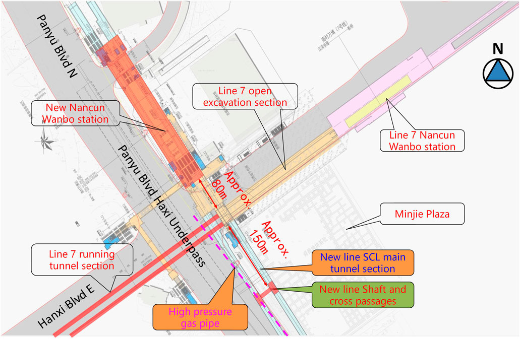
A new underground metro line is currently under construction in Guangzhou, south of China. With trains running at a maximum speed of 160 km/h, the metro line will connect Guangzhou East Railway Station in the north to Wanqingsha in the south with nine stations and a total distance of 65.3 km. NancunWanbo station, as shown in Figure 1, is to be constructed in a business area that is surrounded by high-rise commercial buildings and underground utility pipelines. A construction shaft and associated cross-passages need to be firstly constructed to facilitate the construction of a section of main tunnels using sprayed concrete lining (SCL) method. Around the shaft, there is a high-pressure gas pipe located approximately 8.0 m away from the edge of the shaft and 27.4 m above the cross-passages.
Due to site constraints, it is impossible to divert the gas pipe. Hence, extensive site monitoring was carried out for the safety of the surrounding infrastructures, including the gas pipe. It was observed during the construction that the real ground settlement was greater than the prediction and was close to the red trigger level. More importantly, there were signs that it would continue to increase and even exceed the red trigger level if no mitigation measure was to be taken.
This paper reviews the site monitoring data and investigates the reason for the excessive ground settlement. Factors influencing the excessive ground settlement are discussed, and corresponding mitigation measures are proposed. This case study provides a unique reference for underground metro construction in similar ground in the future.
Project Information
Layout of Structures
Figure 1 shows the shaft is located near an underpass junction of Panyu Blvd and Hanxi Blvd, approximately 230 m to the southeast of the new NancunWanbo station and to the southwest of adjacent Minjie Plaza that is still under construction. Sections of SCL main tunnels are to be constructed at both sides of the shaft and cross-passages. The south part of the SCL tunnels will connect to the TBM, tunnel boring machine segmental running tunnel, and the north part will first underpass the existing Line 7 tunnels before connecting to the new NancunWanbo station.
Geological Conditions
Guangzhou is located on the northern edge of the Pearl River Delta where geological and hydrological conditions are complex. Undesirable ground conditions, such as fault zones, karst caves, weathered deep grooves, and deep soft soils, are common. Geotechnical conditions could vary significantly even in close proximity, with large differences found in physical and mechanical properties. On the other hand, some records show that different rock types, including sedimentary rocks (e.g., limestone and red beds), magmatic rocks (e.g., granite), and metamorphic rocks (e.g., migmatite), coexist in one location. Such complex and composite nature in stratigraphic formation results in great difficulties in designs and constructions of underground structures in this area, especially in dealing with issues caused by the cyclic vibration of metro trains, such as reconsolidation, fatigue, residual stress, and creep (Jiang et al., 2016; Fan et al., 2019, 2020; Liu et al., 2020a; Liu et al., 2020b; Kang et al., 2020; Wang et al., 2020; Wang J. B. et al., 2021; Wang J. B. et al., 2022).
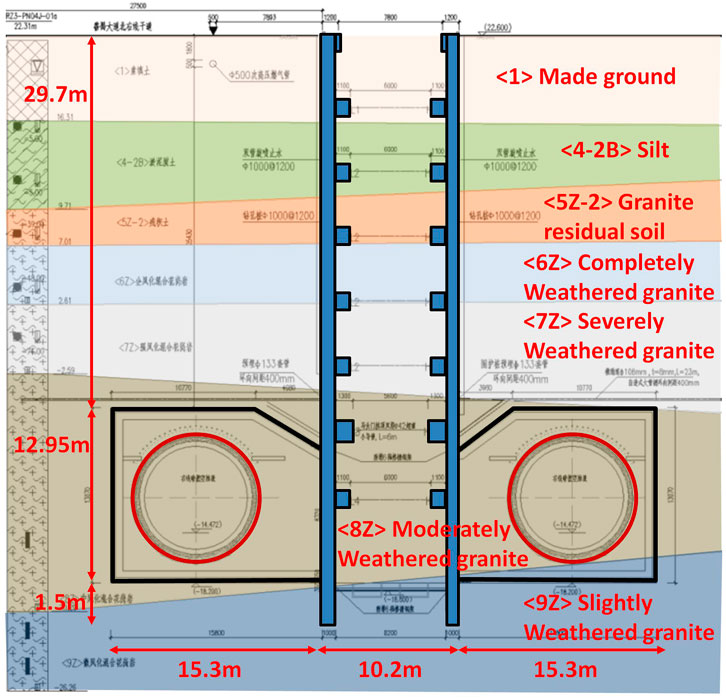
Figure 2 outlines the ground stratification of the construction shaft, cross passages, and two main SCL tunnels. The stratigraphy can be generalized as Made Ground and underneath silt overlying layers of granite which become less weathered with depth. The weathering classification follows Chinese standard “Code for geotechnical investigation of urban rail transit” (GB50307-2012-2012, 2012) in which the weathering grade generally decreases with depth, which is similar to the system defined in BS 5930:2015 (BSI 2015).
Detailed geotechnical parameters for each layer of strata are shown in Table 1. Features of these strata are described below:
1) The silt (4-2B) at shallow depth is a very soft soil with high compressibility and poor mechanical properties. It is prone to disturbance and may cause stability issue during shaft construction. The high compressibility may also result in excessive ground surface and building settlement.
2) Underneath the silt are multiple layers of granite with decreased grade of weathering with depth. The top two layers—residual soils and completely weathered granite—are widely distributed in southeast China, including Guangzhou (Rahardjo et al., 2012; Salih, 2012). Previous studies have shown that these two layers are prone to decompose with the presence of water and shear strength reduction after disturbance (Rahardjo et al., 2004; Lan et al., 2003; Wu, 2006).
3) According to the in situ soil particle analysis, the residual soil <5Z-2> is dominated by coarse particles (>0.5 mm) and fine particles (<0.005 mm), with little intermediate size particle (GZMDRI 2018). This unique composition leads to soil with both the characteristics of sand and clay but also the likelihood of piping effects.
4) Swelling potential tests were carried out for the residual soil <5Z-2>, completely weathered granite <6Z>, and severely weathered granite <7Z>. The result shows that none of these tested soil layers has significant swelling potential.
5) The lower part of the shaft was constructed in the moderately <8Z> and slightly <9Z> weathered granite layers, both of which are relatively thick without sandwiched soft soil layer. These two layers of granite have high mechanical properties and are stable with the presence of water.
Hydrogeological Conditions
During the detailed ground investigation stage at the beginning of 2018, the groundwater table was relatively stable, varying between 2.2 and 3.1 m below the ground surface level. There are typically two main aquifers in Guangzhou. The upper aquifer consists of perched water in the Made Ground <1> and pore water in the silt <4-2B> layer, which also serves as a confining layer separating the upper and lower aquifers due to its low permeability. The lower confined aquifer mainly presents in the severely <7Z> and moderately <8Z> weathered granite layers, in which a large volume of fissure water is present.
Underground Structures
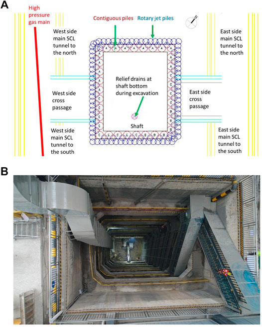
Based on the geological and hydrogeological conditions and due to the dimension of the shaft and the site constraints, contiguous pile wall with internal propping and rotary jet piles were adopted for the shaft construction, as shown in Figure 3A. The dimension of the shaft is 10.5 × 8.2 m in plan and around 43 m in depth. The contiguous piles were 1,000 mm in diameter with a spacing of 1,200 mm. Double-tube (600 mm diameter ) rotary jet piles were installed at 450 mm spacing outside of the secant pile wall to prevent the water from flowing into the shaft during its construction. Steel bar reinforced concrete wallers were constructed in 5 m vertical spacing with dimensions ranging from 1.1 × 1.1 to 1.3 × 1.5 m. The completed shaft interior view is also shown in Figure 3B.
Figure 4A shows the plan of main SCL tunnel construction, together with the cross sections of the two cross-passages on both sides of the shaft and the type C main SCL tunnel. The cross-passages are approximately 15 m long, with intrados height of 11.25 m and width of 4.4 m, respectively, as in Figure 4B. Both pipe arch and grouted tubes were installed above the excavation profile to provide additional support and improved ground conditions for the excavation. Rock bolts (25 mm diameter, 3.5 m long) are used together with the 350 mm temporary SCL primary lining to provide instant ground support immediately after the excavation. After that, sheet waterproofing membrane was installed, followed by a 500 mm thick permanent cast in situ concrete secondary lining. Steel beams were installed above and below the opening between the cross-passage and the main SCL tunnels. The main SCL tunnels were constructed from the two cross-passages towards both north and south directions, as the arrows show. Pre-grouting was carried out for the top half of the tunnel prior to the excavation at a periphery 3 m outside of the primary lining. Additional grouted tubes were installed with angle from within the tunnel for 120° of the crown. The lining systems comprise 300 mm thick temporary sprayed concrete and 400 mm thick permanent cast in situ secondary lining, as in Figure 4C. Due to the occurrence of excessive ground surface settlement, only the top heading of the type C cross section SCL tunnels were constructed prior to the investigation. The completed SCL tunnel section is highlighted in orange.
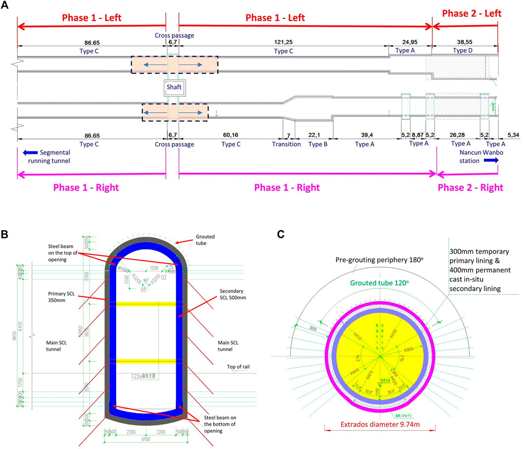
FIGURE 4. SCL tunnel construction arrangement: (A) overall plan; (B) cross section of cross passages; (C) cross section of SCL tunnel Type C.
High-Pressure Gas Pipe
A high-pressure gas pipe was identified during the desk study. The pipe is approximately 8.0 m away from the shaft pile walls, 1.8 m below the ground surface level, and 27.4 m above the cross-passage crown, as shown in Figure 5A.
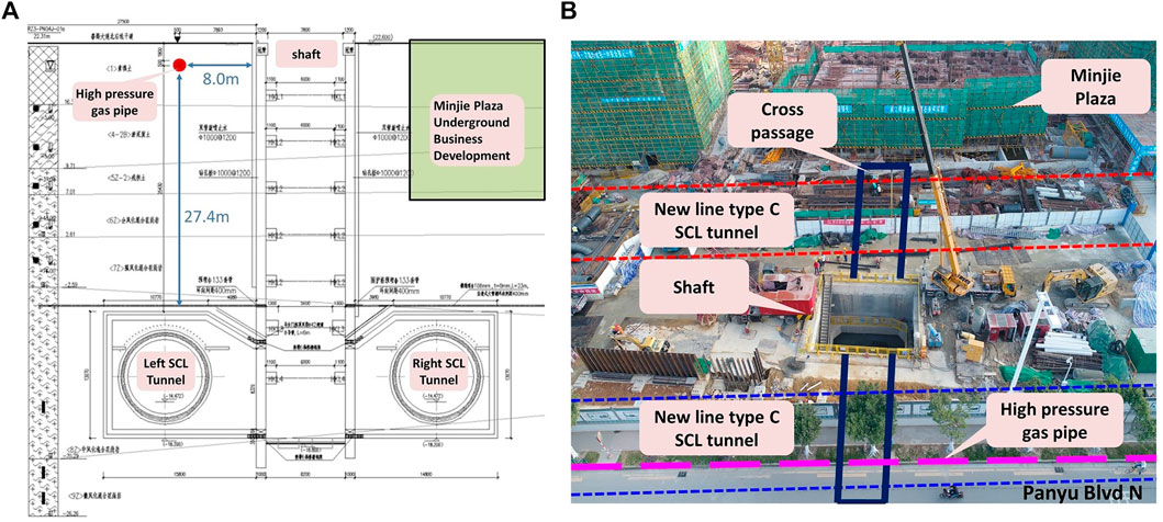
FIGURE 5. Relative location of the high-pressure gas pipe and tunnel construction: (A) drawing section; (B) construction site bird view.
The gas pipe is 500 mm in diameter and is made of 9.0 mm thick steel. As it is a critical gas supply infrastructure and is very close to the new shaft, it has been categorized as Level 1 (highest level) risk according to the Chinese standard “Risk management regulation for municipal underground metro project construction” (GB50652-2011-2011, 2012). Due to its importance and the site constraints, the diversion of this critical high-pressure gas pipe was not possible. Hence, a monitoring regime was established to closely monitor and record the deformation of the gas pipe. Contingency measures were also planned in case excessive ground settlement and pipe deformation occur. The relative location of the shaft, cross passages, main running tunnels, and the buried high-pressure gas pipe is shown in Figure 5B.
Risks and Mitigation Measures
There were two main risks associated with the construction. The first was the potential large volume of water flowing into the underground structures during the construction. As an example for the shaft and according to the closed form equation in the “Technical Specification for Retaining and Protection of Building Foundation Excavations” (JGJ 120-2012 120-2012, 2012), the maximum water inflow at the shaft base and the influence zone could be as much as 680 m3/day and 313 m, respectively. According to the Goodman analytical equation (Goodman et al., 1965), the maximum volume of water inflow per unit length could be as much as 65.5 m3/day/m.
The second risk is the potential excessive ground movement. Previous research have reported technical difficulties in controlling ground settlement for deep excavation pits (Li et al., 2021; Wang J. et al., 2021; Wang X. Y. et al., 2022). The issue becomes more complicated as detailed ground investigation report states that the groundwater table at this location varies significantly due to seasonal reasons and nearby underground constructions. The residual soil and fully and severely weathered granite are very sensitive to the presence of water. Once encountered, the ground will soften and experience large plasticity, causing excessive ground settlement that may result in excessive deformation of the high-pressure gas pipe. Hence, water-impermeable jet rotary piles were installed from the ground surface level all the way down to the crown of the cross-passages. In addition, all residual soil and fully and severely weathered granite within 3 m from the periphery of the main SCL tunnel need to be pre-grouted for watertightness. Furthermore, sleeve valve pipes were installed within 40 m periphery of the shaft and with minimum 3 m depth into the ground to allow the injection of non-shrinkage cementitious grout into silt layer if unexpected excessive ground surface settlement occurs. To control the excessive ground surface settlement, grouting using sleeve value pipes were carried out four times prior to the investigation.
Ground Movement Prediction
Based on project information above, prediction of the ground surface and the gas pipe settlement was carried out using finite element (FE) numerical analysis. The analysis shows the maximum ground surface and subsurface level at the gas pipe level is approximately 15 mm with the assumption that the groundwater is stable during the shaft construction. This complies with the maximum allowable deformation of 30 mm specified in the Chinese standard “Code for monitoring measurement for urban rail transit engineering” (GB50911-2013-2013, 2014).
Site Monitoring
Monitoring Scheme
A monitoring scheme was established to monitor the behavior of the ground and structures during the construction. The scheme is shown in Figure 6 and comprises the following items:
1) East cross-passage ground surface settlement (D series) using electronic level.
2) High-pressure gas pipe incorporating the west cross-passage ground surface settlement (G series) using electronic level.
3) Hanxi Blvd underpass ground surface settlement (S series) using electronic level.
4) Capping beam horizontal movement using total station.
5) Cross-passage lining convergence using total station.
6) Shaft pile walls horizontal movement using inclinometers.
7) Water level meter to measure the change of groundwater table.
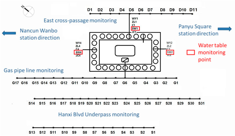
FIGURE 6. Monitoring scheme (not to scale; WY, horizontal displacement; ZL, axial force in wallers; C, pile wall inclination; SW, water table; JC, settlement).
This paper mainly focuses on the monitoring results of ground surface level (incorporating gas pipe) settlement and groundwater tables. Two levels of triggers, amber and red, were set for the ground surface level settlement. The red trigger was set as 30 mm, which is the maximum allowable ground surface settlement based on the Chinese standard aforementioned. The amber trigger was set as 24 mm, 80% of the red trigger.
Ground Surface Settlement
Figure 7A shows that large ground surface settlement exceeding 20 mm (shown in red) was recorded between monitoring points G3 and G9, adjacent to the shaft and directly above the west cross-passages. Moderate ground surface settlement between 20 and 10 mm (shown in yellow) was recorded at points parallel to and slightly away from the north and south edges of the shaft, with small ground surface settlement below 10 mm (shown in green) recorded at points further away from the shaft and cross-passage. The maximum ground surface settlement reached 27.4 mm at monitoring point G8 along the gas pipe at the north east corner, approaching the red trigger level of 30 mm. More alarmingly, the increasing trend of settlement does not show any sign of slowing, with the possibility of breach of red trigger. To control further development of ground surface and gas pipe settlement, sleeve valve pipe grouting was carried out regularly where necessary, resulting in G7 measure point malfunction.
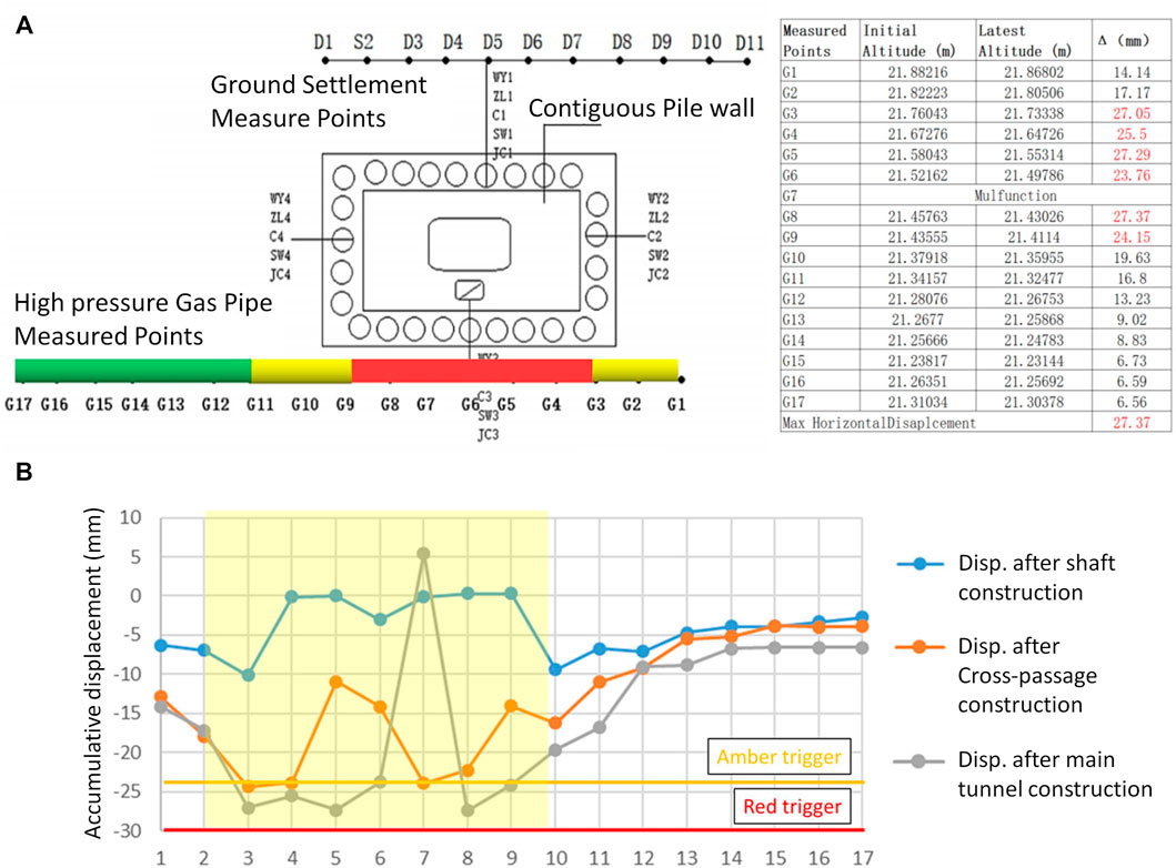
FIGURE 7. Ground surface settlement data from gas pipe monitoring: (A) latest results dated June 30, 2019; (B) change of gas pipe monitoring data over construction period (G7 malfunctioned after grouting).
Figure 7B shows the ground surface settlement along the gas pipe over three construction periods: 1) shaft construction; 2) cross-passage construction, and 3) main tunnel construction. Most settlement occurred within the cross-passage construction period, followed by the shaft construction period. Settlement was largely controlled over the main tunnel construction period after sleeve valve pipe grouting was carried out regularly. The biggest settlement occurred between monitoring points G3 and G9, which are highlighted in transparent yellow in the figure.
From site monitoring results, a clear trend can be seen in which the further a measure point is to the west cross-passage and the shaft, the smaller the ground surface settlement was recorded. No monitored settlement outside G3 and G9 exceeded 20 mm.
Water Table Drawdown
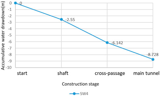
Figure 6 shows four groundwater monitoring points (SW1–SW4) were installed around the shaft, as highlighted in red box. However, only the reading of SW4 is available as the other three were damaged during the construction. The recorded SW4 groundwater table levels during the construction period up to June 30, 2019, are shown in Figure 8. The main findings are as follows:
1) The groundwater table drawdown during the shaft construction period (between November 7, 2018 and March 15, 2019, lasting 129 days) exceeded 2.5 m. This is mainly because the unsealed shaft bottom could not stop water inflow during shaft construction.
2) The drawdown during the cross-passage construction period (between March 16, 2019 and May 17, 2019, lasting 63 days) was approximately 3.6 m, greater than the previous and next stages. This is mainly attributed to the partial demolition of the water barrier jet rotary piles prior to the construction of cross-passages. Insufficient face grouting of unclosed invert during the cross-passage top heading construction also contributed to the water table drawdown.
3) The drawdown during the running tunnel period (between May 18, 2019 and June 30, 2019, lasting 44 days) is approximately 2.6 m. Following the lessons learned from the cross-passage construction, extensive non-shrinkage cementitious grouting was implemented to the whole top heading face prior to the excavation. However, water inflow is still significant, mostly attributed to the unclosed invert lining during the top heading excavation and the existence of a large number of fissures in the moderately weathered granite layers.
Other Monitoring Results
Other monitoring results, including capping beam horizontal movement and cross-passage lining convergence, were also examined. All those results were within the allowable range. The detailed results will not be presented and discussed in this paper. Only the maximum horizontal movement of the shaft wall of16.9 mm is reported here, which will be used in a later section.
Void Inspection
A void inspection was carried out. It was found that the gas pipe was in good contact with the surrounding soil and both were settled uniformly during the construction.
Discussion on Monitoring Results
With maximum reading of 27.4 mm, site monitoring results are much larger than those predicted using FE modeling without considering water loss (approximately 15 mm). Subsequent analyses concluded that the difference was caused by the water loss during the shaft, cross-passage, and main SCL tunnel construction, which in turn led to ground consolidation. In the next section, different calculation methods, including empirical, analytical closed-form equations, and FE methods, were used to confirm the governing factor in the observed excessive ground settlement.
Numerical Back Analysis
Coupled Fluid–Soil Structure Analysis
MIDAS 3D Model
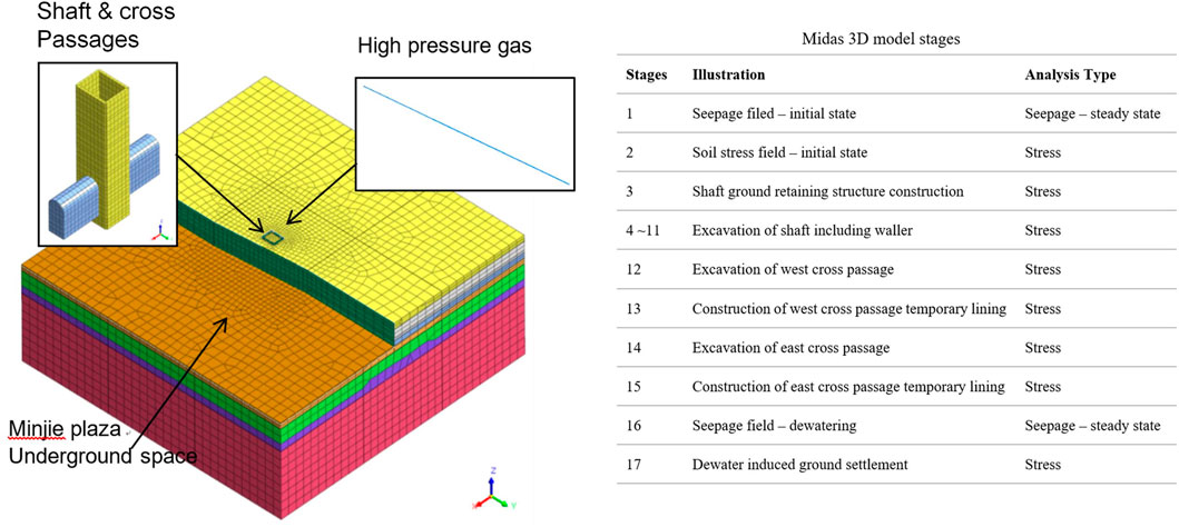
In order to confirm the reasons for the excessive ground settlement, a coupled fluid–soil structure 3D FE analysis was performed using software Midas-GTS NX, as shown in Figure 9.
The basic information of the models and key assumptions are listed below. Key structural element properties are shown below in Table 2.
1) The depth of the model is 100 m, more than twice the depth of the shaft.
2) The shaft is located at the center of the model, and the distance between the center of the shaft and each of the four boundaries is 125 m, sufficiently far to eliminate boundary effects.
3) Linear elastic beam elements were used to simulate the gas pipe and wallers.
4) Isotropic linear elastic shell elements were used to simulate the primary lining of the cross-passage and the basement side wall and base slab of MinJie plaza.
5) Orthotropic linear elastic shell elements were used to simulate the different flexural stiffness in the hoop and vertical directions of the shaft contiguous piles.
6) Volume elements were used to simulate the soil.
7) The Made Ground was simulated with linear elastic Mohr–Coulomb failure criteria.
8) The moderately and slightly weathered granite layers were simulated using linear elastic model.
9) All other layers were simulated with modified Mohr–Coulomb model.
10) The change of water table was simulated according to site monitoring data. As water drawdown has lasted for over 8 months, to save the processing time, the time-dependent transient flow was skipped. Instead, the observed maximum water table drawdown was directly simulated as quasi-steady state flow.
11) The shaft excavation, opening for the cross-passage, and the cross-passage itself were simulated sequentially by removal of soil volumes and activating structural elements.
12) To save the time of modelling, the whole length of the cross-passage was excavated in one go with a prescribed 50% ground relaxation. The remaining 50% ground pressure was relaxed after the installation of the SCL primary lining for the whole cross-passage.
MIDAS 3D Model Results
Figure 10 shows the FE analysis results. The maximum ground surface settlement is 25.4 mm, and the maximum horizontal movement of the shaft contiguous piles is 16.8 mm, both of which are very close to the site monitoring data.
Yoo (2016) pointed out two main reasons that induce ground surface settlement within water-abundant ground during an underground excavation. The first is the excavation-induced unloading effects and, hence, ground loss. The second is the water loss-induced consolidation. For the consolidation, the primary factor is the thickness and stiffness of the water-bearing layer. And the secondary factor is the initial voids ratio and permeability of the soil strata. This section justifies the water loss is the main contributing factor to the excessive ground settlement. It is noted that the sensitivity of soil geotechnical properties could cause deviation in modeling results. However, parametric studies indicate that small variations in soil properties have limited effects on analysis results and conclusions and, as a result, will not be discussed further here.
Settlement Due to Excavation
Empirical Method
Previous literature has summarized the deep excavation-induced ground movement within various ground conditions, construction methods, and support measures (Wong et al., 1997; Yoo, 2001; Leung and Charles, 2007). It was summarized that the maximum ground surface settlement is within a range of approximately 0.5–1.5 times of the maximum horizontal movement of the support structures. The monitored maximum horizontal movement of the contiguous piles recorded is 15.6 mm. Therefore, the maximum ground surface settlement solely caused by excavation should be between 7.8 and 23.4 mm, which is less than the observed maximum value of 27.4 mm. The average value of the results obtained from empirical method is 15.6 mm.
Analytical Method
This section investigates the ground loss using closed-form equations.
The ground surface settlement can be calculated using the following equation (Liu et al., 2015)
in which, Sw is the total displaced area of the supporting structure; xi is the distance between the calculation point to the boundary of the deep excavation; Hg is the total depth of the support structure, equal to 42.5 m; φ is the average internal friction angle of the strata which the structure is supporting, equal to 23°; and Δδ is the average value of horizontal movements at the top and bottom of the support structure, equal to 0.057 mm according to monitoring.
Substituting numbers into the equations, it can be calculated that the total settlement of the ground, Sw, is equal to 30.7 m2 and X0 equals 28.1 m. Hence, the maximum ground surface settlement is about 13.5 mm. This is close to the average value of the maximum ground surface settlement of 15.6 mm obtained from the empirical method as described in the previous section.
Settlement Due to Water Loss—Analytical Method
Following the one-dimensional consolidation theory (Xu et al., 2014; Liu et al., 2015), the ground surface settlement can be attributed to the drawdown of the groundwater level and the increased effective stress and strain of the soil skeleton, following the equation:
in which en is the initial void's ratio of each of the ground strata; Hi is the thickness of each of the ground strata; ΔPi is the groundwater variation-induced effective stress of the soil skeleton; and a0.1-0.2 is the compression index.
Where soil deformation moduli are obtained directly from site measurements, the calculation equation could be revised to:
in which E0,i is the soil deformation modulus of each of the ground strata.
For initial estimations, Equation 5 could be further revised to:
in which ΔPave is the average groundwater variation-induced effective stress of the soil skeleton; Pbtm is the groundwater variation-induced effective stress at final water lever; and Eave is the average deformation modulus.
Assuming the gradient of groundwater variation is linear, with maximum water loss at the center of the shaft from site monitoring data and zero water loss at the boundary of the influence zone, the maximum ground surface settlements Δs and Δini are calculated as 30.6 and 29.9 mm, respectively. The calculation process of Δs is shown in Table 3 as below.
Deformation of Gas Pipe–Analytical Method
Assuming there is no relative movement along the pipeline longitudinal direction between the soil body and gas pipe, the settlement of the gas pipe can be calculated based on coefficient of soil transfer (CST) (Liu et al., 2015), which is the ratio between the settlement of the investigated depth and that of the ground surface:
in which
y = distance between the investigated location and the pit edge, which is 8.0 m for this case
z = distance between the investigated depth and the ground surface, which is 1.8 m for this case.
B = width of pit excavation, which is 8 m for this case.
Substituting the numbers into the equation, CST is calculated as 0.94. This means the settlement of the gas pipe is very close to that at ground surface level.
Finite Element Validation
Further FE analysis was carried out to confirm the settlement results obtained from empirical and analytical calculations presented in previous sections.
As shown in Figure 11A, for the case with only shaft excavation but without loss of water, the maximum ground surface settlement and contagious pile horizontal movement are 14.3 and 15.8 mm, respectively. For the case with only loss of water but without shaft excavation, the maximum ground surface settlement and contagious pile horizontal movement are 24.7 and 0.1 mm, respectively. The analysis results also show that the settlement of the gas pipe is 20.5 mm, close to the ground surface settlement, as in Figure 11B.
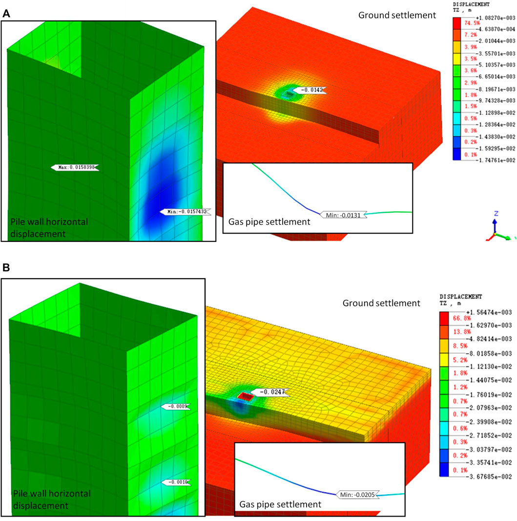
FIGURE 11. Finite element analysis results: (A) shaft excavation but without loss of water; (B) only loss of water but without shaft excavation.
Discussion of Results
Table 4 shows the coupled analysis results are not the sum of the results from the excavation only case and the water loss only case. Instead, it is closer to the loss of water only case results. It is an important conclusion that the loss of water is the primary ground risk and the underground structure excavation is a secondary risk in such water-abundant ground.
Table 4 also shows that, regarding maximum ground surface settlement, maximum horizontal movement of pile walls, and maximum gas pipe settlement/CST, good agreements were found between analytical calculations, coupled FE analyses, and site monitoring. It is therefore reasonable to conclude that fully coupled flow analysis and analytical method could be used to estimate structural effects caused by groundwater loss where applicable.
Mitigation Measures for Future Projects
Calculations presented in Section 4 confirmed that in this case the primary contributing factor to the excessive ground surface settlement was the water loss-induced consolidation. The original passive protection measure using sleeve valve pipe grouting prevents only the short-term ground settlement. Its effect diminishes over time unless grouting is carried out regularly, which is both time-consuming and costly. This is reflected by the further large ground surface settlement during the main SCL tunnel top heading construction after previous three times sleeve valve pipe grouting during the cross-passage construction. Without any other active mitigation measure, further ground settlement will be envisaged to occur during future construction (Liang et al., 2020) and cause greater engineering difficulties. Therefore, preventative measures should be adopted to maintain the groundwater level and improve the ground stiffness through ground treatment. This section discusses possible measures.
Pressurized Recharge
Considering the severity of the water loss on site, it is necessary to adopt pressurized recharge to avoid further consolidation during the subsequent construction. Due to the presence of impermeable layers of silt <4-2B> and granite residual soil <5Z>, the minimum recharging level should reach the boundary between completely weathered granite <6Z> and severely weathered granite <7Z>. The recharge pressure should be between 0.2 and 0.3 MPa. The sanity quality of the recharged water should be slightly better than the original groundwater to avoid contamination.
Grouting
Table 3 shows the water loss mostly occurred in the strata of silt <4-2B>, granite residual soil <5Z>, and completely weathered granite <6Z>, which account for approximately 70% of the total water loss. Therefore, grouting can be used to improve the stiffness of the strata above the completely weathered granite <6Z>. Grouting could be extended to severely weathered granite <7Z> if ground settlement has already been severe.
Monitoring
During the writing of this paper, the deformation of the high-pressure gas pipe is already close to the maximum allowable deformation limit of 30 mm. Considering the gas pipe is made of 9.0 mm thick seamless welded steel pipe and its condition is still acceptable, the utilities company consented that the monitoring criterion for the gas pipe will be changed from the absolute maximum settlement to the relative movement between adjacent sections of pipes. Meanwhile, additional deformation monitoring points are installed within the affected area and on the gas pipe to have a more comprehensive monitoring during the subsequent construction. The stress of the gas pipe can be back calculated from the monitored strain.
All the above mitigation measures were adopted, and the deformation of the gas pipe has gradually stabilized without further settlement. Hence, subsequent construction was continued afterwards.
Conclusion
During the construction of a deep shaft and associated SCL tunnels as part of a new metro line in Guangzhou, China, excessive ground surface settlement around the shaft occurred. This raised the alarm as it may cause over-deformation and, hence, damage of an adjacent high-pressure gas pipe. To identify the primary contributing factors to the excessive settlement, empirical, analytical, and numerical methods using FE analysis were carried out, and the calculation results were compared with the monitoring data. The main findings and lessons learned are listed below:
1) Fully coupled flow analysis should be carried out during the design stage to understand the influence of lowered groundwater table to the ground surface settlement and adjacent infrastructures during underground construction. This is especially important for water-abundant strata with special soils, such as granite residual soil and fully weathered granite strata, which are widely present in the south of China.
2) The ground surface settlement results predicted by the fully coupled flow analysis are close to the site monitoring data. It can also be reasonably predicted by correlating to the maximum horizontal movement of the support structure and the initial voids ratio of the ground using analytical method. The average value of the non-coupled numerical modelling results that consider the excavation and reduced groundwater table separately can also be used.
3) For initial estimation, water loss-induced consolidation settlement could be quickly calculated by using average soil effective stress and deformation modulus with reasonable accuracy.
4) Nearly 70% of the water loss-induced consolidation settlement occurred within the soft layers above the completely weathered granite strata. In contrast, much less settlement comes from the underlying stiffer ground, such as severely weathered and moderately weathered granite strata. This difference should be considered if grouting is to be adopted to mitigate the excessive settlement.
5) If good contact with the ground still exists, the deformation of shallow buried utility pipes is close to the ground surface settlement. Its magnitude can be calculated by using CST equations.
6) During the construction, the groundwater level should be closely monitored. Mitigation measures should be prepared in advance and implemented quickly to maintain the groundwater level if water loss occurs.
Data Availability Statement
The original contributions presented in the study are included in the article/Supplementary Material; further inquiries can be directed to the corresponding author.
Author Contributions
XN was the lead engineer and researcher and provided technical guidance to all related design and research activities. YL carried out structural designs and FE modelling as well as data analyses. YR carried out literature reviews and analytical calculations. All authors contributed to the writing of the manuscript.
Funding
This study was supported by Advanced Engineering and Construction Technology Enterprise Key Laboratory for Urban Rail Transit of Guangdong Province (2017B030302009) Ref:KY-2020-015.
Conflict of Interest
XN, YL, and YR are employed by Guangzhou Metro Design and Research Institute Co. Ltd.
The remaining authors declare that the research was conducted in the absence of any commercial or financial relationships that could be construed as a potential conflict of interest.
Publisher’s Note
All claims expressed in this article are solely those of the authors and do not necessarily represent those of their affiliated organizations, or those of the publisher, the editors, and the reviewers. Any product that may be evaluated in this article, or claim that may be made by its manufacturer, is not guaranteed or endorsed by the publisher.
References
Fan, J., Jiang, D., Liu, W., Wu, F., Chen, J., and Daemen, J. (2019). Discontinuous Fatigue of Salt Rock with Low-Stress Intervals. Int. J. Rock Mech. Mining Sci. 115 (3), 77–86. doi:10.1016/j.ijrmms.2019.01.013
Fan, J., Liu, W., Jiang, D., Chen, J., Tiedeu, W. N., and Daemen, J. J. K. (2020). Time Interval Effect in Triaxial Discontinuous Cyclic Compression Tests and Simulations for the Residual Stress in Rock Salt. Rock Mech. Rock Eng. 53 (9), 4061–4076. doi:10.1007/s00603-020-02150-y
GB50307-2012 (2012). Code for Geotechnical Investigation of Urban Rail Transit. Beijing: PRC Ministry of Housing and Urban-Rural Development.
GB50652-2011 (2012). Risk Management Regulation for Municipal Underground Metro Project Construction. Beijing: PRC Ministry of Housing and Urban-Rural Development.
GB50911-2013 (2014). Code for Monitoring Measurement for Urban Rail Transit Engineering. Beijing: PRC Ministry of Housing and Urban-Rural Development.
Goodman, R. E., Moye, D. G., Van Schalkwyk, A., and Javandel, I. (1965). Ground Water Inflows during Tunnel Driving. Bull. Int. Assoc. Eng. Geology. 2 (2), 39–56.
GZMDRI (2018). Ground Investigation Report for the New Metro Line. Guangzhou: Guangzhou metro design and research institute co., Ltd (GZMDRI). In Chinese.
JGJ 120-2012 (2012). Technical Specification for Retaining and protection of Building Foundation Excavations. Beijing: PRC Ministry of Housing and Urban-Rural Development.
Jiang, D., Fan, J., Chen, J., Li, L., and Cui, Y. (2016). A Mechanism of Fatigue in Salt under Discontinuous Cycle Loading. Int. J. Rock Mech. Mining Sci. 86 (7), 255–260. doi:10.1016/j.ijrmms.2016.05.004
Kang, Y., Fan, J., Jiang, D., and Li, Z. (2020). Influence of Geological and Environmental Factors on the Reconsolidation Behavior of fine Granular Salt. Nat. Resour. Res. 30 (1), 805–826. doi:10.1007/s11053-020-09732-1
Lan, H. X., Hu, R. L., Yue, Z. Q., Lee, C. F., and Wang, S. J. (2003). Engineering and Geological Characteristics of Granite Weathering Profiles in South China. J. Asian Earth Sci. 21, 353–364. doi:10.1016/s1367-9120(02)00020-2
Leung, E. H. Y., and Ng, C. W. W. (2007). Wall and Ground Movements Associated with Deep Excavations Supported by Cast In Situ wall in Mixed Ground Conditions. J. Geotech. Geoenviron. Eng. 133 (2), 129–143. doi:10.1061/(asce)1090-0241(2007)133:2(129)
Li, X., Yang, S., Wang, Y., Nie, W., and Liu, Z. (2021). Macro-micro Response Characteristics of Surrounding Rock and Overlying Strata towards the Transition from Open-Pit to Underground Mining. Geofluids 2021, 1–18. doi:10.1155/2021/5582218
Liang, Y. H., Zhai, L. H., and Shi, H. O. (2020). Research and Application of Arch-Shaped Pile Foundation Underpinning in Tunnel with Large Axial Force and Span of Metro Construction. Tunnel Construction 40 (12), 1765–1774. In Chinese.
Liu, G. B., and Wang, W. D. (2015). Manual of Foundation Pit Engineering. 2nd Edition. Beijing, China: China Architecture & Building Press. In Chinese.
Liu, W., Xiong, Z., Jinyang, F., Jiangjiang, Z., Zhixin, Z., and Jie, C. (2020a). Study on the Mechanical Properties of Man-Made Salt Rock Samples with Impurities. J. Nat. Gas Sci. Eng. 84, 103683. doi:10.1016/j.jngse.2020.103683
Liu, W., Zhixin, Z., Jinyang, F., Deyi, J., and Jie, C. (2020b). Research on Gas Leakage and Collapse in the Cavern Roof of Underground Natural Gas Storage in Thinly Bedded Salt Rocks. J. Energ. Storage 31, 101669.
Rahardjo, H., Aung, K. K., Leong, E. C., and Rezaur, R. B. (2004). Characteristics of Residual Soils in Singapore as Formed by Weathering. Eng. Geology. 73 (1), 157–169. doi:10.1016/j.enggeo.2004.01.002
Rahardjo, H., Satyanaga, A., Leong, E. C., and Pang, H. T. C. (2012). Variability of Residual Soil Properties. Eng. Geology. 141-142, 124–140. doi:10.1016/j.enggeo.2012.05.009
Salih, A. G. (2012). Review on Granitic Residual Soils – Geotechnical Properties. Electron. J. geotechnical Eng. 2012, 2645–2658.
Wang, J. B., Wang, T., Song, Z. P., Zhang, Y. W., and Zhang, Q. (2021). Improved Maxwell Model Describing the Whole Creep Process of Salt Rock and its Programming. Int. J. Appl. Mech. 13, 2150113. doi:10.1142/s1758825121501131
Wang, J. B., Zhang, Q., Song, Z. P., Feng, S. J., and Zhang, Y. W. (2022). Nonlinear Creep Model of Salt Rock Used for Displacement Prediction of Salt Cavern Gas Storage. J. Energ. Storage 48, 103951. doi:10.1016/j.est.2021.103951
Wang, J., Wang, X., Zhang, Q., Song, Z., and Zhang, Y. (2021). Dynamic Prediction Model for Surface Settlement of Horizontal Salt Rock Energy Storage. Energy 235, 121421. doi:10.1016/j.energy.2021.121421
Wang, J., Zhang, Q., Song, Z., and Zhang, Y. (2020). Creep Properties and Damage Constitutive Model of Salt Rock under Uniaxial Compression. Int. J. Damage Mech. 29 (6), 902–922. doi:10.1177/1056789519891768
Wang, X. Y., Song, Q. Y., and Gong, H. (2022). Research on Deformation Law of Deep Foundation Pit of Station in Core Region of Saturated Soft Loess Based on Monitoring. Adv. Civil Eng. 16, 7848152. doi:10.1155/2022/7848152
Wong, I. H., Poh, T. Y., and Poh, H. L. (1997). Performance of Excavations for Depressed Expressway in Singapore. J. Geotechnical Geoenvironmental Eng. 123 (7), 617–625. doi:10.1061/(asce)1090-0241(1997)123:7(617)
Wu, N. (2006). Study on Classification of Granite Residual Soil. Rock Soil Mech. 127 (12), 2299–2304.
Xu, L., Yang, W., and Zhang, H. X. (2014). Calculation of Ground Settlement Caused by Ground-Water Lowering in Tunneling Construction. Municipal Eng. Technol. 32 (1), 84–186. In Chinese.
Yoo, C. (2001). Behavior of Braced and Anchored Walls in Soils Overlying Rock. J. Geotech. Geoenviron. Eng. 127 (3), 225–233. doi:10.1061/(asce)1090-0241(2001)127:3(225)
Keywords: deep shaft, ground settlement, water rich strata, coupled fluid–soil structure analysis, mitigation measures
Citation: Nong X, Liang Y and Ruan Y (2022) A Case Study of Deep Shaft and Open Face Tunnelling Induced Excessive Ground Settlement in Water Rich Strata in Guangzhou, China. Front. Earth Sci. 10:825186. doi: 10.3389/feart.2022.825186
Received: 30 November 2021; Accepted: 17 February 2022;
Published: 31 March 2022.
Edited by:
Jinyang Fan, Chongqing University, ChinaCopyright © 2022 Nong, Liang and Ruan. This is an open-access article distributed under the terms of the Creative Commons Attribution License (CC BY). The use, distribution or reproduction in other forums is permitted, provided the original author(s) and the copyright owner(s) are credited and that the original publication in this journal is cited, in accordance with accepted academic practice. No use, distribution or reproduction is permitted which does not comply with these terms.
*Correspondence: Yuehua Liang, bGlhbmd5dWVodWFAZHRzankuY29t
 Xingzhong Nong
 Yuehua Liang