 Haochen Wu1
 Miaojun Sun
 Jinnan Wang
- 1Zhejiang Provincial Seaport Investment & Operation Group Co., Ltd., Ningbo, China
- 2Powerchina Huadong Engineering Corporation Limited, Zhejiang Engineering Research Center of Marine Geotechnical Investigation Technology and Equipment, Hangzhou, China
- 3School of Civil Engineering and Architecture, Zhejiang Sci-Tech University, Hangzhou, China
The analytical method for slope stability analysis requires a collapse mechanism in advance. The collapse mechanism for a multi-staged slope is generally assumed to be overall failure, whereas this kind of slope may suffer from local failure. However, a local failure is rarely reported in the previous research for multi-staged slopes, which may result in an overestimate for slope stability. To this end, local failure is incorporated into the collapse mechanism for the first time, so as to develop a complete approach to assess the stability of multi-stage slopes. The modified pseudo-dynamic method is conducted to properly account for seismic effects. Thanks to the limit analysis method and strength reduction technique, the safety factor of a multi-stage slope is obtained. The result obtained by the presented approach shows a good agreement with that of previous literature and numerical calculations. The collapse mechanism of multi-stage slopes is studied, and the safety factor is presented schematically for a wide range of parameters. The results show that the local failure for a multi-stage slope often manifests under the intense seismic effects.
Introduction
Slope instability is one of the most concerned themes in geotechnical engineering, yet the stability assessment for multi-stage slopes is scarce. In fact, multi-stage slopes are widely found in nature and practical projects (Yang and Long, 2015; Yang and Li, 2018; Wang et al., 2020b). For this type of slope, it may be subjected to local instability apart from overall instability. However, previous studies have not drawn attention to local instability of multi-staged slopes, leading to overestimates of slope stability. Therefore, it is necessary to present a complete approach for assessing the stability of multi-stage slopes.
The current approaches for stability analysis of a slope consist of the limit equilibrium method (LEM) (Bishop, 1954; Morgenstern and Price, 1965; Zhou and Cheng, 2013), the limit analysis method (LAM) (Chen, 1975; Pan et al., 2017), and numerical simulation approaches, such as the finite element method (FEM) (Griffiths and Marquez, 2007), the discrete element method (DEM) (Wang et al., 2020), and the finite difference method (FDM) (Shen and Karakus, 2014). The particular advantage of the numerical simulation approach is that it could demonstrate the progressive nature of slope failure, without prescribing a specific collapse mechanism. While this approach possesses the special ability, it demands to provide many explicit geometrical and mechanical parameters. The LEM and LAM are based on the mechanics and kinematics underpinning respectively, considering the yield condition along the failure surface, whereas the collapse mechanisms of the two approaches need to be prescribed previously. Even so, compared to the LEM which is an approximate approach, the LAM provides a rigorous upper bound solution (Chen, 1975; Michalowski, 2013) and widely applies to assess the slope stability and geotechnical engineering (Li and Yang, 2020; Zhang and Yang, 2021; Zhong and Yang, 2021). Recently, Michalowski and Drescher (2009) developed a novel three-dimensional (3D) collapse mechanism for slopes, which vastly promoted the LAM to solve the stability problems of 3D slopes. After that many scholars extended this collapse mechanism to the stability assessment for seismic displacements of slopes (Nadukuru and Michalowski, 2013), slopes reinforced piles (Gao et al., 2015), and slopes with cracks (He et al., 2019; Wang et al., 2019). However, the obtained conclusions of the previous literature are only suitable for single-stage slopes. More recently, Yang and Li (2018) calculated the safety factors of 3D two-stage slopes subjected to seismic effects and surcharges. Wang et al. (2019) compared the collapse mechanisms of different 3D compound slopes, and the slope stability was predicted by calculating the critical height. Man et al. (2020) assessed the probabilistic stability of a multi-stage slope but was limited to 2D cases. Although the multi-staged slopes have attracted a little attention, the collapse mechanisms of these researches are all assumed to be overall failure. For some special cases of multi-stage slopes, such as the multi-stage slope with a small slope angle in the lower stage but a large slope angle in the upper stage, local instability must be paid attention to. Apparently, the previous research about multi-stage slopes is still defective and incomplete. Local failure of multi-stage slopes should be incorporated into the collapse mechanism. Furthermore, the effects of external loads, soil parameters, and slope shapes (such as slope angles and aspect ratios) on the collapse mechanism and multi-stage slope stability should be further explicit.
For the cause of slope instability, the earthquake force is a significant external load that cannot be neglected (Terzaghi 1950; Baker et al., 2006; Chen et al., 2020). Over a long period of time, the pseudo-static method (PSM) was the mainstream to consider the seismic effect until the pseudo-dynamic method (PDM) was put forth (Steedman and Zeng, 1990). The PDM considers the spatiotemporal effects of seismic actions other than the PSM tackling the seismic force as a constant. (Steedman and Zeng, 1990). Subsequently, the PDM was applied to estimate the seismic active earth pressure for retaining walls by combining the LEM (Choudhury and Nimbalkar, 2006; Ghosh, 2008), which greatly promoted the development of PDM. In recent years, Qin and Chian (2018, 2019) have introduced the PDM into LAM to assess the slope stability in soil and rock media, whereas the 3D effects were not considered. The PSM simplify the dynamic load as inertia force, which neglects the inherent frequency and velocity of shear wave. To some extent, the PDM has offset these defects and made great progress in accounting for the seismic effect. However, the zero-stress boundary condition at the free surface is overlooked in the PDM (Choudhury and Katdare, 2013), and the damping effects of materials are not considered (Bellezza, 2015). To overcome the flaws of PDM, some corrections have been carried out, which further improved the rationality and accuracy of this approach (Pain et al., 2017; Qin and Chian, 2020). Here our goal is to apply the advanced modified PDM to the more challenging seismic stability problem of a multi-stage slope.
The present study aims to provide a complete approach to assess the stability of a multi-stage slope. For the first time, the 3D collapse mechanism put forward by Michalowski and Drescher (2009) for single-stage slopes is extended to consider both local failure and overall failure of multi-stage slopes. Thanks to the upper bound of LAM as well as the strength reduction technique, safety factors of multi-stage slopes can be extrapolated. Seismic effects are revisited by the application of the advanced modified PDM. The proposed approach is verified by degenerating multi-stage slopes into single-stage slopes and comparing the solutions with existing data. Finally, some illustrative examples and parametric analyses are applied to reveal the effects of slope shapes, soil parameters, and seismic effects on the collapse mechanism and the safety factor for a multistage slope. The main contribution of this study is that it performs a more complete approach for the stability analysis of a multi-stage slope.
Modified Pseudo-Dynamic Approach
According to Chen and Liu (1990), vertical seismic effects are significantly less vital when compared with horizontal seismic effects. Thus, only the horizontal effects are generally included in the stability analysis of slopes (Chen and Liu, 1990; Li et al., 2020b; Zhang and Yang, 2021). The previous PDM considers the soil as a linear elastic material, which results in an unrealistic infinite amplification of seismic waves (Bellezza, 2015). To this end, the assumption of a more realistic visco-elastic material is introduced here to modify the previous method. Moreover, the damping properties of the soil and the free-surface boundary condition are also considered. Soils are regarded as the Kelvin-Voigt medium which consists of a purely elastic spring and a purely viscous dashpot in parallel, so as to respect the viscoelastic wave propagation (Kramer 1996). The shear strength of the Kelvin-Voigt medium is expressed as:
where
The motion equation of shear waves propagating vertically is expressed as:
where
According to Eqs 1, 2, the following differential equation can be obtained:
By incorporating the boundary condition into the differential equation, the expression of
where
Thereupon the expression of
Thereinto,
Three-Dimensional Collapse Mechanism of Multi-Stage Slopes
The conventional plan-strain collapse mechanism provides a conservative estimation for slope stability. To this end, a 3D horn-like collapse mechanism was proposed and applied to slope stability (Michalowski and Drescher, 2009). Hereon, we extend this collapse mechanism to the multi-stage slope, as shown in Figure 1. The shape of the collapse mechanism is a curvilinear cone with an apex angle
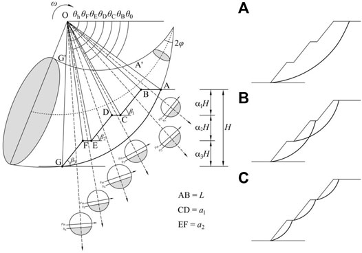
FIGURE 1. Collapse mechanism of the multi-stage slope: (A) overall failure; (B) local failure of two stage; (C) local failure of single stage.
and
where
The radius of the radial cross-section,
where the dimensionless expressions,
Unlike single-stage slopes, the collapse mechanisms of multi-stage slopes include overall failure and local failure. Figure 1A shows the slip surface of overall failure in the symmetry plane. Figure 1B shows the two-stages slip surface of local failure, and Figure 1C shows the single-stage slip surface of local failure in the symmetry plane.
By splitting the 3D collapse mechanism through the symmetry plane and inserting a plane-strain failure block with the width

FIGURE 2. Schematic diagram of the composite collapse mechanism for the multi-stage slope.
In addition, some significant derivations of geometrical relations which has shown in Figure 1 are provided in Supplementary Appendix SA. The variables in Figure 1 corresponds to the same derivations in Supplementary Appendix SA
The upper bound of LAM requires establishing the work rate balance equation. Soil weights of the failure block and seismic actions contribute to the external work rates, namely
The work rate
where
The work rates
where
The modified PDM considers the spatiotemporal effects of seismic waves, indicating that the seismic acceleration
The internal energy dissipation
where
Stability Analysis Process of Multi-Stage Slopes
Safety Factor
The strength reduction technique is introduced to the upper bound of LAM to obtain the safety factor of multistage slopes, which is defined as follows:
where
It should be noted that the obtained calculations of safety factors are the upper bounds to the actual solutions. An optimization procedure is established to find out the minimum safety factor among all possible calculations. The best estimation of safety factors could be obtained by varying the variables:
Analytical Process of the Multi-Stage Slope
For most multi-stage slopes, it is much more possible to occur overall failure. However, for the multi-stage slopes with some special cases, the collapse mechanism not only includes overall failure but also local failure. If the mechanism of these types of slopes is assumed to be overall failure, it may result in incorrect estimation of slope stability.
The present study proposed a new analytical process for the stability assessment of multi-stage slopes. Firstly, it is required to define a critical safety factor
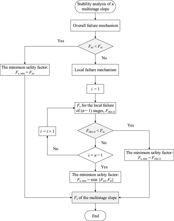
FIGURE 3. Flow diagram of the stability analysis for multi-stage slopes.
Results and discussion
Comparison
To verify the proposed approach for multi-stage slopes, three steps are carried out here to provide cogent comparisons. First, multi-stage slopes can be degraded into single-stage slopes in the case of
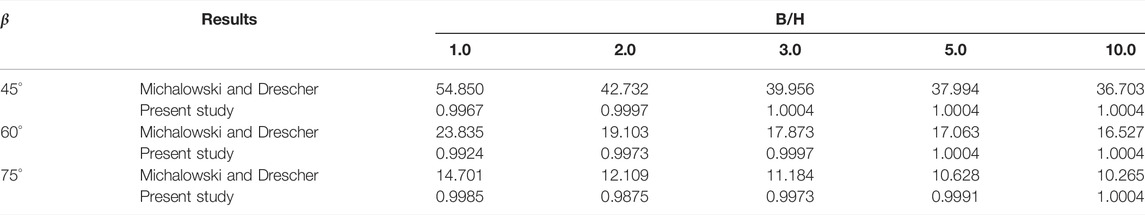
TABLE 1. Comparison of the results with Michalowski and Drescher (2009) for
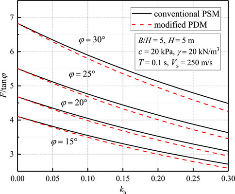
FIGURE 4. Comparison of the results obtained by the PSM and the modified PDM. Corresponding parameters:
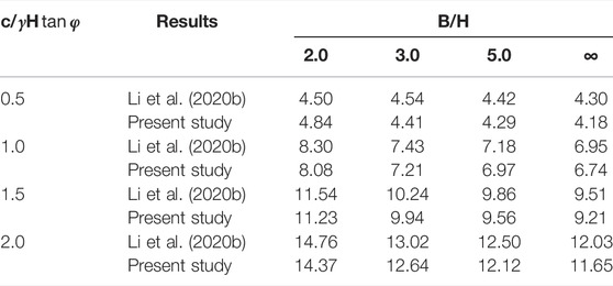
TABLE 2. Comparison of the results with Li et al. (2020b) for
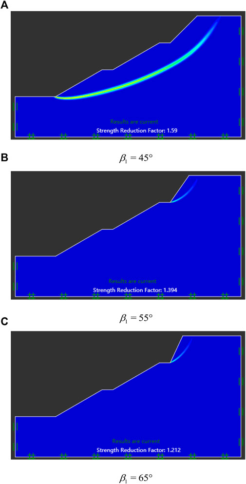
FIGURE 5. Results of multi-stage slopes obtained by the FEM for LA. Corresponding parameters:
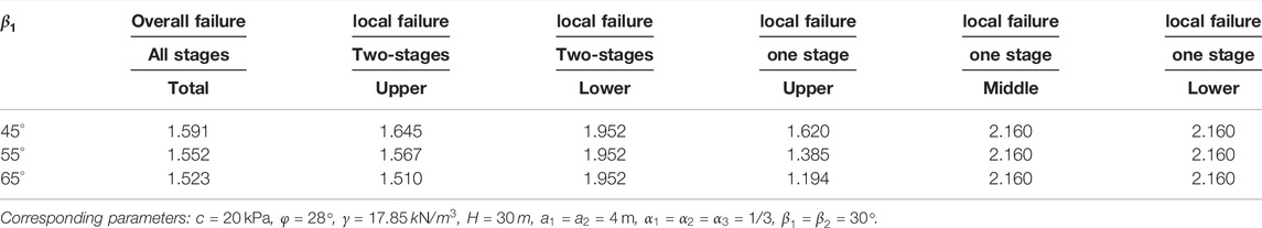
TABLE 3. Safety factors of all collapse mechanisms for multi-stage slopes.
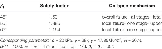
TABLE 4. Safety factors and collapse mechanisms of multi-stage slopes obtained by the present study.
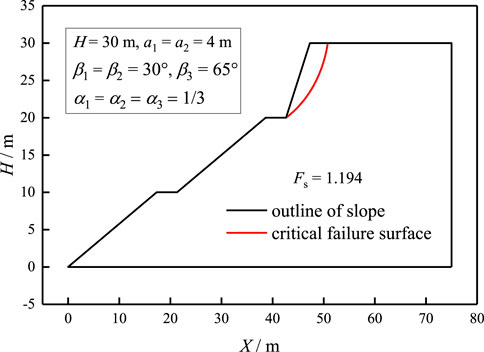
FIGURE 6. Slip surface obtained by the present study. Corresponding parameters are the same as those in Figure 5C.
Illustrative Example
In this section, the effects of different factors on the collapse mechanism for multi-stage slopes will be discussed by several illustrative examples. Firstly, the effect of seismic action is investigated, as shown in Table 5. We can conclude that safety factors of multi-stage slopes are getting smaller with the increase of
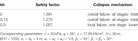
TABLE 5. Safety factors and collapse mechanisms of multi-stage slopes under different seismic coefficients
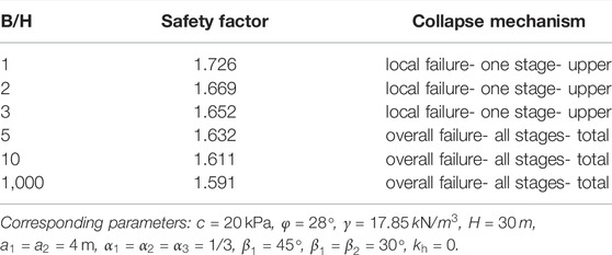
TABLE 6. Safety factors and collapse mechanisms of multi-stage slopes under different ratios of
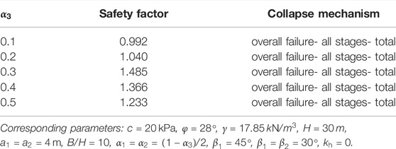
TABLE 7. Safety factors and collapse mechanisms of multi-stage slopes under different ratios of
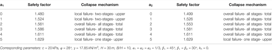
TABLE 8. Safety factors and collapse mechanisms of multi-stage slopes under different widths of
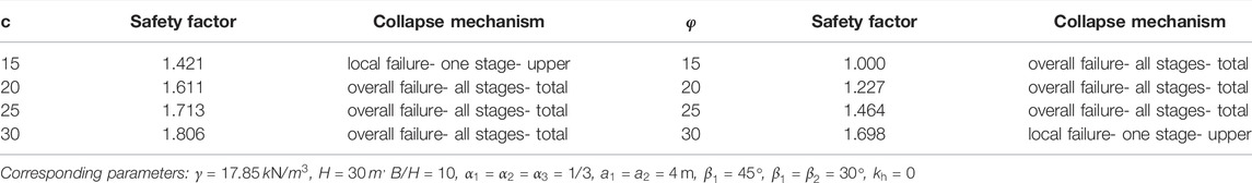
TABLE 9. Safety factors and collapse mechanisms of multi-stage slopes under different soil parameters.
In summary, we can conclude that seismic effects, ratios of
Parametric Analysis
This section is dedicated to analyzing the effects of seismic effects, soil parameters, and slope shapes on the stability of multi-stage slopes for a wide range of parameters. In the following discussion, soil parameters are assigned as:
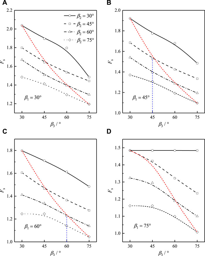
FIGURE 7. Safety factors of multi-stage slopes with different slop angles: (A)
As illustrated in Figure 8, slope stability increases as the step width (
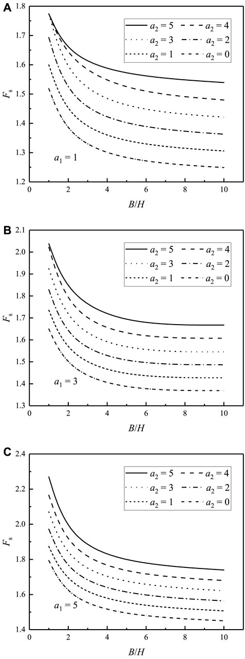
FIGURE 8. Safety factors of multi-stage slopes with different step widths: (A)
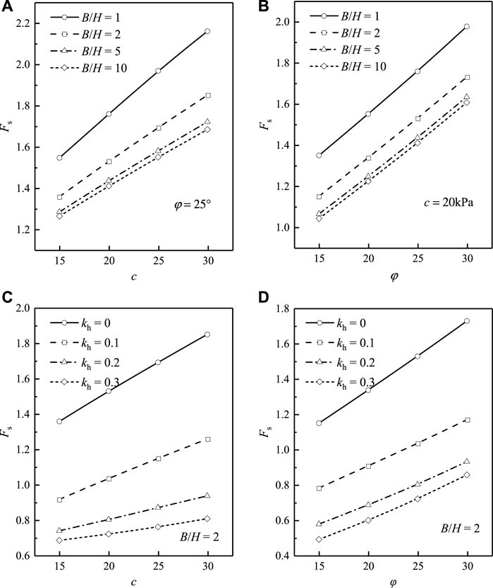
FIGURE 9. Safety factors of multi-stage slopes with different soil parameters: (A)
Figure 10 shows the variation of safety factors for different seismic parameters. It can be observed that the increase of acceleration coefficient
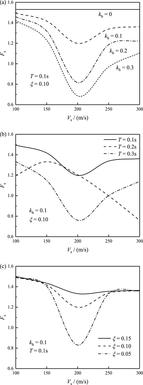
FIGURE 10. Safety factors of multi-stage slopes with different shear wave velocities: (A)
Submitting
Combining Eq 24, 11, the ratio of the acceleration amplitude at the surface can be obtained, as shown in Figure 11. From Figure 11, we can find that the seismic acceleration amplitude is magnified as the frequency of seismic waves being close to the natural frequencies of soils. Moreover, a large damping ratio would decline the seismic acceleration amplitude. Thus, the vibration of seismic acceleration results in the variability trends of safety factors in Figure 10.
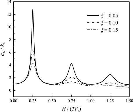
FIGURE 11. Ratios of the acceleration amplitude at the surface to the base.
Conclusion
The 3D collapse mechanism for single-stage slopes is extended to consider local failure for multi-stage slopes. The modified PDM is introduced to properly depict the seismic effect. The influence of slope shapes, soil parameters, and seismic effects on the collapse mechanism as well as safety factors are investigated by some illustrative examples and parametric analyses. The following conclusions can be obtained:
1) For a multi-stage slope, the seismic effect, ratios of
2) The multi-stage slope with a smaller slope angle in the lower stage and a larger slope angle in the upper stage is more possibly subject to local failure. Large step width is of benefit to slope stability, whereas a small ratio of
3) The modified pseudo-dynamic method could account for seismic effects concerning time and space. The seismic acceleration amplitude would be significantly magnified as the natural frequency of soils draw near to that of seismic waves. The damping effects of soils can reduce the adverse impacts of seismic actions. Specifically, the increase of acceleration coefficient and damping ratio would reduce the slope stability. The PDE depicts a nonlinear trend of seismic acceleration with the variation of wave velocity and vibration period, resulting in the synchronize nonlinear changes of safety factors.
Data Availability Statement
The original contributions presented in the study are included in the article/Supplementary Material, further inquiries can be directed to the corresponding author.
Author Contributions
Writing and Analysis: HW; Supervision: MS; Review and Editing: JW.
Conflict of Interest
HW was employed by the company Zhejiang Provincial Seaport Investment & Operation Group Co., Ltd, and MS was employed by the company PowerChina Huadong Engineering Corporation Limited.
The remaining author declares that the research was conducted in the absence of any commercial or financial relationships that could be construed as a potential conflict of interest.
Publisher’s Note
All claims expressed in this article are solely those of the authors and do not necessarily represent those of their affiliated organizations, or those of the publisher, the editors and the reviewers. Any product that may be evaluated in this article, or claim that may be made by its manufacturer, is not guaranteed or endorsed by the publisher.
Supplementary Material
The Supplementary Material for this article can be found online at: https://www.frontiersin.org/articles/10.3389/feart.2022.798791/full#supplementary-material
References
Baker, R., Shukha, R., Operstein, V., and Frydman, S. (2006). Stability Charts for Pseudo-static Slope Stability Analysis. Soil Dyn. Earthq. Eng. 26 (9), 813–823. doi:10.1016/j.soildyn.2006.01.023
Bellezza, I. (2015). Seismic Active Earth Pressure on Walls Using a New Pseudo-dynamic Approach. Geotech. Geol. Eng. 33 (4), 795–812. doi:10.1007/s10706-015-9860-1
Bıshop, A. W. (1954). The Use of the Slip Circle in the Stability Analysis of Earth Slopes. Geotechnique 5, 7–17.
Chen, G.-H., Zou, J.-F., Pan, Q.-J., Qian, Z.-H., and Shi, H.-Y. (2020). Earthquake-induced Slope Displacements in Heterogeneous Soils with Tensile Strength Cut-Off. Comput. Geotechnics 124, 103637. doi:10.1016/j.compgeo.2020.103637
Choudhury, D., and Katdare, A. D. (2013). New Approach to Determine Seismic Passive Resistance on Retaining Walls Considering Seismic Waves. Int. J. Geomech. 13 (6), 852–860. doi:10.1061/(asce)gm.1943-5622.0000285
Choudhury, D., and Nimbalkar, S. S. (2006). Pseudo-dynamic Approach of Seismic Active Earth Pressure behind Retaining Wall. Geotech. Geol. Eng. 24 (5), 1103–1113. doi:10.1007/s10706-005-1134-x
Gao, Y.-f., Ye, M., and Zhang, F. (2015). Three-dimensional Analysis of Slopes Reinforced with Piles. J. Cent. South Univ. 22 (6), 2322–2327. doi:10.1007/s11771-015-2757-6
Ghosh, P. (2008). Seismic Active Earth Pressure behind a Nonvertical Retaining Wall Using Pseudo-dynamic Analysis. Can. Geotech. J. 45 (1), 117–123. doi:10.1139/t07-071
Griffiths, D. V., and Marquez, R. M. (2007). Three-dimensional Slope Stability Analysis by Elasto-Plastic Finite Elements. Géotechnique 57 (6), 537–546. doi:10.1680/geot.2007.57.6.537
He, Y., Liu, Y., Zhang, Y., and Yuan, R. (2019). Stability Assessment of Three-Dimensional Slopes with Cracks. Eng. Geol. 252, 136–144. doi:10.1016/j.enggeo.2019.03.001
Li, T. Z., and Yang, X. L. (2020a). Stability of Plane Strain Tunnel Headings in Soils with Tensile Strength Cut-Off. Tunn. Undergr. Space Technol. 95, 103138. doi:10.1016/j.tust.2019.103138
Li, Z.-W., Yang, X.-L., and Li, T.-Z. (2020b). Static and Seismic Stability Assessment of 3D Slopes with Cracks. Eng. Geol. 265, 105450. doi:10.1016/j.enggeo.2019.105450
Michalowski, R. L., and Drescher, A. (2009). Three-dimensional Stability of Slopes and Excavations. Géotechnique 59 (10), 839–850. doi:10.1680/geot.8.p.136
Michalowski, R. L. (2013). Stability Assessment of Slopes with Cracks Using Limit Analysis. Can. Geotech. J. 50 (10), 1011–1021. doi:10.1139/cgj-2012-0448
Morgenstern, N. R., and Price, V. E. (1965). The Analysis of the Stability of General Slip Surfaces. Géotechnique 15 (1), 79–93. doi:10.1680/geot.1965.15.1.79
Nadukuru, S. S., and Michalowski, R. L. (2013). Three-dimensional Displacement Analysis of Slopes Subjected to Seismic Loads. Can. Geotech. J. 50 (6), 650–661. doi:10.1139/cgj-2012-0223
Pain, A., Choudhury, D., and Bhattacharyya, S. K. (2017). Seismic Rotational Stability of Gravity Retaining Walls by Modified Pseudo-dynamic Method. Soil Dyn. Earthq. Eng. 94, 244–253. doi:10.1016/j.soildyn.2017.01.016
Pan, Q., Jiang, Y.-J., and Dias, D. (2017). Probabilistic Stability Analysis of a Three-Dimensional Rock Slope Characterized by the Hoek-Brown Failure Criterion. J. Comput. Civ. Eng. 31 (5), 04017046. doi:10.1061/(asce)cp.1943-5487.0000692
Qin, C.-B., and Chian, S. C. (2018). Kinematic Analysis of Seismic Slope Stability with a Discretisation Technique and Pseudo-dynamic Approach: a New Perspective. Géotechnique 68 (6), 492–503. doi:10.1680/jgeot.16.p.200
Qin, C., and Chian, S. C. (2020). Pseudo-dynamic Lateral Earth Pressures on Rigid Walls with Varying Cohesive-Frictional Backfill. Comput. Geotechnics 119, 103289. doi:10.1016/j.compgeo.2019.103289
Qin, C., and Chian, S. C. (2019). Pseudo-static/dynamic Solutions of Required Reinforcement Force for Steep Slopes Using Discretization-Based Kinematic Analysis. J. Rock Mech. Geotechnical Eng. 11 (2), 289–299. doi:10.1016/j.jrmge.2018.10.002
Shen, J., and Karakus, M. (2014). Three-dimensional Numerical Analysis for Rock Slope Stability Using Shear Strength Reduction Method. Can. Geotech. J. 51 (2), 164–172. doi:10.1139/cgj-2013-0191
Steedman, R. S., and Zeng, X. (1990). The Influence of Phase on the Calculation of Pseudo-static Earth Pressure on a Retaining Wall. Géotechnique 40 (1), 103–112. doi:10.1680/geot.1990.40.1.103
Terzaghi, K. (1950). Mechanism of Landslides. Application of Geology to Engineering Practice. Geological Society of America, 83.
Wang, H., Zhang, B., Mei, G., and Xu, N. (2020a). A Statistics-Based Discrete Element Modeling Method Coupled with the Strength Reduction Method for the Stability Analysis of Jointed Rock Slopes. Eng. Geol. 264, 105247. doi:10.1016/j.enggeo.2019.105247
Wang, L., Hu, W., Sun, D. A., and Li, L. (2019a). 3D Stability of Unsaturated Soil Slopes with Tension Cracks under Steady Infiltrations. Int. J. Numer. Anal. Methods Geomech. 43 (6), 1184–1206. doi:10.1002/nag.2889
Wang, L., Sun, D. A., and Li, L. (2019b). Three-dimensional Stability of Compound Slope Using Limit Analysis Method. Can. Geotech. J. 56 (1), 116–125. doi:10.1139/cgj-2017-0345
Wang, M.-Y., Liu, Y., Ding, Y.-N., and Yi, B.-L. (2020b). Probabilistic Stability Analyses of Multi-Stage Soil Slopes by Bivariate Random Fields and Finite Element Methods. Comput. Geotechnics 122, 103529. doi:10.1016/j.compgeo.2020.103529
Yang, X. L., and Li, Z. W. (2018). Factor of Safety of Three-Dimensional Stepped Slopes. Int. J. Geomech. 18 (6), 04018036. doi:10.1061/(asce)gm.1943-5622.0001154
Yang, X. L., and Long, Z. X. (2015). Seismic and Static 3D Stability of Two-Stage Rock Slope Based on Hoek–Brown Failure Criterion. Can. Geotechnical J. 53 (3), 551–558.
Zhang, Z.-L., and Yang, X.-L. (2021). Seismic Stability Analysis of Slopes with Cracks in Unsaturated Soils Using Pseudo-dynamic Approach. Transp. Geotech. 29, 100583. doi:10.1016/j.trgeo.2021.100583
Zhong, J. H., and Yang, X. L. (2021). Pseudo-dynamic Stability of Rock Slope Considering Hoek–Brown Strength Criterion. Acta Geotech., 1–14.
Keywords: multi-stage slope, overall failure, local failure, seismic effect, modified pseudo-dynamic approach
Citation: Wu H, Sun M and Wang J (2022) Stability Assessment of Multi-Stage Slopes Considering Local Failure. Front. Earth Sci. 10:798791. doi: 10.3389/feart.2022.798791
Received: 20 October 2021; Accepted: 26 April 2022;
Published: 20 June 2022.
Edited by:
Yun JIA, University in Lille, FranceReviewed by:
Zhibin Sun, Hefei University of Technology, ChinaNipa Chanda, CMR Institute of Technology (CMR IT), India
Copyright © 2022 Wu, Sun and Wang. This is an open-access article distributed under the terms of the Creative Commons Attribution License (CC BY). The use, distribution or reproduction in other forums is permitted, provided the original author(s) and the copyright owner(s) are credited and that the original publication in this journal is cited, in accordance with accepted academic practice. No use, distribution or reproduction is permitted which does not comply with these terms.
*Correspondence: Miaojun Sun, c3VubWo4MTZAaG90bWFpbC5jb20=