 Yaodong Li1
 Yang Sun
95% of researchers rate our articles as excellent or good
Learn more about the work of our research integrity team to safeguard the quality of each article we publish.
Find out more
BRIEF RESEARCH REPORT article
Front. Earth Sci. , 08 March 2022
Sec. Structural Geology and Tectonics
Volume 10 - 2022 | https://doi.org/10.3389/feart.2022.794756
This article is part of the Research Topic Applications of Geotechnical Mechanics in Underground Engineering View all 41 articles
The number of special-shaped foundation pits is increasing fast because of the continuous utilization of underground spaces in urban areas. Based on the deep foundation pit of Maluan North Station of Xiamen Metro Line 2 in Xiamen, China, the deformation characteristics of the supporting structure of special-shaped foundation pits are researched by field observation and numerical simulation. Meanwhile, the depth of the concrete supports and steel supports is considered, respectively. The results show that the lateral deformation of the diaphragm wall at the corner of the pit shows obvious corner effect, and the maximum lateral displacement of the long-side diaphragm wall is slightly larger than the short-side diaphragm wall. Changing the position of the second layer of steel support has almost no effect on the lateral deformation of the corner diaphragm wall. Changing the position of the second layer of concrete support has a greater impact on the lateral displacement of the diaphragm wall, but the path of the maximum lateral displacement of the diaphragm wall and the depth of the point of maximum lateral displacement remain unchanged.
With the development of economy and the acceleration of urbanization, urban traffic congestion has become an increasingly serious problem. More and more engineering constructions are turning to underground space such as subways, highway tunnels, underground parking lots, and underground shopping malls. The foundation pits of most subway stations are generally deep and long with different shapes. In order to reduce the impact on the surrounding environment, diaphragm walls and internal support systems are used for the enclosure structure. Furthermore, it is rather necessary to carry out long-term tracking monitoring to ensure the safety and stability of the foundation pit, but the number of monitoring points is limited, and numerical simulation methods are usually used to supplement the on-site monitoring.
As early as the 1990s, the existence of the pit corner effect was verified by scholars; then, the corner effect of foundation pit excavation was studied through site monitoring and finite element methods (FEM) (Ou et al., 1996; Lee et al., 1998). Ou et al. (2000) studied the three-dimensional movement of soil and walls through field monitoring and finite element analysis and found that the settlement of the soil at the corner of the pit was less than the settlement of the soil at the center. Taking a certain foundation pit in London as an example, Zdravkovic et al. (2005) compared three-dimensional finite element calculation with two-dimensional plane strain analysis (rectangular foundation pit), and pointed out that the use of plane strain analysis for rectangular foundation pits cannot account for the spatial distribution of its deformation, and the calculation results have large errors. According to the study of Finno et al. (2007), the influence range of the pit corner effect is approximately 3 times the depth of the excavation of the foundation pit. When the side length of the foundation pit is greater than 6 times the excavation depth, the soil displacement in the middle of the foundation pit between the results of the plane strain simulation and the results of the three-dimensional simulation is the same, indicating that the influence of the pit corner effect can be ignored at this time. Zheng and Li (2012) studied the influence of the pit corner effect on the surrounding buildings of the foundation pit and found that the buildings near the corner of the foundation pit were twisted and deformed due to the uneven settlement of the soil outside the pit, which seriously endangered the building. Jia et al. (2016) found through indoor model test and FLAC3D numerical simulation that the influence range of the earth pressure corner effect in the horizontal direction is within 0.2 times the excavation depth from the corner. Hsiung et al. (2016); Hsiung et al. (2018), carrying out parameter inversion and model verification based on the foundation pit monitoring data and field and indoor geotechnical test data, discussed the influence of different sizes of foundation pits on the pit angle effect and drew a PSR experience chart. Fan (2016) studied the influence of the support structure on the deformation of the deep foundation pit and obtained the functional relationship between the deformation of the inner and outer corner walls and the distance of the foundation pit corner. Zheng and Zheng (2017) deduced the calculation formula of earth pressure under the corner effect. Chheng and Likitlersuang (2017) found that the two-dimensional model cannot consider the effect of the corner, which will cause the lateral displacement of the diaphragm wall calculated by the corner to be too large. Liang (2018) used PLAXIS 3D finite element software calculations and site monitoring data to analyze the changes and distribution of earth pressure on the diaphragm wall during the excavation process. Wang (2019) extended the concept of PSR, using the lateral displacement of the diaphragm wall (PSRh) and the ground surface settlement (PSRv) to quantify the corner effect, and established a multivariate adaptive regression spline (MARS) model for estimating PSR. Liu et al. (2017) analyzed the spatial effect of the deformation of the special-shaped foundation pit–supporting structure, and the results showed that the deformation of the supporting structure at different plane positions also showed obvious spatial effects. The position of the inner corner has a strong ability to constrain the deformation, and the main influence range of the pit angle effect is within a distance of about 1 time the excavation depth from the pit corner. When the distance from the pit angle exceeds 3 times the excavation depth, it enters the long-side effect influence range. Tan et al. (2020) analyzed the law of lateral deformation of the diaphragm wall of the special-shaped foundation pit based on the project of Maluan North Station (MNS). Bai (2020) studied the influence of special-shaped foundation pit construction on adjacent buildings, in which the deformation of adjacent buildings with right-angle pit corners is smaller than that of adjacent buildings with pit angles greater than 90°.
So far, the research on the pit corner effect is mainly based on the rectangular foundation pit, and the research on the corner effect of special-shaped foundation pits is less. Therefore, in this study, the deformation characteristics of the diaphragm wall of the special-shaped foundation pit are investigated based on the MNS project of Xiamen Metro Line 2 in Xiamen, China. On that basis, the effect of two main facts, including the depth of concrete supports and steel supports near the corner, on the deformation characteristics of special-shaped foundation pits is studied by the ABAQUS finite element. The conclusions of the corner effect in the process of pit excavation can be provided as a reference for actual engineering support schemes.
MNS foundation pit is in Haicang district in Xiamen, China. The plane shape of MNS foundation pit is irregular. The maximum excavation length and width are about 348 and 20.7 m, respectively. The excavation depth of the standard section is 10.7 m, and the depth of the special-shaped section is about 14 m. The 600-mm-thick diaphragm walls and internal supports are used as the main supporting structures of the foundation pit, and the concrete strength of the diaphragm wall is C35. The first supports of the standard section are 800 mm × 1000 mm concrete supports, which are supported on the crown beams, and the second supports are steel supports with a diameter of 800 mm and a thickness of 16 mm; two concrete gussets are set at the corners of the foundation pit.
There are no important structures within the scope of the foundation pit project of MNS. Mainly fish ponds for local villagers and Guoyun Creek are located near the project site. The area is located at the junction of urban and rural areas in Haicang district, Xiamen. Mainly for living and green space, it is now the planning area of Maluan New Town in Xiamen, with good construction conditions. There are also no pipelines in the surrounding area.
Table 1 shows the soil parameters. The stratum structure along the foundation pit project is complex, the rock and soil layers are unevenly distributed, and the engineering geological conditions are poor. Plain fill soil has poor engineering characteristics, which is not conducive to slope stability of foundation pits. The soft soil is marine silt, which is in the form of flowing plastic to soft plastic, with unfavorable engineering characteristics. Sand-mixed silt is dominated by sub-circular quartz medium and coarse sand, with a mud content of about 30%, and uneven particle size. Tuff lava residual cohesive soil and full or strong weathered rock have poor uniformity and different strengths. They are easy to soften when brought in contact with water and have sharply reduced strength. The engineering performance of rock and soil is generally poor.
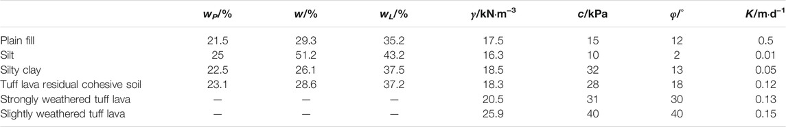
TABLE 1. Soil parameters.
The ABAQUS finite element software was used to establish a three-dimensional finite element model of MNS foundation pit and simulate the whole process of foundation pit excavation. The soil adopts the Mohr–Coulomb model. The diaphragm walls, concrete supports, and steel supports are all assumed to be elastic materials, and their density (ρ), elastic modulus (E), and Poisson ratio (υ) are shown in Table 2.
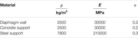
TABLE 2. Material parameters of foundation pit supporting structure.
In order to avoid the influence of the model boundary, the model size is 3 times the size of the pit. The size of the calculated model is 120 m × 56 m×60 m. The models all use C3D8R solid elements, and a total of 59474 grids are generated. The calculation boundary conditions are as follows: the displacement of the side in the Y direction is free, the bottom surface is completely fixed, and the top surface is free.
In the ABAQUS numerical simulation, the construction of diaphragm walls, erection of supports, and excavation of soil are controlled by the dead–live unit method. Numerical simulation steps of foundation pit excavation are given as follows:
Step 1: Calculate the model soil for initial ground stress balance.
Step 2: A uniform load of 10 kPa is added within 10 m around the foundation pit.
Step 3: Excavate the first layer of soil to 1 m below the surface, and construct the first concrete support.
Step 4: Excavate the second layer of soil to 4 m below the surface.
Step 5: Excavate the third layer of soil to 6 m below the surface, and construct the second steel support.
Step 6: Excavate the fourth layer of soil to 8 m below the surface.
Step 7: Excavate the fifth layer of soil to 11 m below the surface.
Step 8: Excavate the sixth layer of soil to 14 m below the surface.
As can be seen from Figure 1, AB, BC, and DE are defined as diaphragm wall 1, diaphragm wall 2, and diaphragm wall 3, respectively.

FIGURE 1. Paths and measuring points of diaphragm walls.
Figure 2A shows the lateral wall displacements at ZQT33, ZQT34, ZQT35, and ZQT37 when the excavation of the foundation pit is completed. The displacement to the outside of the pit is specified as negative; otherwise, it is positive. The deformation curves of diaphragm walls show a small up and down, and a large change in the middle, which are consistent with Han (2020)’s research. There is no horizontal support at the bottom of the diaphragm walls, but its lateral displacement is small. The reason is that the bottom soil is tough with high strength, and the diaphragm walls are embedded in the rock and soil to obtain a large embedding force. However, the soil in the middle section of the foundation pit is mainly silty soil, and it is easy to generate a large earth pressure during the excavation of the slope of the foundation pit, resulting in a large deformation of the diaphragm wall. The measuring points ZQT33 and ZQT34 are distributed on diaphragm wall 3. Their deformation laws are the most similar, and the maximum lateral displacement values are not much different. The lateral displacement values of the measuring points ZQT35 and ZQT37 are quite different. ZQT37 is located at the end of diaphragm wall 1, which has the smallest lateral displacement.
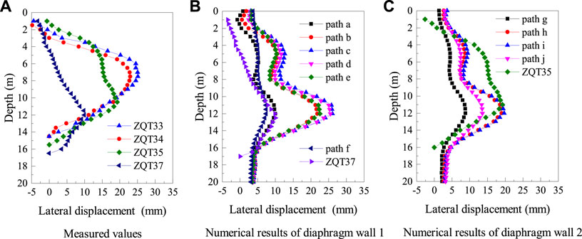
FIGURE 2. Comparison of measured values and numerical results of lateral displacement. (A) Measured values; (B) numerical results of diaphragm wall 1; (C) numerical results of diaphragm wall 2.
The support arrangement of program 1 is as follows: taking the ground surface of the foundation pit as an elevation of 0.0 m, the elevations of the bottom of the two concrete supports at the corner of the pit are −1.0 m and −8.0m, respectively, and the central elevations of the concrete supports and the steel supports of the standard section are −1.0 m and −8.5 m, respectively. The numerical results of the lateral displacement of diaphragm wall 1 and diaphragm wall 2 are shown in Figure 2B; Figure 2C, respectively. As can be seen, path f has the smallest lateral displacement, which is closest to corner B. Path c of diaphragm wall 1 is far away from corners A and B, and the maximum lateral displacement reaches 26 mm. Paths h and i of diaphragm wall 2 are far away from corners B and C, and the curves basically coincide with a maximum value of 19 mm. Paths g and j are close to corners B and C, respectively, but the lateral displacement values of the two are quite different. Although corners B and C are both right angles, the former is formed by two long diaphragm walls and the latter is formed by a long wall and a short wall. The different support structures at the corners have different effects on the lateral wall displacements.
The support arrangement of program 2 is as follows: taking the ground surface of the foundation pit as an elevation of 0.0 m, the elevations of the bottom of the two concrete supports at the corner of the pit are −1.0 m and −8.0 m, respectively, and the central elevations of the concrete supports and the steel supports of the standard section are −1.0 m and −7.5 m, respectively. Figure 3A and Figure 3B show the lateral displacements of each path of diaphragm wall 1 and diaphragm wall 2, respectively. According to the lateral displacement diagrams of diaphragm walls 1 and 2 in program 1, the lateral displacements of paths c and d are rather larger. Therefore, changing the support position, the lateral displacements of paths c and d of program 2 and the lateral displacement of path c of program 1 are selected for comparative analysis. Both figures reflect that changing the position of the second layer of steel supports has almost no effect on the lateral wall deformation at the corner of the pit. The lateral displacements of path c of diaphragm wall 1 and path i of diaphragm wall 2 are still the largest, and the maximum lateral displacement value has only a small change. This may be due to the fact that the second steel support is set at the standard section of the foundation pit, that is, on diaphragm wall 3, and has little effect on the diaphragm wall near corner B.
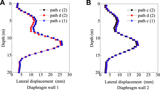
FIGURE 3. Numerical results of lateral displacement of diaphragm walls 1 and 2 in program 2. (A) Diaphragm wall 1; (B) diaphragm wall 2
The support arrangement of program 3 is as follows: taking the ground surface of the foundation pit as an elevation of 0.0 m, the elevations of the bottom of the two concrete supports at the corner of the pit are −1.0 m and −9.0 m, respectively, and the central elevations of the concrete supports and the steel supports of the standard section are −1.0 m and −8.5 m, respectively. Figure 4A and Figure 4B show the numerical results of the lateral displacement of each path of diaphragm walls 1 and 2 after the foundation pit is excavated, respectively. As can be seen, changing the position of the second layer of concrete supports has a greater impact on the lateral deformation of diaphragm walls 1 and 2. As far as path c of diaphragm wall 1 is concerned, the maximum lateral displacement in program 2 is only 23.92 mm, which is 2.15 mm smaller than that in program 1. Similarly, in terms of path i, the lateral displacement of program 1 is 1.56 mm smaller than that of program 2. Although the maximum lateral displacement of the diaphragm wall is much smaller than that in program 1, the lateral displacement at a depth of 5 m is more than that in program 1. Since the second layer of concrete supports was set 9 m below the surface, the maximum lateral displacement point of the upper half of the diaphragm wall also moved downward, with a depth of about 6 m. On the whole, the path of the maximum lateral displacement of the diaphragm wall and the depth of the point of maximum lateral displacement have not changed, but the value of the maximum lateral displacement has been reduced. There are many factors affecting the deformation of the diaphragm wall, including the thickness of diaphragm walls, soil parameters, and the position of the horizontal support. This study only discusses the influence of the position of the horizontal support. The research shows that the second horizontal support acting at the corner of the pit has a significant impact on the deformation of the diaphragm wall. By seeking its optimal position, the lateral displacement of the diaphragm wall can be effectively decreased, the safety of the foundation pit structure can be ensured, and the engineering cost can be minimized.
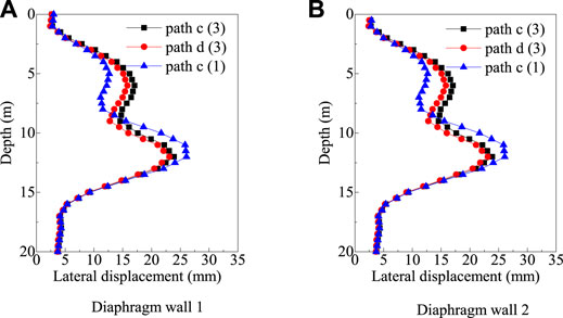
FIGURE 4. Numerical results of lateral displacement of diaphragm walls 1 and 2 in program 3. (A) Diaphragm wall 1; (B) diaphragm wall 2
(1) During the excavation of the foundation pit, the existence of the pit corner has a constraining effect on the deformation of the diaphragm wall. As far as the lateral displacement of the diaphragm wall is concerned, the value near the pit corner is smaller than the value far away from the pit corner.
(2) In a special-shaped foundation pit, the lengths of the diaphragm walls are different, and the support structure at the corners of the pit is also different. The corner effect caused by the corner, which was formed by two long diaphragm walls, is more obvious than that caused by the other corner, which was formed by two short diaphragm walls, that is, when two paths distance and different corners are same, the displacement of the former is smaller.
(3) The horizontal support structure at the pit corner has an influence on the lateral displacement of the diaphragm wall near the corner, and the horizontal support located in the middle has a significant effect on the maximum lateral displacement of the diaphragm wall.
The data analyzed in this study is subject to the following licenses/restrictions: The original contributions presented in the study are included in the article/supplementary material; further inquiries can be directed to the corresponding author. Requests to access these datasets should be directed to c3VueWFuZ19oaHVAaGh1LmVkdS5jbg==.
YS, GS, and RW were responsible for the project design, YL carried out field monitoring and numerical modeling, and CW and YJ conducted statistical analysis of the data.
This work was supported by the National Natural Science Foundation of China (grant number 41672257) and the Science and Technology Project of Zhejiang Provincial Transportation Department (grant number 2020014).
Author JY is employed by Hangzhou Jinghang Canal Second Channel Construction Investment Co., Ltd.
The remaining authors declare that the research was conducted in the absence of any commercial or financial relationships that could be construed as a potential conflict of interest.
All claims expressed in this article are solely those of the authors and do not necessarily represent those of their affiliated organizations, or those of the publisher, the editors, and the reviewers. Any product that may be evaluated in this article, or claim that may be made by its manufacturer, is not guaranteed or endorsed by the publisher.
Bai, W. F. (2020). “The Influence of Large Shaped by Deep Excavation on Adjacent High-Buildings,” (Shanxi, China: Xi’an Technological University). MSc Thesis.
Chheng, C., and Likitlersuang, S. (2017). Underground Excavation Behaviour in Bangkok Using Three-Dimensionalfinite Element Method. Comput. Geotechnics 95, 68–81. doi:10.1016/j.compgeo.2017.09.016
Fan, D. L. (2016). “Research on the Influence of Deep Foundation Pit Excavation on the Deformation of the Enclosure Structure Based on the Pit Angle Effect,” (Sichuan, China: Southwest Petroleum University). MSc Thesis.
Finno, R. J., Blackburn, J. T., and Roboski, J. F. (2007). Three-Dimensional Effects for Supported Excavations in Clay. J. Geotech. Geoenviron. Eng. 133 (1), 30–36. doi:10.1061/(asce)1090-0241(2007)133:1(30)
Han, P. C. (2020). “Study on Deformation Law and Corner Effect of Irregular Deep Foundation Pit in Subway Station,” (Hebei, China: Shijiazhuang Tiedao University). MSc Thesis.
Hsiung, B.-C. B., Yang, K.-H., Aila, W., and Ge, L. (2018). Evaluation of the wall Deflections of a Deep Excavation in Central Jakarta Using Three-Dimensional Modeling. Tunnelling Underground Space Techn. 72 (72), 84–96. doi:10.1016/j.tust.2017.11.013
Hsiung, B.-C. B., Yang, K.-H., Aila, W., and Hung, C. (2016). Three-dimensional Effects of a Deep Excavation on wall Deflections in Loose to Medium Dense Sands. Comput. Geotechnics 80 (80), 138–151. doi:10.1016/j.compgeo.2016.07.001
Jia, M. C., Yang, X. H., and Ye, Z. J. (2016). Corner Effect of Active Earth Pressure for Small-Sized Excavation. J. Harbin Inst. Techn. 48 (12), 95–102. doi:10.11918/j.issn.0367-6234.2016.12.013
Lee, F. H., Yong, K. Y., Quan, K. C. N., and Chee, K. T. (1998). Effect of Corners in Strutted Excavations: Field Monitoring and Case Histories. J. Geotech. Geoenvironmental Eng. 124 (4), 339–349.
Liang, W. P. (2018). “Numerical and Theoretical Study on Behaviors of Deep Shaft Excavation,” (Zhejiang, China: Zhejiang University). MSc Thesis.
Liu, Z. Q., Wang, S. J., Liu, M. Z., and Liu, H. R. (2017). Three-dimensional Numerical Analysis of Retaining Structure Deformation for Irregular Excavation. J. Agric. Univ. Hebei 40 (06), 114–118.
Ou, C.-Y., Chiou, D.-C., and Wu, T.-S. (1996). Three-dimensional Finite Element Analysis of Deep Excavations. J. Geotechnical Eng. 122 (5), 337–345. doi:10.1061/(asce)0733-9410(1996)122:5(337)
Ou, C.-Y., Shiau, B.-Y., and Wang, I.-W. (2000). Three-dimensional Deformation Behavior of the Taipei National Enterprise Center (TNEC) Excavation Case History. Can. Geotech. J. 37 (2), 438–448. doi:10.1139/t00-018
Tan, J. B., Zheng, X. Y., Sun, Y., Shao, G. J., and Chen, Y. B. (2020). Analysis of Pit Corner Effect of Special-Shaped Foundation Pit of Subway Station. IOP Conf. Ser. Earth Environ. Sci. 558 (3), 032. doi:10.1088/1755-1315/558/3/032032
Wang, W. (2019). “Study on Corner Effect of Excavations in Clays,” (Chongqing, China: Chongqing University). MSc Thesis.
Zdravkovic, L., Potts, D. M., and St John, H. D. (2005). Modelling of a 3D Excavation in Finite Element Analysis. Géotechnique 55 (7), 497–513. doi:10.1680/geot.2005.55.7.497
Zheng, C., and Zheng, Z. G. (2017). Analysis and Study on protection System of Deep Foundation Pit when Considering Pit Corner Effect. Energ. Environ. Prot. 39 (4), 212–217. doi:10.19389/j.cnki.1003-0506.2017.04.045
Keywords: special-shaped foundation pit, on-site monitoring, numerical simulation, corner effect, lateral displacement
Citation: Li Y, Wang C, Sun Y, Wang R, Shao G and Yu J (2022) Analysis of Corner Effect of Diaphragm Wall of Special-Shaped Foundation Pit in Complex Stratum. Front. Earth Sci. 10:794756. doi: 10.3389/feart.2022.794756
Received: 14 October 2021; Accepted: 04 February 2022;
Published: 08 March 2022.
Edited by:
Chaojun Jia, Central South University, ChinaReviewed by:
Aizat Mohd Taib, National University of Malaysia, MalaysiaCopyright © 2022 Li, Wang, Sun, Wang, Shao and Yu. This is an open-access article distributed under the terms of the Creative Commons Attribution License (CC BY). The use, distribution or reproduction in other forums is permitted, provided the original author(s) and the copyright owner(s) are credited and that the original publication in this journal is cited, in accordance with accepted academic practice. No use, distribution or reproduction is permitted which does not comply with these terms.
*Correspondence: Yang Sun, c3VueWFuZ19oaHVAaGh1LmVkdS5jbg==
Disclaimer: All claims expressed in this article are solely those of the authors and do not necessarily represent those of their affiliated organizations, or those of the publisher, the editors and the reviewers. Any product that may be evaluated in this article or claim that may be made by its manufacturer is not guaranteed or endorsed by the publisher.
Research integrity at Frontiers
Learn more about the work of our research integrity team to safeguard the quality of each article we publish.