 P. Y. Zhou
 J. B. Wang
 Z. P. Song
 Z. L. Cao
 Z. M. Pei
95% of researchers rate our articles as excellent or good
Learn more about the work of our research integrity team to safeguard the quality of each article we publish.
Find out more
ORIGINAL RESEARCH article
Front. Earth Sci. , 04 March 2022
Sec. Geohazards and Georisks
Volume 10 - 2022 | https://doi.org/10.3389/feart.2022.770888
This article is part of the Research Topic New Development of Underground Energy Storage Using Mine Space View all 28 articles
The transfer section between the cross passage and the main tunnel is the part that needs to be paid attention to during the underground excavation construction of the subway. Due to complex stress, the collapse of the horsehead gate and excessive surface settlement often occur. In order to determine the construction scheme of the transfer section between the cross passage and the main tunnel of Guanshui Road Station of Metro Line two in Guiyang, China, the numerical simulation method was used to analyze the “double-holes interval pillar method,” “sector expansion method,” and “gate climbing method,”, respectively. The mechanical response of the surrounding rock and supporting structure under each method was compared. The comparisons showed that the surface settlement, the displacement of the cave, and the plastic zone caused by the double-holes interval pillar method were the smallest, and the method can reduce the construction risk, shorten the construction period, and reduce the project cost. Therefore, it was recommended to use the double-holes interval pillar method to construct the transfer section. The comparison between the measured data and the numerical simulation results of the double-holes interval pillar method showed that the numerical simulation results were smaller than the measured data at each point, and the surface settlement and horizontal displacement in the tunnel both met the safety control standard.
With the increase of underground tunnel construction, underground caverns are often used for energy storage. To ensure the safety of energy storage, builders must first ensure the construction safety of underground caverns (Comodromos et al., 2014; Ramos et al., 2018; Fan et al., 2019; Kang et al., 2021). However, the construction of an underground tunnel is complex (Janda et al., 2018; Wang et al., 2020; Fan JY. et al., 2020; Lv et al., 2020; Li et al., 2021), especially at the junction of a variable section. In order to reduce the impact on ground traffic, the undercutting method is usually used in the construction of an urban Metro with dense buildings (Bobet, 2001; Khademian et al., 2017; Cao et al., 2018; Moosavi et al., 2018; Li et al., 2019; Wang et al., 2021b). The cross passage near the Metro station is used as the connection part between the shaft and the main tunnel, and this transfer section between the shaft and the main tunnel is the key section of Metro station construction. The construction method of this transfer section is complex, and the stress of the supporting structure changes frequently during the construction process, which causes a more complex deformation and stress distribution of the surrounding rock-supporting system than conventional tunnels (Jiang et al., 2016; Djelloul et al., 2018; Sommer et al., 2018; Fan S.-y. et al., 2020; Wang et al., 2021a; Dong et al., 2021). Therefore, the selection of an appropriate construction method is of great significance to ensure the construction safety of the transfer section and even the entire Metro station.
In order to ensure the construction safety of the transfer section, scholars from all over the world have studied its construction mechanical effects. Hsiao et al. (2004) adopted numerical simulation to carry out feedback analysis on the complex stress in the crossing area of seven tunnels. The results showed that a tunnel should be in a stable state due to the small tunnel impact area and loose rock mass area, and real-time monitoring should be maintained to measure the displacement of the tunnel during excavation. Li et al. (2016) studied the deformation, stress, and plastic zone response of the surrounding rock at a tunnel intersection and the influence range of the lining failure mode by using the numerical simulation method. The numerical results showed that the deformation in a section close to the tunnel intersection was larger than the deformation in distant sections. Gaspari et al. (2010) used the numerical simulation method to study the lining structure scheme of the Metro intersection and determined the optimization measures of the lining structure. Hsiao et al. (2009) studied the mechanical effect of the rock mass in the transfer section with numerical simulation. They established the criteria for evaluating the influence of intersection angle on tunnel behavior, and determined three types of support design schemes for different geological conditions. Lin et al. (2013) studied the stability of the long-span tailrace bifurcation tunnel with complex three-dimensional geometry by using a theoretical calculation, and determined a non-linear reinforcement analysis method that could be used for the reinforced concrete lining and rock bolt design. Song Z. et al. (2018) studied the stress and deformation in the transfer section between the shaft and cross passage with numerical simulation, and determined a scheme that could effectively control the surface settlement and deformation of the shaft. Liu and Wang (2010) used numerical simulation to simulate the actual project according to the mechanical characteristics and stability of the bifurcated tunnel. By comparing the results from four conditions, they put forward the safest and most reliable scheme. Li et al. (2015) studied the influence of soil stiffness, structural components, and other key deformation mechanisms on the integrity of the cross structure in the cross passage with numerical simulation, and found that the lintel could transfer the load above the cross structure to the adjacent lining. In addition, relevant scholars also carried out a lot of research on the stress changes of the surrounding rock-supporting system during the cross structure construction (Daraei and Zare, 2018; Galli et al., 2004; Song ZP. et al., 2018). The research on specific projects had important guiding significance for the construction deformation and safety control of the transfer part between the main tunnel and the cross passage. However, most scholars have only discussed those projects with little difference in the section size between the cross passage and the main tunnel, while the research on the construction of the transfer section between the cross passage and the main tunnel with a large difference in section size is relatively less.
This paper studied the mechanical response of the transfer section between the cross passage and the main tunnel in the construction of Guanshui Metro station on Guiyang Metro line 2 in China. In order to determine the construction scheme of the transfer section, the numerical simulation method was used to simulate the construction process through three methods, namely, the “double-holes interval pillar method,” “sector expansion method,” and “gate climbing method”. The stress and displacement of the surrounding rock-supporting system and the distribution of the plastic zone of the surrounding rock caused by the three methods were analyzed. By comparing the calculation results of the three methods, it is suggested that the double-holes interval pillar method should be adopted in the construction. The comparison between the numerical simulation results and the monitoring data showed that the numerical simulation results were in good agreement with the measured results. The double-holes interval pillar method could better control the deformation of the tunnel-supporting structure and surrounding rock. The results can provide a reference for the design and construction of similar projects in the future.
Metro line 2 is an important transportation line of Guiyang City, Guizhou Province, China. The line starts from Qijilukou Station, passes through Longdongbao International Airport and Nanming District Administrative Center, and finally ends at the East Passenger Station. The first phase of line 2 is underground construction, with a length of 27.4 km including 24 stations. The 14th bid project of Guiyang Metro line 2 is located in the Nanming district, mainly including two stations and two sections: Provincial Medical Station, Guanshui Road Station, Provincial Medical Station-Guanshui Road Station section, and Guanshui Road Station-Youzhajie Station section. Its length is about 1,107.46 m, the cost is 407 million yuan, and the planned construction period is 28 months.
The studied Guanshui Station is located under the intersection of Baoshan South Road and Guanshui Road. The station is oriented from north to south. The mileage is ZDK35 + 945.357–ZDK36 + 125.357, with a total length of 180 m. The end of this distance is adjacent to the Nanming River. Affected by the Nanming River, the rail surface of this station is buried at the depth of 33.3–42 m underground. The station tunnel adopts a five-center circular horseshoe-shaped cross section with a curved wall and inverted arch, and the structural type is a single arch and double layers. The vault of the tunnel is covered with about 17.5–20.5 m thick soil, in which the thickness of the rock is 3.5–12.5 m. Two airshafts were used as the construction shafts to enter the cross passage of Guanshui Road Station. Then it switched from the cross passage to the main tunnel to form a working face for underground excavation. The maximum excavation section of the station tunnel is 22.16 m wide and 19.21 m high. Figure 1 for the location of Guanshui Road Station.
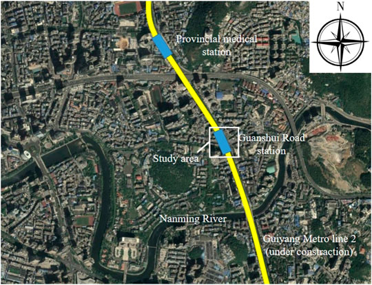
FIGURE 1. Schematic diagram of the location of Guanshui Road Station
According to the geological survey data, the upper covering layers of the transfer section are moderately weathered dolomite (T1a), highly weathered dolomite (T1a), plastic red clay (Q4el+dl), and miscellaneous fill (Q4ml) from bottom to top, respectively. The transfer section is mainly located in moderately weathered dolomite with surrounding rock of grade V, and part of the vault is located in highly weathered dolomite. The thickness of the strata above the vault varies greatly, ranging from 4 to 14 m. The rock mass is mostly of a block and layered structure, some are of a gravel and breccia structure.
Due to the complexity of the transfer section construction, it is very difficult to analyze its mechanical effect theoretically (Gan et al., 2014; Klotoé and Bourgeois, 2019; Oh et al., 2019; Wang et al., 2022). In order to determine the construction scheme of the transfer section, this paper adopted the numerical simulation method and used MIDAS NX finite element software to establish a three-dimensional numerical model to analyze the stress, displacement, and plastic zone distribution of the surrounding rock-supporting system during the excavation, so as to provide guidance for the construction.
According to the geological conditions of the project, the strata were simplified as homogeneous and horizontal. Figure 2A is the three-dimensional geological model of the transfer section, and Figure 2B is a model of the cross passage and the main tunnel. The negative direction of the X axis is the tunneling direction of the cross passage, the positive direction of the Y axis is the large mileage direction of the main tunnel, and the positive direction of Z axis is vertical upward.
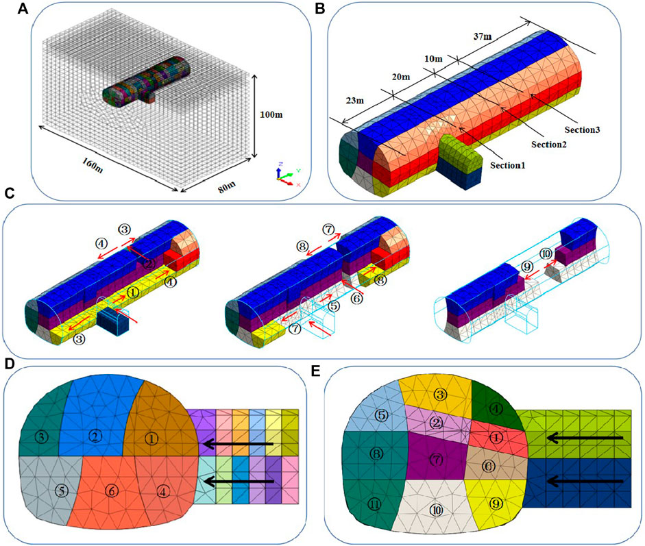
FIGURE 2. Finite element model and construction steps (A) Finite element model, (B) model of the cross passage and the main tunnel (C) steps of the double-holes interval pillar method, (D) steps of the sector expansion method, and (E) steps of the gate climbing method.
The distance from the left and right boundary of the model to the left and right side wall of the main tunnel is 69 m (about three times the width of the tunnel). The distance from the bottom boundary to the inverted arch of the main tunnel is 58 m (about three times the height of the tunnel), and the distance from the upper boundary to the tunnel vault is 23 m. The model takes the dimensions of 160 m × 80 m×100 m in the three directions of X, Y, and Z, with a total of 110,515 units and 20,846 nodes. The soil and rock are simulated by the solid element. The primary support, which is applied around the tunnel boundary permanently, is simulated by the plate element with a thickness of 300 mm. The temporary support, which is applied around each heading hole and will be removed after the temporary support is closed into a ring, is simulated by the plate element with a thickness of 200 mm.
The upper surface of the model is the free surface, the vertical displacement constraint is adopted for the bottom boundary, and the horizontal displacement constraint is adopted for the other four boundaries.
According to the survey data of Guanshui Road subway station provided by the exploration department, the physical and mechanical parameters of the soil are shown in Table 1. The constitutive model of soil is simulated through the Mohr-Column model (Lee et al., 2012; Singh and Singh, 2012; Singh and Mandal, 2019; Zhang et al., 2019). The physical and mechanical parameters of the supporting structure are also shown in Table 1, the elastic modulus can be calculated according to Eq. 1.
where E is the equivalent elastic modulus of the primary support, E0 is the elastic modulus of the sprayed concrete, Eg is the elastic modulus of steel, Sg is the cross-sectional area of the steel bar, and S0 is the cross-sectional area of the concrete.
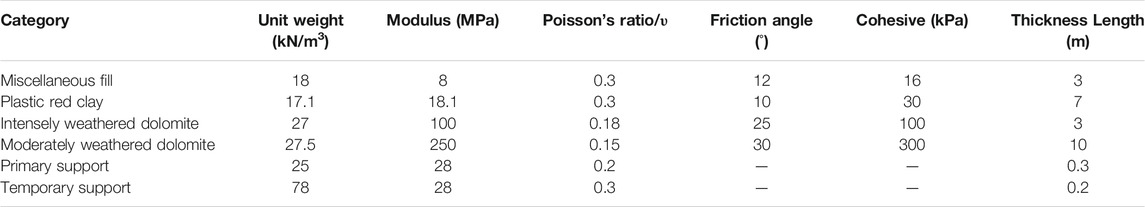
TABLE 1. Physical and mechanical parameters of each stratum and support.
In order to determine the construction scheme for the transfer section between the cross passage and the main tunnel of Guanshui Road Station, three different construction methods, namely, the double-holes interval pillar method, sector expansion method, and gate climbing method were simulated. And the optimal construction method was determined based on the comparisons, including the stress and displacement of the surrounding rock and the supporting system, and the distribution of the plastic zone of the surrounding rock caused by different methods.
In the double-holes interval pillar method, the cross passage and main tunnel are excavated by step method and double side heading method, respectively. The main construction steps of this method are shown in Figure 2C.
1) The upper and middle heading holes of the main tunnel’s right side are excavated towards the large mileage and the support after finishing the excavation of the upper steps of the cross passage is created. As shown in Figure 2C, step ①;
2) After the upper heading hole of the main tunnel is excavated to 4D (D is the width of the cross passage), the upper and middle heading holes of the central core soil are excavated to the left of the main tunnel and an internal passage connecting the left and right heading holes of the main tunnel is formed and supported. As shown in Figure 2C, step ②;
3) The upper and middle heading holes of the main tunnel’s right side near the transfer section towards the large mileage are excavated. At the same time, the upper and middle heading holes of the main tunnel’s left side near the internal passage towards the small mileage are excavated and supported. As shown in Figure 2C, step ③;
4) From the internal passage, the upper and middle heading holes of the main tunnel’s left side towards the small mileage and right side towards the large mileage are excavated and supported. As shown in Figure 2C, step ④;
5) When the excavation distance of step ④ reaches 12 m, the lower heading holes of the cross passage and the double sides of main tunnel are excavated and supported. As is shown in Figure 2C, steps ⑤→⑥→⑦→⑧;
6) The central core soil from the internal passage to the large and small mileage is excavated and supported. As shown in Figure 2C, steps ⑨→⑩.
In the sector expansion excavation method, the rock of the transfer section is excavated by multiple sector-shaped excavation bodies, as is shown in Figure 2D. The detailed steps are as follows: 1) When the upper step of the cross passage is excavated to the junction between the cross passage and main tunnel, a portal arch is erected in the cross passage. 2) The transfer section is excavated, and the upper step of the transfer section is divided into three sector-shaped excavation bodies. The excavation width is equal to the width of the cross passage, and the portal arch and primary support are erected immediately after excavation. 3) The lower step of the cross passage and the main tunnel are excavated by the sequence mentioned above. 4) The annular steel support is erected along the main tunnel and the upper arch of the station is closed into a ring through multiple expansion excavation, then construction of the transfer section is completed.
The gate climbing method is a method to excavate the main tunnel at a gradient of 12% along the excavation direction of the cross passage during the construction of the transfer section. Then the reverse excavation method is used to excavate the rock of the transfer section as shown in Figure 2€. The specific steps are as follows: 1) The cross passage section is excavated in full. When it is excavated to the junction part, three portal arches are erected at the junction between the cross passage and the main tunnel. 2) The transfer section is excavated upwards along the excavation direction of the cross passage with the gradient of 12%, the width of excavation part is the same as that of the cross passage and is excavated to the contour line on the other side of the main tunnel. 3) The transfer section is totally divided into eight parts for excavation. Then the portal arch and primary support are erected immediately. 4) The annular steel supports along the contour line of the top of the main tunnel are erected after every step of excavation. Finally, the steel support is closed into a ring and the construction of the transfer section is complete.
In order to compare the influence of different methods on the supporting structure and surrounding rock of the cross passage-main tunnel, the stress, displacement of the surrounding rock-supporting system, and the distribution of the plastic zone of surrounding rock were analyzed by selecting three sections, namely section 1 (the center of the transfer section) and sections 2 and 3 (from the position of 20 and 30 m away from the transfer section, respectively). The positions of the three selected sections are shown in Figure 2B.
Figure 3 shows the vertical and horizontal displacement nephograms of the supporting structures of the cross passage and the main tunnel after the construction of the double-holes interval pillar method, sector expansion method, and gate climbing method, respectively. In the figure, the vertical displacement is positive in the upward and negative in the downward direction. The horizontal displacement is negative in the heading direction of the cross passage. The maximum vertical displacements of the three methods are all located at the arch bottom of the main tunnel with the small mileage boundary, which are 5.84, 5.66, and 5.78 mm, respectively. The minimum vertical displacements are all located at the vaults of the main tunnel with the small mileage boundary, which are −5.71, −5.82, and −5.86 mm, respectively. The maximum horizontal displacements are located at the arches on both sides of the main tunnel with the small mileage boundary, which are 3.21 and −3.45 mm, 3.14 and −2.86 mm, and 2.92 and −2.75 mm, respectively.
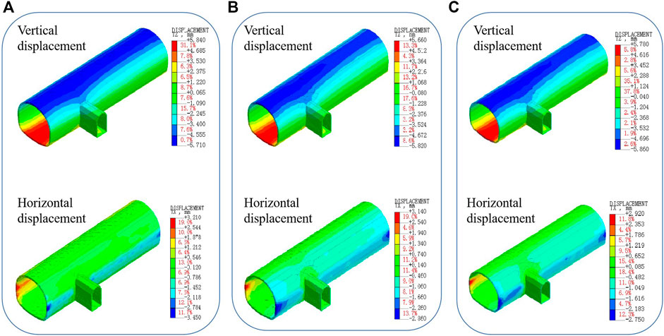
FIGURE 3. Displacement nephogram after construction (A) The double-holes interval pillar method, (B) the sector expansion method, and (C) the gate climbing method.
Figure 4A shows that the settlements vary with the construction steps for three sections under the double-holes interval pillar method. As shown in Figure 2B and section 1 is at the right side of the cross passage, section 3 is the cross section of the internal passage, and section 2 is at the middle between section 1 and section 3. In section 3, the construction of upper, medium, and lower heading holes of the internal passage are completed in steps 23, 61, and 85, respectively.
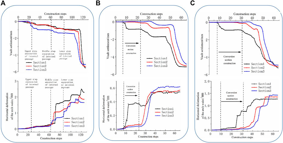
FIGURE 4. Deformation curve of the supporting structure under each method (A) The double-holes interval pillar method, (B) the sector expansion method, and (C) the gate climbing method
Figure 4A shows that before the excavation of the central core soil, the vault settlements of sections 1, 2 were −0.89 and −1.21 mm, respectively. With the excavation of the left and right heading holes, the vault settlements increase gradually. When the construction steps reach 116 (section 1) and 112 (section 2), respectively, the upper step of the central core soil can be excavated, then the vault settlements increase sharply and finally reach −5.49 and −5.44 mm, respectively. The upper heading hole of the internal passage can be excavated at step 23, causing the vault settlement of the internal passage to increase to −1.11 mm rapidly. With the excavation of the left and right heading holes, the vault settlement of the internal passage gradually increases. The central core soil can be excavated at step 106, resulting in a sharp increase in the vault settlement of the internal passage, which finally stabilizes at −5.13 mm and is less than the vault settlement of section 1 (−5.49 mm).
In Figure 4A, the hance deformation of section 1 slowly increases with the excavation of the left and right upper heading holes and the upper steps of the internal passage. The middle heading hole on the left side is excavated at step 65, causing the hance deformation to rapidly increase to 1.61 mm. When the construction steps reach 100 and 120, the left lower heading hole and the lower step of the central core soil are excavated, respectively, causing the deformation to increase again, and finally stabilize at 2.49 mm. The law of hance horizontal deformation in section 2 is very similar to that in section 1, with three obvious changes, corresponding to the excavation of the middle heading hole on left side, the lower heading hole on left side, and the lower step of the central core soil, and finally stabilizes at 1.86 mm. The hance deformation of section 3 firstly occurs during the excavation of the middle step of the internal passage, then changes significantly during the excavation of the left and right heading holes, and finally stabilizes at 1.66 mm.
Figure 4B shows the settlement curve of the three sections with the construction step after the construction of the sector expansion method is completed. The vault settlement of section 1 reaches −0.91 mm after the construction of the transfer section. When the construction step reaches 46, the central core soil in the middle of the transfer section is excavated, the vault settlement of section 1 increases sharply, and finally stabilizes at −5.09 mm. The vault settlement of sections 2, 3 increases slowly during the construction of the transfer section, which indicates that the construction of the transfer section has little influence on the vault settlement of sections 2, 3. With the excavation of the main tunnel, the vault settlements of sections 2, 3 are similar to those of section 1, and finally stabilizing at −5.01 and −4.81 mm, respectively.
Figure 4B also shows the curve of the hance horizontal displacement of the three sections with the construction step after the completion with the sector expansion method. The upper three sector expanding excavated bodies are excavated at step 10, and the hance deformation of section 1 rapidly increases to 0.36 mm. The middle heading holes on the left and right side of the main tunnel are excavated at step 30, and the value deformation of section 1 increases sharply. Finally, with the completion of the secondary lining construction, the deformation reaches a stable level of about 0.55 mm. The laws of the horizontal hance deformation of sections 2, 3 are similar, which all increase obviously at the excavation stage of left and right heading holes of the main tunnel, and finally stabilize at 0.57 and 0.62 mm, respectively, with the completion of secondary lining construction.
Figure 4C shows the settlement variation of the three sections with construction steps after the completion under the gate climbing method. The variation of the three sections is similar to that of the sector expansion method, and the final vault settlement is stable at −5.21, −4.99, and −4.91 mm, respectively.
Figure 4C also shows the curve of the hance horizontal displacement of the three sections with the construction step after the completion with the gate climbing method. With the excavation of the upper “climbing body,” the hance horizontal deformation of section 1 rapidly increases to 0.58 mm. After completing the construction of the transfer section, it is transferred to the construction of the main tunnel. Affected by this, the deformation of the surrounding rock continues to increase and finally stabilizes at 1.26 mm. The laws of the hance deformation of section 2 and section 3 are basically the same, and both increase obviously when excavating the heading holes and the central core soil of the main tunnel. After the secondary lining, the final deformation reaches 1.37 and 1.46 mm, respectively.
Maximum and minimum primary stress have an important influence on the stability of the tunnel supporting structure. Figure 5 shows the maximum and minimum primary stress vector diagrams of the supporting structure of the transfer passage-main tunnel after the construction under each method.
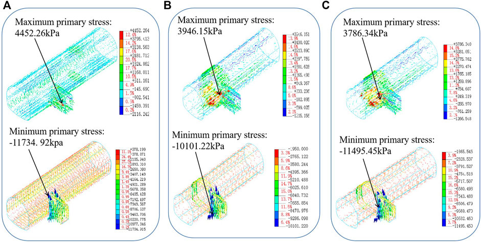
FIGURE 5. Primary stress of supporting structure under each method (unit: kPa) (A) The double-holes interval pillar, (B) the sector expansion method, and (C) the gate climbing method.
Figure 5A shows that after the construction of the double-holes interval pillar method, the direction of the maximum primary stress is distributed along the axis of the main tunnel in most areas, but the direction of the large primary stress becomes disordered near the horsehead gate arch bottom in the transfer section. The maximum primary stress is 4,452.26 kPa, which indicates that the supporting structure at the bottom of the horsehead gate arch bottom is in tension. The small primary stress of the supporting structure is distributed annularly along the tunnel in most areas, stress concentration occurs at the sidewall on both sides of the horsehead gate, and the small primary stress direction near the horsehead gate and the main tunnel becomes disordered. The minimum primary stress is −11,734.92 kPa, which indicates that the supporting structure at the spandrel and sidewall on both sides of the horsehead gate are under pressure.
It can be seen from Figures 5B,C that with the construction of the sector expansion method and gate climbing method, the large primary stress of the supporting structure is distributed along the axial of the main tunnel. Different from the double-holes interval pillar method, the large primary stress of the supporting structures of sector expansion excavation method and gate climbing method are distributed alternately in positive and negative directions at the arch bottom of the transfer section, and the stress concentration occurs at the arch bottom of the main tunnel and horsehead gate. The maximum primary stresses of the two methods are 3,946.15 and 3,786.34 kPa, respectively, indicating that the arch bottom supporting structure of the transfer section is in tension.
In addition, it can be seen from Figures 5B,C that after completing the construction under the sector expansion method and gate climbing method, the small primary stress of the supporting structure is distributed annularly along the tunnel. Stress concentration occurs at the positions of the transfer section between the cross passage and the main tunnel. The minimum primary stresses of the two methods are −10,101.22 and −11,495.45 kPa, respectively, which indicates that the spandrel and sidewall supporting structure on both sides of the horsehead gate are under pressure.
The plastic zone has an important influence over the stability of the tunnel surrounding rock and the supporting system. Figure 6A shows the distribution of the surrounding rock plastic zone after the application of the double-holes interval pillar method in construction. It can be seen that the surrounding rock plastic zone of the main tunnel is mainly distributed at the hance and arch foot on both sides of the main tunnel with a maximum plastic zone radius of 3.11 m. However, the plastic zone of the side wall of the horsehead gate in the transfer section is much wider with a radius of 6.38 m. It also shows that the plastic zone distribution of surrounding rock plastic strain is above 300 με after construction with the double-holes interval pillar method. It can be seen that the maximum plastic strain of the surrounding rock appears at the spandrel on both sides of the horsehead gate where the cross passage connects with the main tunnel (see the circular area in the figure), and the maximum equivalent plastic strain value is 0.001189.
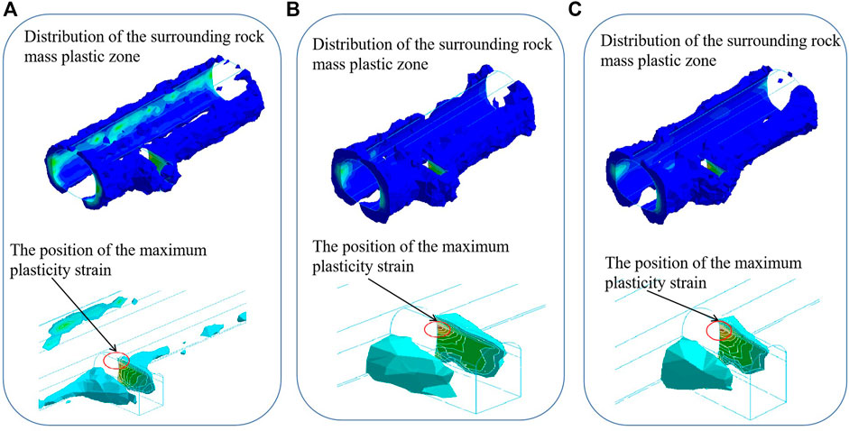
FIGURE 6. Distribution of the surrounding rock plastic zone under each method (A) The double-holes interval pillar, (B) the sector expansion method, and (C) the gate climbing method
Figures 6B,C give the distribution of the plastic zone of the surrounding rock after the construction under the sector expansion method and the gate climbing method, respectively. It can be seen that the plastic zone distribution of these two methods is similar to the double-holes interval pillar method, but the distribution range is slightly larger. The radii of the maximum plastic zone of the main tunnel are 3.40 and 3.21 m, respectively. The radii of the maximum plastic zone of the side walls of the cross passage are 7.08 and 6.84 m, respectively. The plastic zone distribution of the surrounding rock with plastic strain above 300 με after the construction under the sector expansion method and the gate climbing method are also shown in Figures 6B,C, respectively. It can be seen that the maximum plastic strain of the two methods occurs in the position of the side wall on both sides of the horsehead gate where the cross passage connects with the main tunnel, which is different from the double-holes interval pillar method. The maximum equivalent plastic strain values are 0.001425 and 0.001229, respectively.
Figure 7 shows the ground settlement curves corresponding to the position of section 1 after the construction under the three methods. Three points can be seen from the figure that: 1) the width of the settlement trough caused by the three methods is relatively similar, all around 60 m, 2) the maximum ground settlement caused by the three methods did not occur above the vault of the main tunnel, but appears at the position corresponding to the intersection of the main tunnel and the cross passage, and 3) the maximum ground settlement caused by the gate climbing method is the largest, which is 5.05 mm, the sector expansion method is 3.72 mm, and the smallest is the double-hole interval pillar method, which is 3.32 mm. Thus, it could be concluded that the double-holes interval pillar method is more advantageous for controlling ground settlement than the other two methods.
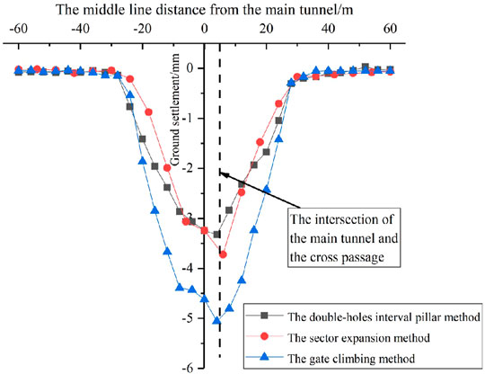
FIGURE 7. The comparison of the ground settlement.
According to the analysis of section 4.2, the transfer section is the position where the strain of the support-surrounding rock structure is most concentrated. Therefore, the displacement of the transfer section under the three construction methods and the strain state of the support-surrounding rock structure of horsehead gate are compared and analyzed.
Table 2 displays the maximum and minimum displacements in the three directions of X, Y, and Z caused by the three construction methods. It can be seen that the displacements under the three methods are very close. And the position of each kind of displacements caused by each method are the same. The position of each kind of displacement are as follows: the maximum displacement in the direction of X caused by these three methods all occur at the left hance of the main tunnel, the minimum displacement in the direction of X caused by these three methods all occur at the right hance of the main tunnel, the maximum displacement in the direction of Y caused by these three methods all occur at the left wall of the horsehead gate, the minimum displacement in the direction of Y caused by these three methods all occur at the right wall of the horsehead gate, the maximum displacement in the direction of Z caused by these three methods all occur at the right arch bottom of the main tunnel, and the minimum displacement in the direction of Z caused by these three methods all occur at the right vault of the main tunnel.
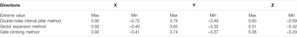
TABLE 2. Comparison of the maximum and minimum displacement of the transfer section (unit: mm).
Table 3 shows the maximum value of the maximum principal strain, the minimum principal strain, the maximum shear strain of the supporting structure of the horsehead gate of the transfer section, and the positions where they occur after the construction under different methods. It can be concluded from Table 3 that: 1) the maximum principal strain value caused by the double-holes interval pillar method is the largest, and the maximum principal strain occurs at the arch foot of the horsehead gate. While the maximum principal strain of the other two methods occurs at the arch bottom of the main tunnel. 2) The minimum principal strain caused by the gate climbing method occurs at the arch foot of the horsehead gate, while the minimum principal strain of the other two methods occurs at the spandrel of the horsehead gate. The minimum principal strain value caused by the double-holes interval pillar method is the largest. ) The maximum shear strain caused by the double-holes interval pillar method occurs at the spandrel of the horsehead gate, while the other two methods occur at the arch foot of the horsehead gate. The maximum shear strain caused by the sector expansion method is the largest. Hence, in general term, the strain value of the supporting structure caused by the double-holes interval pillar method is larger.
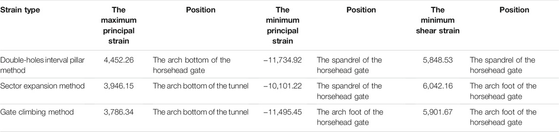
TABLE 3. Comparison of the strain of the supporting structure (unit: kPa).
The plastic zone is an important indicator for judging the stability of the surrounding rock when tunneling. Table 4 shows the distribution of the plastic zone of the surrounding rock after the construction under the three methods. Table 4 shows that, among the three methods, the maximum radius of the plastic zone of the main tunnel, the maximum radius of the plastic zone of the transfer section, and the maximum equivalent plastic strain value caused by the double-holes interval pillar method are the smallest.
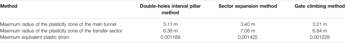
TABLE 4. Comparison of the plastic zone of surrounding rock after construction.
In summary, although the strain value of the supporting structure caused by the double-holes interval pillar method is large, it has advantages in controlling the ground settlement and the plastic zone range of the surrounding rock. In addition, compared with the other two methods, the double-holes interval pillar method can be used for the construction of the transfer section to reduce the construction risk because it can prevent high-altitude operation by avoiding the erection of a scaffold. At the same time, this method has multiple working spaces and can operate simultaneously, which can shorten the construction period and reduce the construction cost. Therefore, from the comprehensive analysis of the numerical simulation results and the construction technologies, the use of the double-holes interval pillar method for the construction of the transfer section is recommended.
Based on the results of the numerical analysis, the construction of the transfer section of the Guanshui Road Station is carried out with the double-holes interval pillar method.
In order to ensure the construction safety of the transfer section, the ground settlement and the internal deformation of the main tunnel are tracked and monitored during the construction process. Figure 8 shows the layout of monitoring points of ground settlement at the Guanshui Road Station.
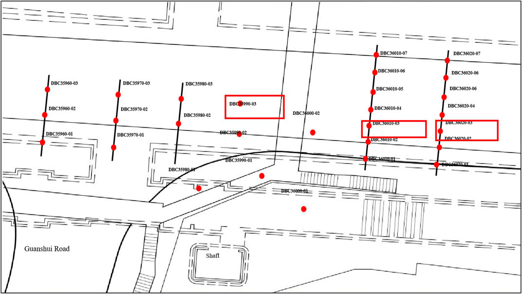
FIGURE 8. The layout of monitoring points of Guanshui Road Station.
Due to the large number of monitoring points arranged on site, only the settlement data from the ground settlement monitoring points DBC35990-03, DBC36010-03, and DBC36020-03 corresponding to sections 1– 3 are selected for analysis (Figure 8).
Figure 9A shows the settlement curve of point DBC35990-03 (section 1). When the construction starts, the excavation of the cross passage is carried out. The settlement of this point increases to 0.6 mm (point A in Figure 9A); after 17 days, the transfer section is excavated and the settlement increases quickly to 2.2 mm [point B in 9(A)] as the construction face is close to the monitoring point. On the 27th days of monitoring, as the construction of the transfer section is completed and the excavation of the main tunnel is started to the direction of the large mileage, the ground settlement increases slowly to 3.1 mm (point C in Figure 9A); on the 60th day of monitoring, the construction of the left and right heading holes is completed and the central core soil is excavated. As a result, the ground settlement is significantly increased, and the final settlement is stable at 6.4 mm (point D in Figure 9A).

FIGURE 9. Variation of ground displacement of: (A) Section 1, (B) Section 2, and (C) Section 3.
Figure 9B shows the settlement curve of point DBC36010-03 (section 2). In the initial stage of monitoring, because the construction face is far from monitoring point DBC36010-03, the settlement is small and slowly increases to 0.9 mm (as shown in point A of Figure 9B). On the 30th days of the monitoring process, the construction face gradually reaches the position of section 2. Affected by this, the settlement increases quickly and reaches 2.4 mm (as shown in point B of Figure 9B). On the 60th days, the central core soil is excavated. As a result, the ground surface settlement speed increases significantly, and the final settlement stabilizes at 5.3 mm (as shown in point C of Figure 9B).
Figure 9C shows the settlement curve of the monitoring point DBC36020-03 (section 3). In the initial stage of monitoring, because the construction face is far from the monitoring point, the settlement is small and slowly increases to 0.6 mm (as shown in point A of Figure 9C). On the 40th day of the monitoring process, excavation begins in the internal passage. At this time, the construction face is close to the monitoring point and the settlement speed of the point increases, finally the ground settlement rapidly increases to 2.1 mm (as shown in point B of Figure 9C). On the 50th day, because the excavation of the left and right heading holes has a smaller effect on this point, the ground settlement speed decreases and slowly increases to 2.5 mm (as shown in point C of Figure 9C). On the 60th day, the excavation of the central core soil has begun, the ground surface settlement increases significantly, and the final settlement stabilizes at 4.8 mm (as shown in point D of Figure 9C).
The corresponding deformation monitoring points of sections 1–3 are GDC35990-1, GDC36010-1, and GDC36020-1, respectively, and the horizontal deformation monitoring points are SDJ35990-1, SDJ36010-1, and SDJ36020-1, respectively.
Figure 10A shows the vault settlement curve of point GDC35990-1 (section 1) and horizontal deformation curve of point SDJ359901. The deformation of the monitoring points GDC35990-1 and SDJ36000-1 are monitored after the completion of supporting construction of section 1. For the monitoring point GDC35990-1, in the initial stage of monitoring, because the support at this section has just been completed, the vault settlement increases slightly and reaches to 1.3 mm (as is shown in point A of Figure 10A). Then, with the excavation of the right and left heading holes of the main tunnel, the settlement is gradually increased to 3.2 mm (as is shown in point B of Figure 10A). As the monitoring progress reaches the 60th days, the central core soil is excavated. The vault settlement increases significantly and the final settlement stabilizes at 9.1 mm (as is shown in point C of Figure 10A). For monitoring point SDJ36000-1, the horizontal deformation speed is stable during the first 60 days. Until the 60th days of the monitoring process, the horizontal deformation increases to 3.2 mm (as is shown in point B of Figure 10A). Then, with the excavation of the central core soil, the horizontal deformation increases significantly and the final deformation stabilizes at 6.1 mm (as is shown in point D of Figure 10A).
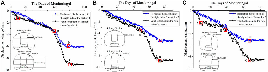
FIGURE 10. Variation of displacement of the tunnel: (A) Section 1, (B) Section 2, and (C) Section 3.
Figure 10B shows the vault settlement curve of point GDC36010-1 (section 2) and horizontal deformation curve of point SDJ36010-1. The deformation of the monitoring points GDC36010-1 and SDJ36010-1 are monitored after the completion of supporting construction of section 2. For monitoring point GDC36010-1, during the excavation of the right and left heading holes of the main tunnel, the settlement speed of the vault is stable and the settlement increases to 3.2 mm gradually (as is shown in point A of Figure 10B). On the 50th day of the monitoring process, the excavation of the central core soil has begun. The vault settlement speed increases significantly and the final settlement stabilizes at 8.8 mm (as is shown in point B of Figure 10B). The horizontal deformation speed of monitoring point SDJ36010-1 is stable during the whole construction process and finally stabilizes at 5.4 mm (as is shown in point C of Figure 10B).
Figure 10C shows the vault settlement curve of point GDC36020-1 (section 3) and horizontal deformation curve of point SDJ36020-1 (section 3). The deformation of the monitoring points GDC36020-1 and SDJ36020-1 are monitored after the completion of supporting construction of section 3. For monitoring point GDC36020-1, in the initial stage of monitoring, because the supporting structure of the internal passage has just been completed, the vault settlement shows a small rapid increase to 2.1 mm (as shown in point A of Figure 10C). Then, the vault settlement has a period of fluctuation and increases to 3.1 mm (as is shown in point B of Figure 10C) with the excavation of the right and left heading holes of the main tunnel. On the 40th day of the monitoring progress, the central core soil is excavated and the vault settlement speed increases significantly. The final settlement is stabilized at 8.6 mm (as shown in point C of Figure 10C). For monitoring point SDJ36020-1, the deformation law is similar to that of section 2. The horizontal deformation speed of monitoring point SDJ36020-1 is stable during the whole construction process and finally stabilizes at 5.2 mm (as shown in point D of Figure 10C).
Table 5 shows the comparison of the final deformation between the numerical simulation results and the monitoring results among the nine monitoring points in Figures 9, 10. It can be seen that the numerical simulation calculation is smaller than the monitoring deformation at each point. This is mainly due to the following two reasons, on the one hand, for the sake of simplicity, the soil is assumed to be a homogeneous and isotropic continuous medium in the numerical calculation, while the actual soil is a heterogeneous and anisotropic discontinuous medium, so the numerical simulation results are smaller. On the other hand, the surrounding rock of the transfer passage is disturbed by the construction many times during the construction process. The weak structural planes and cracks in the surrounding rock are further cracked after being disturbed, resulting in the gradual deterioration of the surrounding rock mechanical properties. The simulation could not consider the deterioration of the mechanical properties in the surrounding rock after the construction disturbance, which also made the numerical simulation results smaller.
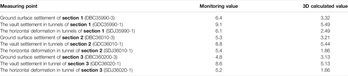
TABLE 5. Comparison between the monitoring data and numerical simulation data (unit: mm).
Although there are some differences between the numerical simulation results and the measured results, in general, the monitoring ground settlement is 30 mm less than the control value, and the monitoring horizontal displacement in the tunnel is also 20 mm less than the control value. Therefore, it is safe and feasible to use the double-holes interval pillar method to construct the transfer section of the Guanshui Road Station.
This paper adopted three methods, the double-holes interval pillar method, sector expansion method, and gate climbing method to carry out a series of numerical analyses for the Guanshui Road Station of Guiyang City Metro line 2 in Guizhou Province, China on the construction of the transfer section. By comparing the calculation results of the three methods, the optimal construction scheme of the transfer section was determined. The main conclusions are as follows:
1) Among the three methods, local stress concentration occurred in the position of the horsehead gate of the transfer section. The maximum ground surface settlement did not occur above the vault of the main tunnel, but appeared on the ground surface corresponding to the horsehead gate where the main tunnel met the cross passage. Therefore, the horsehead gate is the key location for construction reinforcement.
2) The ground surface settlement, the displacement of the tunnel, and the plastic zone caused by the double-holes interval pillar method were the smallest, and the method could reduce the construction risk, shorten the construction period, and reduce project cost. Therefore, using the double-holes interval pillar method is a better way for the construction of the transfer section.
3) The comparison between the monitoring deformation data and the numerical simulation results of the double-holes interval pillar method shows that the numerical results were smaller than those of the monitoring results. There are two reasons. On the one hand, the soil was assumed to be a homogeneous, isotropic, and continuous medium during the numerical simulation. On the other hand, the numerical simulation could not simulate the deterioration of the mechanical properties of the surrounding rock after construction disturbance.
4) Although the numerical simulation results were different from the monitoring deformations at each point, the ground settlement caused by the double-holes interval pillar method was less than the ground settlement control value. The ground settlement and the horizontal displacement of the tunnel were 30 and 20 mm less than the control value, respectively. Therefore, it is feasible to use the double-holes interval pillar method to construct the transfer section of Guanshui Road Station of Guiyang City Metro line 2.
The original contributions presented in the study are included in the article/Supplementary Material, further inquiries can be directed to the corresponding authors.
ZS conceived and designed the methods, provided the guide of monitoring and theoretical research for the study, and economically supported the project. PZ and JW completed the numerical model, data analysis, and the writing of the paper manuscript. ZP and ZC provided the monitoring materials and completed the data collection.
The paper is supported by the National Natural Science Foundation of China (52178393 and 52178354), the Housing and Urban-Rural Construction Science and Technology Planning Project of Shaanxi Province (No. 2019-K39), and the Innovation Capability Support Plan of Shaanxi—Innovation Team (No. 2020TD-005).
The authors declare that the research was conducted in the absence of any commercial or financial relationships that could be construed as a potential conflict of interest.
All claims expressed in this article are solely those of the authors and do not necessarily represent those of their affiliated organizations, or those of the publisher, the editors and the reviewers. Any product that may be evaluated in this article, or claim that may be made by its manufacturer, is not guaranteed or endorsed by the publisher.
Bobet, A. (2001). Analytical Solutions for Shallow Tunnels in Saturated Ground. J. Eng. Mech. 127 (12), 1258–1266. doi:10.1061/(asce)0733-9399(2001)127:12(1258)
Cao, L., Fang, Q., Zhang, D., and Chen, T. (2018). Subway Station Construction Using Combined Shield and Shallow Tunnelling Method: Case Study of Gaojiayuan Station in Beijing. Tunnelling Underground Space Technology 82, 627–635. doi:10.1016/j.tust.2018.09.010
Comodromos, E. M., Papadopoulou, M. C., and Konstantinidis, G. K. (2014). Numerical Assessment of Subsidence and Adjacent Building Movements Induced by TBM-EPB Tunneling. J. Geotech. Geoenviron. Eng. 140 (11), 04014061. doi:10.1061/(asce)gt.1943-5606.0001166
Daraei, A., and Zare, S. (2018). A New Strain-Based Criterion for Evaluating Tunnel Stability. Geomech. Eng. 16 (2), 205–215. doi:10.12989/gae.2018.16.2.205
Djelloul, C., Karech, T., Demagh, R., Limam, O., and Martinez, J. (2018). 2D Numerical Investigation of Twin Tunnels-Influence of Excavation Phase Shift. Geomech. Eng. 16 (3), 295–308. doi:10.12989/gae.2018.16.3.295
Dong, Z., Kuo, C., Yin, J., Wen, S., Liu, G., and Gou, Y. (2021). Examination of Longitudinal Seismic Vulnerability of Shield Tunnels Utilizing Incremental Dynamic Analysis. Front. Earth Sci. 9, 995. doi:10.3389/feart.2021.779879
Fan, J., Jiang, D., Liu, W., Wu, F., Chen, J., and Daemen, J. (2019). Discontinuous Fatigue of Salt Rock with Low-Stress Intervals. Int. J. Rock Mech. Mining Sci. 115 (3), 77–86. doi:10.1016/j.ijrmms.2019.01.013
Fan, J. Y., Liu, W., Jiang, D. Y., Chen, J., Tiedeu, W. N., and Daemen, J. J. K. (2020a). Time Interval Effect in Triaxial Discontinuous Cyclic Compression Tests and Simulations for the Residual Stress in Rock Salt. Rock Mech. Rock Eng. 53 (9), 4061–4076. doi:10.1007/s00603-020-02150-y
Fan, S.-y., Song, Z.-p., Zhang, Y.-w., and Liu, N.-f. (2020b). Case Study of the Effect of Rainfall Infiltration on a Tunnel Underlying the Roadbed Slope with Weak Inter-layer. KSCE J. Civ Eng. 24 (5), 1607–1619. doi:10.1007/s12205-020-1165-0
Galli, G., Grimaldi, A., and Leonardi, A. (2004). Three-dimensional Modelling of Tunnel Excavation and Lining. Comput. Geotechnics 31 (3), 171–183. doi:10.1016/j.compgeo.2004.02.003
Gan, P. L., Tang, X. W., Shen, W. M., and Wang, H. Y. (2014). Numerical Analysis on Interaction Induced by Crosswise Tunneling. Amm 580-583, 1076–1080. doi:10.4028/www.scientific.net/amm.580-583.1076
Gaspari, G. M., Zanoli, O., and Pescara, M. (2010). “Three-dimensional Modelling of the Tunnel Intersections in Weak Rock Mass on the Kadikoy-Kartal Metro Line of Istanbul,” in ISRM International Symposium-EUROCK, Lausanne, Switzerland, June 15-18.
Hsiao, F. Y., Yu, C. W., and Chern, J. C. (2004). Feedback Analysis on Stability of Intersection Area of Seven Tunnels Based on Monitoring and Construction Data. Chin. J. Rock Mech. Eng. 23 (22), 5012–5018.
Hsiao, F. Y., Wang, C. L., and Chern, J. C. (2009). Numerical Simulation of Rock Deformation for Support Design in Tunnel Intersection Area. Tunnelling Underground Space Technology 24 (1), 14–21. doi:10.1016/j.tust.2008.01.003
Janda, T., Šejnoha, M., and Šejnoha, J. (2018). Applying Bayesian Approach to Predict Deformations during Tunnel Construction. Int. J. Numer. Anal. Methods Geomech 42 (15), 1765–1784. doi:10.1002/nag.2810
Jiang, D., Fan, J., Chen, J., Li, L., and Cui, Y. (2016). A Mechanism of Fatigue in Salt under Discontinuous Cycle Loading. Int. J. Rock Mech. Mining Sci. 86 (7), 255–260. doi:10.1016/j.ijrmms.2016.05.004
Kang, Y., Fan, J., Jiang, D., and Li, Z. (2021). Influence of Geological and Environmental Factors on the Reconsolidation Behavior of fine Granular Salt. Nat. Resour. Res. 30 (1), 805–826. doi:10.1007/s11053-020-09732-1
Khademian, A., Abdollahipour, H., Bagherpour, R., and Faramarzi, L. (2017). Model Uncertainty of Various Settlement Estimation Methods in Shallow Tunnels Excavation; Case Study: Qom Subway Tunnel. J. Afr. Earth Sci. 134, 658–664. doi:10.1016/j.jafrearsci.2017.08.003
Klotoé, C. H., and Bourgeois, E. (2019). Three Dimensional Finite Element Analysis of the Influence of the Umbrella Arch on the Settlements Induced by Shallow Tunneling. Comput. Geotech. 110, 114–121. doi:10.1016/j.compgeo.2019.02.017
Lee, Y.-K., Pietruszczak, S., and Choi, B.-H. (2012). Failure Criteria for Rocks Based on Smooth Approximations to Mohr-Coulomb and Hoek-Brown Failure Functions. Int. J. Rock Mech. Mining Sci. 56, 146–160. doi:10.1016/j.ijrmms.2012.07.032
Li, X., Yang, S., Wang, Y., Nie, W., and Liu, Z. (2021). Macro-micro Response Characteristics of Surrounding Rock and Overlying Strata towards the Transition from Open-Pit to Underground Mining. Geofluids 2021, 1–18. doi:10.1155/2021/5582218
Li, Y., Qi, T., Lei, B., Qian, W. P., and Li, Z. Y. (2019). Deformation Patterns and Surface Settlement Trough in Stratified Jointed Rock in Tunnel Excavation[J]. KSCE J. Civil Eng. 23, 3188–3199. 10.1007/s12205-019-0477-4.
Li, Y., Jin, X., Lv, Z., Dong, J., and Guo, J. (2016). Deformation and Mechanical Characteristics of Tunnel Lining in Tunnel Intersection between Subway Station Tunnel and Construction Tunnel. Tunnelling Underground Space Technology 56, 22–33. doi:10.1016/j.tust.2016.02.016
Li, Z., Soga, K., and Wright, P. (2016). Three-dimensional Finite Element Analysis of the Behaviour of Cross Passage between Cast-Iron Tunnels. Can. Geotech. J. 53 (6), 930–945. doi:10.1139/cgj-2015-0273
Lin, P., Zhou, Y., Liu, H., and Wang, C. (2013). Reinforcement Design and Stability Analysis for Large-Span Tailrace Bifurcated Tunnels with Irregular Geometry. Tunnelling Underground Space Technology 38 (9), 189–204. doi:10.1016/j.tust.2013.07.011
Liu, X., and Wang, Y. (2010). Three Dimensional Numerical Analysis of Underground Bifurcated Tunnel. Geotech. Geol. Eng. 28 (4), 447–455. doi:10.1007/s10706-010-9304-x
Lv, J., Li, X., Li, Z., Fu, H., and Fu, H. L. (2020). Numerical Simulations of Construction of Shield Tunnel with Small Clearance to Adjacent Tunnel without and with Isolation Pile Reinforcement. KSCE J. Civ Eng. 24 (1), 295–309. doi:10.1007/s12205-020-1167-y
Moosavi, E., Shirinabadi, R., Rahimi, E., and Gholinejad, M. (2018). Numerical Modeling of Ground Movement Due to Twin Tunnel Structure of Esfahan Subway, Iran. J. Min. Sci. 53 (4), 663–675. doi:10.1134/s1062739117042655
Oh, J., Moon, T., Canbulat, I., and Moon, J. S. (2019). Design of Initial Support Required for Excavation of Underground Cavern and Shaft from Numerical Analysis. Geomech. Eng. 17 (6), 573–581.
Ramos, S. G., Garcia-Fontanet, A., Ledesma, A., Raveendra, R., and Polo Orodea, T. (2018). Toronto-York Spadina Subway Extension Tunnelling under Schulich Building. Can. J. Civil Eng. 46 (2), 87–103. doi:10.1139/cjce-2017-0062
Singh, D. K., and Mandal, A. (2019). Dynamic Effect of Soil-Tunnel Interface under Dynamic Loading. Soil Mech. Found. Eng. 17. doi:10.1007/s11204-019-09575-w
Singh, M., and Singh, B. (2012). Modified Mohr-Coulomb Criterion for Non-linear Triaxial and Polyaxial Strength of Jointed Rocks. Int. J. Rock Mech. Mining Sci. 51, 43–52. doi:10.1016/j.ijrmms.2011.12.007
Sommer, C. G., Lehning, M., and Fierz, C. (2018). Wind Tunnel Experiments: Influence of Erosion and Deposition on Wind-Packing of New Snow. Front. Earth Sci. 6. doi:10.3389/FEART.2018.00004
Song, Z., Cao, Z., Wang, J., Wei, S., Hu, S., and Niu, Z. (2018b). Optimal Analysis of Tunnel Construction Methods through Cross Passage from Subway Shaft. Adv. Civil Eng. 2018, 1–14. doi:10.1155/2018/5181954
Song, Z. P., Li, S. H., Wang, J. B., Sun, Z. Y., Liu, J., and Chang, Y. Z. (2018a). Determination of Equivalent Blasting Load Considering Millisecond Delay Effect. Geomech. Eng. 15 (2), 745–754. doi:10.12989/gae.2018.15.2.745
Wang, J. B., Zhang, Q., Song, Z. P., Feng, S. J., and Zhang, Y. W. (2022). Nonlinear Creep Model of Salt Rock Used for Displacement Prediction of Salt Cavern Gas Storage. J. Energ. Storage. doi:10.1016/j.est.2021.103951
Wang, J., Wang, T., Song, Z., Zhang, Y., and Zhang, Q. (2021a). Improved Maxwell Model Describing the Whole Creep Process of Salt Rock and its Programming. Int. J. Appl. Mech. doi:10.1142/S1758825121501131
Wang, J., Wang, X., Zhang, Q., Song, Z., and Zhang, Y. (2021b). Dynamic Prediction Model for Surface Settlement of Horizontal Salt Rock Energy Storage. Energy 235, 121421. doi:10.1016/j.energy.2021.121421
Wang, J., Zhang, Q., Song, Z., and Zhang, Y. (2020). Creep Properties and Damage Constitutive Model of Salt Rock under Uniaxial Compression. Int. J. Damage Mech. 29 (6), 902–922. doi:10.1177/1056789519891768
Keywords: subway tunnel, transfer section, double-holes interval pillar method, sector expansion method, gate climbing method, numerical simulation, construction monitoring
Citation: Zhou PY, Wang JB, Song ZP, Cao ZL and Pei ZM (2022) Construction Method Optimization for Transfer Section Between Cross Passage and Main Tunnel of Metro Station. Front. Earth Sci. 10:770888. doi: 10.3389/feart.2022.770888
Received: 05 September 2021; Accepted: 28 January 2022;
Published: 04 March 2022.
Edited by:
Alexandre Chemenda, UMR7329 Géoazur (GEOAZUR), FranceReviewed by:
Ping Zhang, Luleå University of Technology, SwedenCopyright © 2022 Zhou, Wang, Song, Cao and Pei. This is an open-access article distributed under the terms of the Creative Commons Attribution License (CC BY). The use, distribution or reproduction in other forums is permitted, provided the original author(s) and the copyright owner(s) are credited and that the original publication in this journal is cited, in accordance with accepted academic practice. No use, distribution or reproduction is permitted which does not comply with these terms.
*Correspondence: J. B. Wang, Y3F1amJ3YW5nQDE2My5jb20=; Z. P. Song, c29uZ3pocHl0QHhhdWF0LmVkdS5jbg==
Disclaimer: All claims expressed in this article are solely those of the authors and do not necessarily represent those of their affiliated organizations, or those of the publisher, the editors and the reviewers. Any product that may be evaluated in this article or claim that may be made by its manufacturer is not guaranteed or endorsed by the publisher.
Research integrity at Frontiers
Learn more about the work of our research integrity team to safeguard the quality of each article we publish.