 Ying Cui
 Zhangjian Li
 Jun Fang
 Ben Zhao
94% of researchers rate our articles as excellent or good
Learn more about the work of our research integrity team to safeguard the quality of each article we publish.
Find out more
ORIGINAL RESEARCH article
Front. Earth Sci., 12 January 2023
Sec. Environmental Informatics and Remote Sensing
Volume 10 - 2022 | https://doi.org/10.3389/feart.2022.1114178
This article is part of the Research TopicAdvances in Development and Utilization of Underground SpaceView all 17 articles
This study analyzed the effects and influencing factors of shallowly-buried explosions in soil based on the design and implementation of static explosion experiments and numerical simulations. Based on the static explosion test data, a numerical analysis model of SPH-FEM was established and the explosion process and pit parameters in explosions shallowly buried in soil were analyzed. The results of numerical calculations and comparisons verified the effectiveness of the SPH-FEM method in simulating shallowly-buried explosions in soil. Furthermore, the similarities and differences between the SPH-FEM and ALE methods in the numerical simulation of the same explosion in the soil were assessed. The relationships between the blasting pit radius and explosive depth, and between the explosives weight and pit volume were analyzed. The empirical curve formula of the explosive depth and the crater radius with 9.35 kg of TNT explosive were obtained by mathematical fitting. The results showed that the SPH-FEM method was more refined and more computationally efficient than the ALE method to simulate shallow burial explosions in soil. The established empirical curve formula, which expressed the relationship between the explosive burial depth and the pit radius, effectively predicted the pit radius of the shallow burial explosion. With increasing explosive burial depth, the pit radius increased to the peak value and then decreased rapidly.
With the rapid development of China’s infrastructure, shallowly-buried explosions in soil are increasingly widely used in various types of engineering construction (Xie, 2007). Under blast loading, the initial natural density and moisture content of the soil changes, and various geological factors of the soil have a greater impact on the transmission of impulse in shallowly buried explosions. In addition, the process of shallowly-buried explosions in soil is more complex, both in terms of soil breakage and the propagation of blast products and blast shock waves (Qian, 2009; Wang et al., 2016; Liu et al., 2022a; Zhang et al., 2022a; Zhao et al., 2022; Liu et al., 2023; Zhang et al., 2022b). Therefore, establishing an effective method to describe the effects of shallowly buried explosions in soil is a scientific challenge that requires the study of the dynamic response and soil parameters of soils during blast loading (Du and Lu, 2011).
The blast crater formation of shallowly buried explosions is related to factors including soil type and explosive type. Liu et al. (2022b) used ANSYS/AUTODYN for modeling and simulation analysis to study the ground impact effect of the explosion in soil. They showed that the distribution of the blast stress wave changed with increasing burial depth of the charge ratio, with the central zone increasing rapidly, the surface zone decreasing rapidly, and the near-surface increasing gradually. Feng et al. (2020) summarized research on the effect of explosive near-surface explosion into pits and analyzed the formula for calculating the size of the blast crater formed by the explosion and the applicable conditions. Mu et al. (2010) studied explosive explosion cratering in soil and the accompanying stress wave propagation law at variable burial depths and established the stress wave propagation law in soil, the semi-empirical formula for explosion cratering, and the prediction formula for crater radius in a semi-closed explosion stage. Jia et al. (2017) conducted a series of field experiments in low moisture and saturated sandy soil to analyze the effect of explosive charge, explosive burial depth, and soil moisture content on the crater, and classified the crater pattern according to moisture content and burial depth. Yue et al. (2012) determined the relationship between charge volume and burial depth, as well as the volume of thrown funnel pits.
These previous studies in the experimental and numerical simulation of explosions in soil have provided many valid conclusions. However, when using the traditional ALE (Arbitrary Lagrange-Euler) finite element method to simulate explosions in soil, although the rapid propagation of shock waves in the soil medium is well simulated, it is difficult to accurately address large deformation aspects such as splash and crushing phenomenon after the explosion. Meanwhile, SPH (Smooth Particle Hydrodynamics), a meshless numerical method, deals relatively accurately with difficult problems such as large deformation and fluid flow; however, its disadvantages include long computational time, poor stability, and low accuracy. The coupled SPH-FEM method can consider the advantages of both and improve the computational efficiency while ensuring accuracy (Hu et al., 2015; Liang et al., 2017). The present study designed and conducted shallowly buried static explosion tests in soil to obtain the parameters of shallowly buried explosion craters. We also established a numerical model of shallowly buried explosion in soil based on the SPH-FEM and ALE methods, respectively. We then compared the numerical simulation and test results to verify the effectiveness of the SPH-FEM coupling algorithm for the numerical simulation of explosions in soil. Furthermore, by comparing the simulation results of SPH-FEM and ALE simultaneously with the error of the test results, we confirmed the superiority of the SPH-FEM method in simulating shallowly buried explosions in soil. Based on the numerical simulation results and through mathematical fitting, we established a shallowly buried explosion formula that expressed the explosive burial depth and the burst pit radius (a proportional burial depth of not more than .8 m/kg1/3).
The test bury pit site measuring 1,200 mm (length) × 900 mm (width) × 150 mm (height) was excavated. The profile is shown in Figure 1. The explosive used for the test was 9.35 kg of columnar TNT. The soil in the test site excavation area was clay due to the explosive’s proportional burial depth of .07 m/kg1/3 and not more than .8 m/kg1/3, which was defined as a shallowly buried explosion (Ambrosini and Luccioni, 2019). The site explosive arrangement and backfill are shown in Figure 2.
FIGURE 1. Profile of the three-dimensional figure (mm).
FIGURE 2. Schematic diagram of the explosive arrangement and backfill site. (A) Site diagram. (B) Explosive arrangement. (C) Site after backfilling.
The soil deformation after the explosion is shown in Figure 3. After absorbing the energy released by the explosion of explosives, the soil body showed a large deformation. Due to the shallow burial depth, after the energy absorbed by the elastic deformation of the soil body reached saturation, the soil body quickly expanded and emitted failed soil particles and clods to form a blast funnel. Based on the description of the blast funnel in blast mechanics, the parameters that mainly reflect the energy of the shallow burial blast are the funnel radius r, the visible depth p, the lip radius ra, the lip stacking height h, and the maximum stacking distance L (Zhou, 2014), as shown in Figure 4. Compared to other parameters, the funnel radius r and the visible depth p are easy to measure and the error was lower in the real test. This experiment measured the funnel radius r and the visible depth p. The field measurements and results of these two main parameters are shown in Figure 5 and Table 1.
FIGURE 3. Soil deformation.
FIGURE 4. Explosion crater.
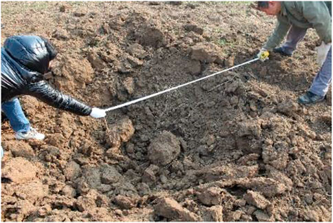
FIGURE 5. Schematic diagram of the field measurements of the main parameters.
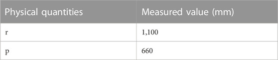
TABLE 1. Crater parameters.
The basic idea of the SPH method is to describe a continuous fluid (or solid) by a group of interacting masses, with each material point carrying various physical quantities, including mass, velocity, etc. By solving the kinetic equations of the mass group and tracking the motion trajectory of each mass, the mechanical behavior of the whole system can be described. By using an interpolation function for the action between each variable mass point in the SPH, the expression can be formulated (Zhang and Fedoroff, 1996), which can be approximated as follows.
where f(x) is a function of the three-dimensional coordinates x, x-x' is the spacing between particles, and h is the smooth length of the particle
Eq. 1 can be transformed into the spatial derivative of the kernel function using the scattering theorem.
Using the particle approximation, Eq. 2 can be summarized by discretization as follows.
where mj is the mass of SPH particle j, ρj is the density of SPH particle j, and N is the number of particles in the smooth length range.
In modeling with the SPH-FEM method, the soil in the near blast zone is discretized based on the SPH method, while the remaining soil is meshed by FEM. The SPH particles and FEM mesh are coupled through the contact algorithm, in which the stress-strain and other information transferred from the SPH particles is passed to the FEM mesh to ensure displacement coordination as a point-plane connection, the principle of which is shown in Figure 6.
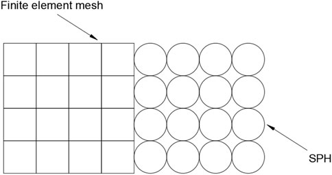
FIGURE 6. Principle diagram of the SPH-FEM.
By analyzing the test parameters and considering the symmetry, ANSYS ADPL was used to define the cell properties and material type and perform the meshing to build a half model. LS-Prepost was used to convert the explosive and the soil in the near area of the explosion into SPH particles and modify the keywords. Since the SPH-FEM method does not need to consider the coupling between air and soil, the air part was not established in the model. To ensure concordance with the test site, the location of the explosives in the model was maintained to be consistent with the real position. ANSYS ADPL was used to define the NODES group, add contact and boundary conditions, ensure the accuracy of the calculation results, and improve the calculation efficiency by setting the appropriate SPH particle density and FEM mesh. The established finite element model is shown in Figure 7.
FIGURE 7. Finite element model.
Based on the actual constraint conditions, the transmittance boundary was selected on both sides and the bottom of the soil cell, and the free boundary is selected on the top. A solid contact was selected between the FEM cell and SPH particles; contact pairs were established using CONTACT_TIED_TO_SURFACE_OFFSET; the symmetry surface was set to the SPH and FEM symmetry boundaries respectively; and DEFINE_BOX was used to control the particle range, boundary, and contact, as defined in Figure 8 in mm-ms-MPa.
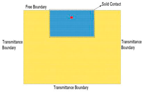
FIGURE 8. Definition of boundaries and contacts.
1) Soil material
The dynamic mechanical response of soils under shallowly buried blast loading was simulated numerically using LS-DYNA software. Using the SOIL_AND_FOAM material model, the ideal plastic yield function is:
where σij is the partial stress component; σ is the average stress; and a0, a1, and a2 are constant terms of the dimensionless J2-σ quadratic fitting curve. The specific calculation parameters of the soil body are shown in Table 2.
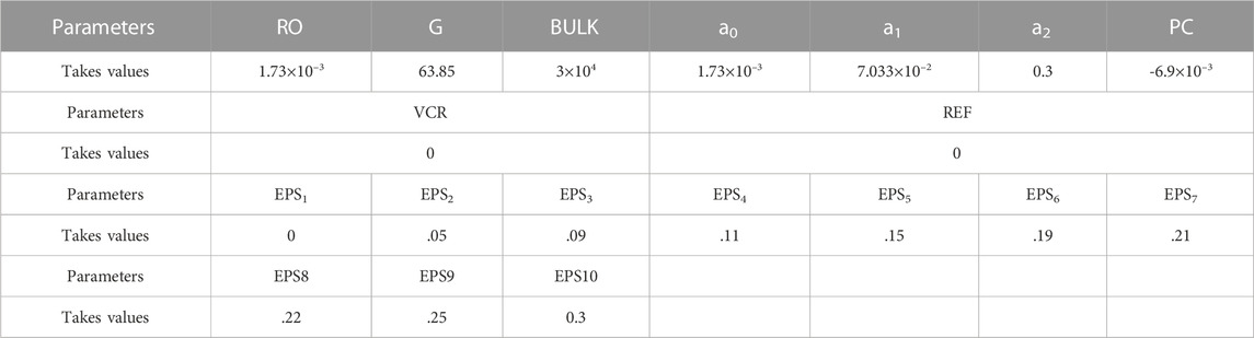
TABLE 2. Soil parameters.
2) Explosives
The *MAT_HIGH_EXPLOSIVE_BURN high-energy explosive combustion model and the JWL equation of state were used to simulate the explosive. The JWL equation of state can be expressed as follows:
where P is the explosion pressure; V is the relative volume of the explosive; E is the initial energy per unit volume of the explosive; and w, A, B, R1, and R2 are material constants. The explosive parameters are shown in Tables 3, 4.

TABLE 3. Explosive material parameters
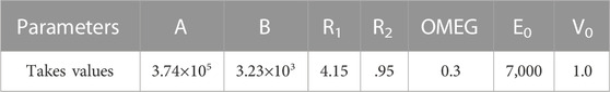
TABLE 4. Equations for the state parameters of the explosive.
To verify the effectiveness of the SPH-FEM method, the experimentally obtained burst crater radius r and visible depth p were calibrated to the simulation results, as shown in Figure 9. The results of the comparison of the numerical simulation and experimental results of these two main parameters are shown in Table 5. Table 5 shows that the relative error of the radius of the burst hole r was 12.4%, the relative error of the visible depth p was 6.36%, and the results did not vary by more than ±15%. The measured size deviation was about 10%. The comparative analysis of the experimental results showed that the numerical simulations of shallowly buried explosions in soil using the SPH-FEM scheme were reasonable and acceptable.
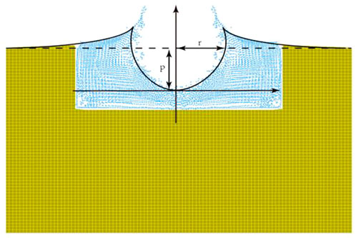
FIGURE 9. Simulation results of the blasting crater.

TABLE 5. Comparisons of numerical simulation and experimental results.
To further verify the effectiveness of the SPH-FEM method, as shown in Figure 10 selected along the depth and distance from the location of the burst core proportional distances of .17, .21, and .31 m/kg1/3 of the three measurement points to extract the time course of the blast shock wave pressure curve in the soil (Figure 11). The test data showed that the propagation of the spherical shock wave and compressional wave generated by the explosion in the soil also obeyed the “explosion similarity law”. Therefore, the maximum pressure Pm of the blast wave at d from the center of the explosion can be obtained according to the volume analysis (Luo et al., 2016). The maximum pressure Pm equation can be expressed as follows:
where Pm is the maximum pressure, ω is the explosives quality, d is the distance to the explosion center and k and α are test constants.
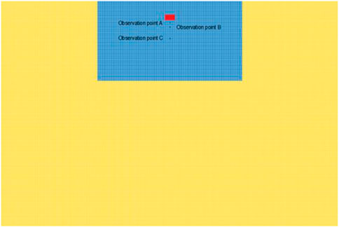
FIGURE 10. Arrangement of measuring points.
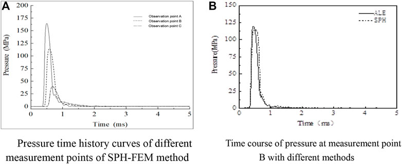
FIGURE 11. Pressure time course curve. (A) Pressure time history curves of different measurement points using the SPH-FEM method. (B) Pressure time course at measurement point B for different methods.
As shown in Figure 11A, with increasing time, the peak pressure of the blast shock wave of each measurement point decayed sharply, finally tending to zero. The blast shock wave pressure of different measurement points also varied. The peak pressure of the blast shock wave decayed sharply with increasing depth and distance. Further comparison of the results from different numerical simulation methods revealed that the peak pressure detected by the SPH-FEM method was 4.6% smaller than that detected by the ALE method for the same measurement point, as shown in Figure 11B. Since the density and looseness of the backfill were also close to the original soil layer after backfilling, the SPH-FEM method was fit for the simulation of explosions in soil. Comprehensive analysis showed that the SPH-FEM method effectively simulated the effect of soil cratering under shallowly buried blast loading.
The pressure of the shock wave from an explosion is another key factor affecting the damage to a target. The shallowly buried explosion caused shock wave propagation in both the air and the soil. The main propagation processes of a shock wave in the soil and air were determined, as shown in Figure 12.
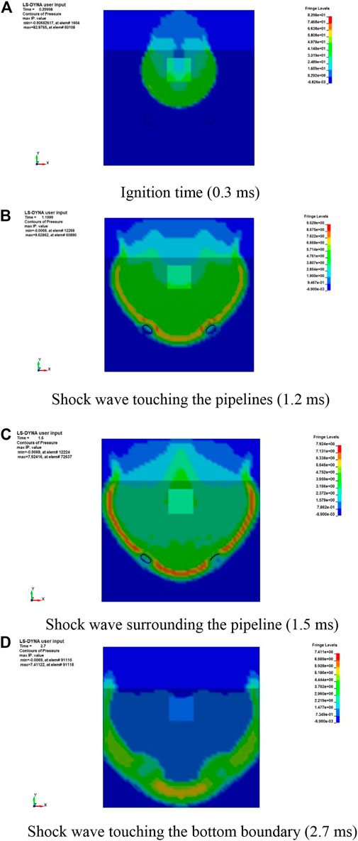
FIGURE 12. Main propagation processes of the shock wave. (A) Ignition time (.3 ms). (B–D) Shock waves touching the pipelines (1.2 ms), surrounding the pipeline (1.5 ms), and touching the bottom boundary (2.7 ms), respectively.
Figures 12A–D show that the pressure values of the shock wave declined rapidly from 82.98 to 7.41 MPa in 2.7 ms. Additionally, the pressure values declined significantly by 88.5% from .3 to 1.2 ms. This meant that the shallowly buried explosion released energy quickly; thus, we focused on the early response of the object. To visualize the shock wave transmission, two pipelines were added to the simulation, as shown in Figures 12B,C. Deformation of the two pipelines was evident, as shown in Figures 12B,C. Furthermore, because the propagation velocity of the shock wave differed between the air and the soil, the shapes of the shock waves also differed, and the projectile effect on the boundary between the air and soil was consistent with the experimental results. Diffraction occurred in the two specimens being surrounded by the shock wave, as shown in Figures 12C,D. All the analysis results showed that the shallowly buried explosion would result in damage to the buried object and the object near the boundary between the air and soil.
The burst crater formation processes simulated by the two methods at different moments are shown in Figure 13. Although both the SPH-FEM and ALE methods simulated the formation process of the burst crater, the same moment based on the SPH-FEM method simulation to obtain the soil deformation was slightly larger than that in the ALE method, while the SPH-FEM method to simulate the height of the soil throw differed from that of the ALE method, likely due to the influence of air and SPH particle mass. Since the SPH is a Lagrangian particle method, in which the calculation of the physical quantities is based on the sum of particles in the cell search domain, and some SPH particles quit working after the explosion, the implementation of boundary conditions in the SPH-FEM method is completely different from the boundary conditions. Although both algorithms can describe the movement and throwing phenomena of the soil after the explosion, the SPH-FEM method clearly represented the peeling phenomenon of the upper soil, while the ALE method was relatively vague. Moreover, the SPH-FEM method effectively avoided problems such as mesh entanglement and distortion and meshed the small deformation region to reduce the computational stress. Therefore, the SPH-FEM method showed more advantages over the ALE method in the simulation of shallowly buried explosions in soil.
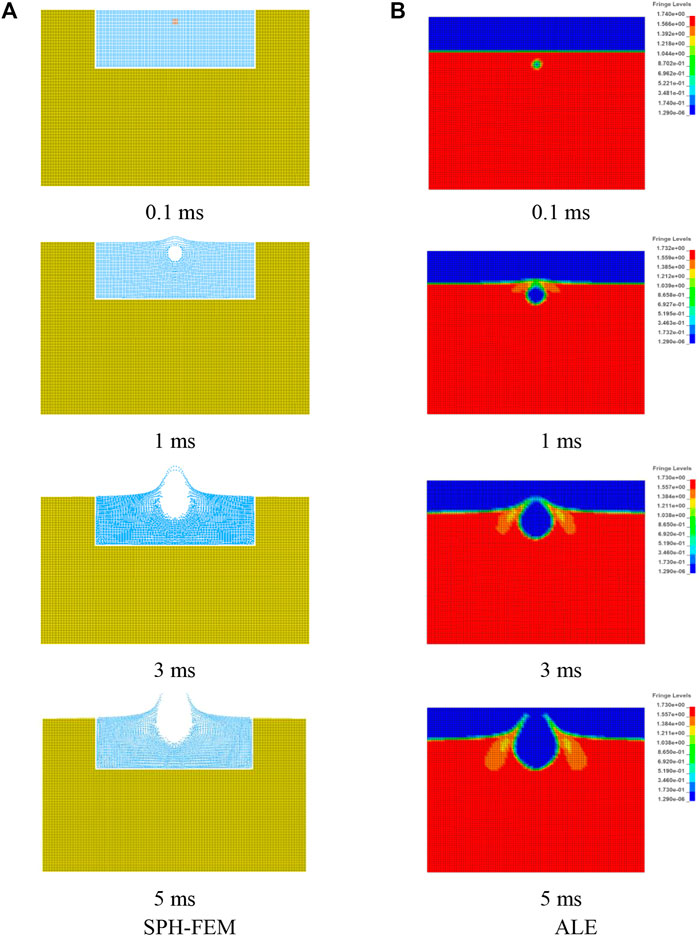
FIGURE 13. Comparisons of the crater formation process between SPH-FEM and ALE. (A) SPH-FEM. (B) ALE.
The cratering effect of shallowly buried explosions in soil was mainly affected by the explosive burial depth and explosive quantity, which are also important parameters for determining the crater size and shape (Ambrosini et al., 2002). Using the SPH-FEM method, the radii of 9.35 kg of TNT explosives at different depths to produce craters were further extracted (Figure 14). Figure 14 demonstrates the trend of increasing crater radius with increasing explosive burial depth in the early stage, which decreased with increasing burial depth after reaching the peak in shallowly buried explosions in the soil. To effectively determine the number of explosives in the correspondence of the crater radius and explosives burial depth, a mathematical fitting method was used to establish the corresponding empirical curve Eq. 7. This empirical curve expressed the relationship between the explosive burial depth d and the radius of the crater r (Figure 14) and determined the relationship between the explosive burial depth and the burst pit radius for 9.35 kg of TNT explosive.
where r is the radius of the burst pit and d is the depth of burial of explosives.
FIGURE 14. Relationship between explosive buried depth and crater radius.
This study designed and implemented a shallow burial static explosion test in soil to determine the parameters of the burst crater. Based on the SPH-FEM and ALE methods, the test data were used to compare the effects of explosive explosion cratering. The conclusions were as follows.
1) Shallowly buried explosions in the soil make a blast funnel and have a particle splash effect. The SPH-FEM method effectively simulated the soil deformation and dispersion effect in this process with a small actual error.
2) The SPH-FEM and ALE methods effectively simulated shallowly buried explosions in soil. Compared to the ALE method, the SPH-FEM method more effectively simulated the shock wave formation of overpressure caused by the deformation of the surrounding soil until the process of breaking.
3) Both SPH-FEM and ALE methods effectively simulated the process of soil explosion cratering. The SPH-FEM method provided a more detailed view of the soil by the explosion load after the peeling phenomenon, with a more efficient calculation.
4) The combination of test data and numerical simulation results with mathematical fitting effectively established a relationship between the explosive burial depth and blast crater radius. The empirical formula established in this study can effectively determine the relationship between the burst crater radius and explosive burial depth of the soil with 9.35 kg of TNT.
The original contributions presented in the study are included in the article/Supplementary Material. Further inquiries can be directed to the corresponding author.
YC, ZL, and JF designed the experiments, defined the intellectual content, performed the literature search, acquired the data, performed data analysis, and prepared the manuscript. JF, ZL, and BZ assisted in the data acquisition, data analysis, and statistical analysis. YC, JF, and ZL performed the literature search, data acquisition, and manuscript editing. YC and ZL performed the manuscript review. All authors have read and approved the content of the manuscript.
This study received funding from the Natural Science Foundation of China (51974255 and 51878056), Natural Science Basic Research Program of Shaanxi Province (2023-JC-YB-296), Key Scientific Research Projects of Shaanxi Provincial Department of Education (22JT035) Postgraduate Innovation, and Practical Ability Cultivation Program of Xi’an Shiyou University (YCS22213121).
The authors declare that the research was conducted in the absence of any commercial or financial relationships that could be construed as a potential conflict of interest.
All claims expressed in this article are solely those of the authors and do not necessarily represent those of their affiliated organizations, or those of the publisher, the editors, and the reviewers. Any product that may be evaluated in this article, or claim that may be made by its manufacturer, is not guaranteed or endorsed by the publisher.
Ambrosini, R. D., Luccioni, B. M., Danesi, R. F., Riera, J. D., and Rocha, M. M. (2002). Size of craters produced by explosive charges on or above the ground surface. Shock Waves 12, 69–78. doi:10.1007/s00193-002-0136-3
Ambrosini, R. D., and Luccioni, B. M. (2019). Effects of underground explosions on soil and structures. Undergr. Space 5, 324–338. doi:10.1016/j.undsp.2019.09.002
Du, X. L., and Lu, D. C. (2011). Advances in soil dynamics and geotechnical earthquake engineering. Rock Soil Mech. 32, 10–20. doi:10.16285/j.rsm.2011.s2.008
Feng, W. T., Xu, C. P., and Li, X. (2020). Calculation and experimental study of pit size. Eng. Blasting 26, 68–72+81. doi:10.3969/j.issn.1006-7051.2020.05.010
Hu, Y. G., Lu, W. B., Chen, M., Yan, P., and Liu, L. (2015). Implementation and verification of SPH-FEM coupling blasting damage analytical method. Chin. J. Rock Mech. Eng. 34, 2740–2748. doi:10.13722/j.cnki.jrme.2014.0104
Jia, Y. S., Wang, W. G., Xie, X. Q., Yang, G., and Yao, Y. K. (2017). Characterization of blast-induced craters in low-moisture and saturated sand from field experiments. Explos. Shock Waves 37, 799–806. doi:10.11883/1001-1455(2017)05-0799-08
Liang, B., Jiang, H. Y., Xu, T. L., Yao, A. L., and Wen, X. (2017). Impact dynamic response of near-field explosion in buried gas pipeline based on SPH-FEM coupling algorithm. Acta Pet. Sin. 38, 1326–1334. doi:10.7623/syxb201711012
Liu, N. F., Li, N., Li, G. F., Song, Z. L., and Wang, S. J. (2022a). Method for evaluating the equivalent thermal conductivity of a freezing rock mass containing systematic fractures. Rock Mech. Rock Eng. 55, 7333–7355. doi:10.1007/s00603-022-03038-9
Liu, Q., Zhai, C. C., Zhang, Y. F., Qu, J. B., and Wu, X. Y. (2022b). Numerical simulation and experimental study of ground impact partitioning in ground and buried explosive soils. Explos. Impact 42, 3–21. doi:10.11883/bzycj-2021-0326
Liu, N. F., Li, N., Wang, S. J., Li, G. F., and Song, Z. P. (2023). A fully coupled thermo-hydro-mechanical model for fractured rock masses in cold regions. Cold Regions Sci. Technol. 205, 103707. doi:10.1016/j.coldregions.2022.103707
Luo, X. B., Zhang, Y. L., and Ding, Y. K. (2016). Explosive mechanics theory course. Arlington Virginia: National Defense Industry Press.
Mu, C. M., Ren, H. Q., Xin, K., and Shi, P. (2010). The effect of explosion in soil under the condition of variable burial depth. J. PLA Univ. Sci. Technol. Nat. Sci. Ed. 11, 112–116. doi:10.7666/j.issn.1009-3443.20100203
Qian, Q. H. (2009). Some advances in rock explosion dynamics. Chin. J. Rock Mech. Eng. 28, 1945–1968. doi:10.3969/j.issn.1000-0844.2007.01.019
Wang, Z. P., Li, H. C., Zhou, S. T., and Li, B. J. (2016). Numerical simulation of cavity volume rule of explosion in loess. Blasting 33, 73–77. doi:10.3963/j.issn.1001-487X.2016.04.013
Xie, D. Y. (2007). Developing situation and problems of soil dynamics in China. Northwest. Seismol. J. 29, 94–95. doi:10.3321/j.issn:1000-6915.2009.10.001
Yue, S. L., Wang, D. R., Fan, P. X., and Wang, M. Y. (2012). “A review of the crater effect of explosions of different scales in rock and soil,” in the conference proceeding of the 3rd national conference on engineering safety and protection, Wuhan, Hubei, 184–190.
Zhang, S. C., and Fedoroff, S. (1996). Neuron microglia interactions in vitro. Chin. J. Comput. Phys. 13, 385–395. doi:10.1007/s004010050440
Zhang, Y. W., Fan, S. Y., Yang, D. H., and Zhou, F. (2022a). Investigation about variation law of frost heave force of seasonal cold region tunnels: A case study. Front. Earth Sci. 9, 806843. doi:10.3389/feart.2021.806843
Zhang, Y. W., Song, Z. P., and Weng, X. L. (2022b). A constitutive model for loess considering the characteristics of structurality and anisotropy. Soil Mech. Found. Eng. 59, 32–43. doi:10.1007/s11204-022-09781-z
Zhao, Z. Y., Zhou, Y. L., Ren, J. W., and Lu, T. J. (2022). Explosion morphology and impact effect of shallow buried explosives. Explos. Impact 42, 52–64. doi:10.11883/bzycj-2021-0376
Keywords: shallow burial explosion, static explosion test, SPH-FEM method, numerical simulation, crater parameter
Citation: Cui Y, Li Z, Fang J and Zhao B (2023) Crater effects of shallow burial explosions in soil based on SPH-FEM analysis. Front. Earth Sci. 10:1114178. doi: 10.3389/feart.2022.1114178
Received: 02 December 2022; Accepted: 28 December 2022;
Published: 12 January 2023.
Edited by:
Naifei Liu, Xi’an University of Architecture and Technology, ChinaCopyright © 2023 Cui, Li, Fang and Zhao. This is an open-access article distributed under the terms of the Creative Commons Attribution License (CC BY). The use, distribution or reproduction in other forums is permitted, provided the original author(s) and the copyright owner(s) are credited and that the original publication in this journal is cited, in accordance with accepted academic practice. No use, distribution or reproduction is permitted which does not comply with these terms.
*Correspondence: Ying Cui, Y3VpeWluZzEyNkAxNjMuY29t
Disclaimer: All claims expressed in this article are solely those of the authors and do not necessarily represent those of their affiliated organizations, or those of the publisher, the editors and the reviewers. Any product that may be evaluated in this article or claim that may be made by its manufacturer is not guaranteed or endorsed by the publisher.
Research integrity at Frontiers
Learn more about the work of our research integrity team to safeguard the quality of each article we publish.