 Wencui Zhang
 Yang Li1*
95% of researchers rate our articles as excellent or good
Learn more about the work of our research integrity team to safeguard the quality of each article we publish.
Find out more
ORIGINAL RESEARCH article
Front. Earth Sci. , 26 January 2023
Sec. Interdisciplinary Climate Studies
Volume 10 - 2022 | https://doi.org/10.3389/feart.2022.1085327
This article is part of the Research Topic Curbing Global Warming with Underground Mine Space for Energy Storage View all 6 articles
China’s traditional connecting aisle construction technology is mainly to combine soil reinforcement with mining excavation. The technology is relatively mature, but it has shortcomings such as long construction period and long-term construction settlement. In order to overcome the above shortcomings, mechanical methods for connecting aisle technology has become increasingly mature after years of research and development, and has been successfully applied in many areas. For the cross-sea tunnel project, this technology was first tried and applied in the interval tunnel of Qingdao Metro Line 8. It is challenging to construct the connecting aisle by mechanical method in Bohai mudstone stratum with high water pressure, which has the construction difficulties such as high excavation requirements, high requirements for post-support function and limited space of main tunnel. In this study, a cutter, propulsion system, and back supporting system were designed to handle the key and difficult points and risks of the aforementioned construction. Furthermore, targeted construction schemes were adopted for sleeve sealing, sleeve removal, and improvement of sleeve sealing. The applicability of the improved mechanical construction method to the geological conditions of the Qingdao area was verified through a numerical simulation. The research results can provide a reference for the mechanical construction of connecting aisle under similar formation conditions.
With the process of urbanization, urban core areas are becoming increasingly congested, and land resources are becoming increasingly scarce. Rail transit construction and underground space development have become important paths to handle urban congestion and to achieve sustainable urban development. In underground engineering, the connecting aisle, as the basic structural unit connecting different underground spaces, underground spaces, and aboveground spaces, plays an extremely important role. Furthermore, the connecting aisle construction is often carried out after the completion of the main space construction, and it can significantly affect the existing structure and environment. The construction methods of connecting aisles can be divided into mechanical and non-mechanical methods according to the mechanization degree of construction excavation. The non-mechanical construction technology mainly adopts mining excavation methods, such as freezing, deep mixing, and high-pressure jet grouting methods, after stratum reinforcement. These construction methods are widely used and are mature technologies, sufficiently covered in the literature. However, they have the following shortcomings: large settlement after freezing and thawing, many factors influencing the construction effect control, and large safety risks. Mechanical connecting aisle construction has low requirements for the main tunnel space, short construction period, and high work efficiency, which meet the engineering development trend and construction requirements. It has been successfully applied in Ningbo, Wuxi, Nanjing, and other places.
Wang (Wang, 2021)took Hangzhou Metro Line 1 as the background and studied the difficulties in the construction of river-crossing shield tunnel project. Shi et al. (Shi et al., 2022) took Xiamen Metro Line 2 as the background, the excavation process of subsea shield tunnel is numerically simulated and the construction mechanical effects in the excavation process are obtained. Liu et al. (Liu et al., 2020) studied the structural response of the main shield tunnel in the mechanical cutting process, and carried out two groups of parallel full-scale experimental studies. The two groups of tests adopted reinforced concrete segments and composite segments respectively, which were placed in the seven-ring vertical test stand. The external water and soil pressure was simulated by 24 external jacks, and the real construction process was simulated by the built-in shield machine and internal support system. The cave-breaking response of the main tunnel was obtained by analyzing the test phenomenon, the internal deformation and internal force of the structure ring, and the deformation between rings. He et al. (He et al., 2019)studied the acceleration response and displacement response of the train load on the main tunnel and the connecting aisle under different connection forms during the construction of the mechanical connecting aisle through the finite element simulation for the joint problem. Ding et al. (Ding et al., 2019)studied the influence of seismic load on the stress, displacement and acceleration response of the main tunnel and the connecting aisle during the construction of mechanical connecting aisle by finite element method. Liu et al. (Liu et al., 2021)studied the influence of mechanical construction of connecting aisle on shield tunnel, based on the shield tunnel of the reconstruction project of Beijing East six Ring Road. Zhang et al. (Zhang et al., 2020)established the discrete element model of connecting aisle excavation of the same size, and studied the surface settlement during shield excavation and the particle coordination number in the soil before the excavation. Many other scholars have also done a lot of work in the field of construction technology and risks of connecting aisle (Pei and Tao, 2011; Pei et al., 2013; Han et al., 2015; Li et al., 2015; Li et al., 2019; Wang et al., 2020a; Wang et al., 2020b; Wu et al., 2020; Yuan et al., 2020; Zhang and Zhong, 2020; Yuan et al., 2021a; Yuan et al., 2021b; Dai and Hu, 2021; Du et al., 2021; Ting et al., 2021; Wang and Meng, 2021; Zhang et al., 2021; Yuan et al., 2022a; Yuan et al., 2022b; Yuan et al., 2022c; Kun et al., 2022; Liu et al., 2022; Pei et al., 2022; Wang et al., 2022; Yang et al., 2022).
Although fruitful research results have been achieved, the research on mechanical methods for connection aisle is relatively less, and even the research of this technology in sea-crossing engineering is rarely reported. The construction of connecting aisles Nos. 9–11 of Qingdao Metro Line eight is the first application of a mechanical method in the construction of offshore mudstone strata in China. During this construction, several column problems such as high water pressure, mudstone penetration, and small space should be solved. On the basis of the analysis of the construction difficulties, this paper summarizes the targeted optimization design of the cutterhead of the mechanical method connecting aisle in the Bohai mudstone stratum with high water pressure. In addition, technical measures to handle problems, such as strengthening of the sealing of the initial sleeve and removal of the sleeve in the construction, are described herein. Furthermore, the composition of the post-supporting system equipment and the key points of the construction technology suitable for this type of stratum are proposed. The applicability of the mechanical method connecting aisle construction in the Bohai mudstone stratum with high water pressure was verified by numerical calculations. The research results provide a reference for similar projects.
Qingdao Metro Line eight starts from Jiaozhou North Station and ends at Wusi Square Station. Its sea-crossing area (Ocean Station-Qingdao North Station) is China’s longest submarine subway tunnel that crosses Jiaozhou Bay. The total length of the line is 7.9 km, and the length of the sea area is 5.4 km. The interval is constructed by the mining and shield methods. An earth pressure shield is used in the land area of the shield method, and a mud shield is used in the sea area. A total of six connecting aisles (Nos. 6–11) were designed in the shield section, of which Nos. 9, 10, and 11 were constructed by a mechanical method. The overall layout of the interval is shown in Figure 1.
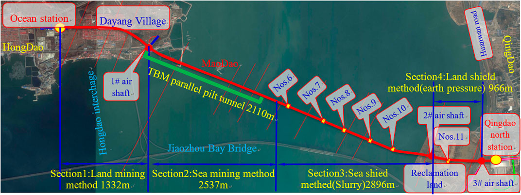
FIGURE 1. Interval general layout.
The main strata through the interval are ⑪silty clay, ⑪1medium coarse sand, ⑫medium coarse sand, ⑫1silty clay, ⑯8-2tuff (sandy cataclastic rock), ⑯11strongly weathered volcanic breccia, ⑯13argillaceous siltstone, ⑰11moderately weathered volcanic breccia, ⑰8-2tuff (sandy cataclastic rock), ⑰13moderately weathered argillaceous siltstone, ⑰11-2moderately weathered volcanic breccia (massive cataclastic rock), ⑱8slightly weathered tuff, and ⑱8-3slightly weathered tuff (joint development zone). The parameters are listed in Table 1. The soil layer through the connecting aisle is basically argillaceous siltstone, as shown in Figure 2.
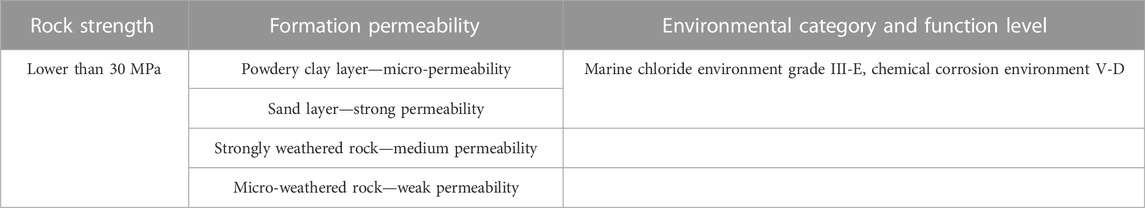
TABLE 1. Rock permeability and environmental categories.
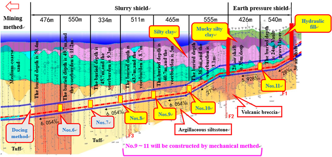
FIGURE 2. Geological profile of the connecting aisle location.
1) Safety construction risk control of high-water-pressure subsea tunnels
With the rapid development of traffic construction and urban construction in China, the construction of river-crossing and sea-crossing shield tunnels has greatly increased, and the engineering scale (diameter and length of tunnels) and water pressure conditions are also increasing. This project is the first application of mechanical connecting aisle construction in a subsea tunnel. The buried depth of the three connecting aisles is large, the maximum buried depth is 37.8 m in the sea area, and the water depth is 41.76 m. The project construction is difficult, which puts forward higher requirements for the deformation and sealing of the excavation machine.
2) Excavation of mudstone strata in the Bohai Sea
Because the shield machine functions as a pressure balance and can maintain the stability of the excavation face, it has been widely used in the construction of urban subways in soft soil layers. At present, several cities with rock strata of subway tunnels (such as Chongqing, Qingdao, and Shenzhen) have adopted shield machine construction, but several problems, such as serious wear of the cutterhead and tool and difficult slag discharge of pipelines, remain. The shield section of the connecting aisle of this project mostly passes through the strata, which easily causes cutterhead and cutter damage. In addition, the propulsion system can greatly influence the engineering excavation.
3) Post-supporting functional requirements and main tunnel space constraints
The construction period of Qingdao Metro Line eight is tight, and the main tunnel space of the mechanical connecting aisle construction is small, which puts forward higher requirements for the function of the supporting system. If the main tunnel is constructed by the shield method, the main propulsion direction is in a straight line with the main tunnel direction, and the trolley can be arranged longitudinally along the tunnel. However, during the construction of the mechanical connecting aisle, the main engine propulsion direction is perpendicular to the main tunnel direction, and the trolley can only be arranged horizontally in the main tunnel. Therefore, the design of the post-supporting system greatly affects the construction development and has a significant influence on the construction period.
In view of the characteristics of the high-water pressure Bohai mudstone stratum in this project, a number of targeted designs and optimizations were proposed for the launching and receiving sleeves, cutterhead system, propulsion system, and post-supporting system of the roadheader.
The joint waterproofing of the tunnel and connecting aisle includes a temporary joint during the construction and a permanent joint after the completion. In the past, the temporary joint of the shield tunnel was mainly composed of a curtain rubber plate and its fastening device, supplemented by circle grouting to block water. However, the machinery of the mechanical connecting aisle construction is introduced from the circular tunnel, where the hole is not a regular circle but a three-dimensional surface, and the conventional hole waterproof device is no longer applicable. Therefore, this project uses a quick-setting inorganic waterproof plugging material as a temporary water stop measure, meeting the type II requirements of the national standard “Inorganic waterproof plugging material (GB23440-2009).” After the connecting aisle is connected, the annular steel plate is used to weld the closed joint, and a water expansion stop is added as an auxiliary waterproof measure.
In view of the characteristics of high water pressure in the tunnel, a 30-mm-thick Q235 steel plate is used for the cylinder material. The longitudinal and circumferential reinforcement plates are welded around each segment of the cylinder to ensure its stiffness. The thickness of the reinforcement plate is 20 mm, the height is 45 mm, and the interval is about 300 × 350 mm. The flange is welded to each joint surface. Specifically, the flange is welded with a 30-mm-thick Q235 plate and is connected to a 10.9 grade M20 bolt. An o-shaped sealing strip is added in the middle. Waterproof structure of a special segment lining joint is show in Figure 3. A schematic of the starting sleeve is shown in Figure 4.

FIGURE 3. Waterproof structure of a special segment lining joint.

FIGURE 4. Starting sleeve schematic.
In view of the excavation of mudstone strata in the Bohai Sea, cutterhead cutting is divided into three stages: 1. Cutting the circular arc glass fiber-reinforced concrete segment at the origin; 2. Cutting the water-bearing silt stratum in the middle section; 3. Cutting the receiving end of the arc glass fiber-reinforced concrete segment. Taking into account the engineering characteristics of the three stages, a modal cutting test of the cutterhead was carried out, and the cutting process was experimentally verified and numerically simulated. The cutterhead design of the mechanical contact tunnel boring machine was optimized. The optimized cutterhead was set as follows: the outer diameter of the cutterhead was 3,290 mm, and the length was 870 mm. The cutterhead was rotated backward. The cutterhead material is Q355B, and the total weight of the structure is 10t. Adopted mechanically driven circular rotary cutterhead. The cutterhead opening rate was optimized to 38%, and the slot width was 200 mm. The conical arc structure was adopted, and the central fishtail cutter was specially designed to facilitate positioning. Two main entrances were configured for residue improvement.
The tool arrangement is shown in Figure 5. It consists of one center fishtail knife, nine hob, twenty-four cutting knives, eight edge scrapers, and twenty-six tearing knives. Two passive mixing rods, three earth pressure sensors, and multiple reserved holes are arranged on the chest. There are four foam injection ports on the face plate of the cutterhead girder, and four active mixing rods are set on the back of the cutterhead girder. The conical structure of four main beams and four auxiliary beams is adopted, and the height distribution of the cutterhead is conical, which is conducive to the shield attitude control in the process of cutting segments. The openings are evenly distributed throughout the disk, and there are sufficient numbers of openings in the central part, which is conducive to the transmission of soil pressure, balance maintenance, and avoidance of the production of mud cake.
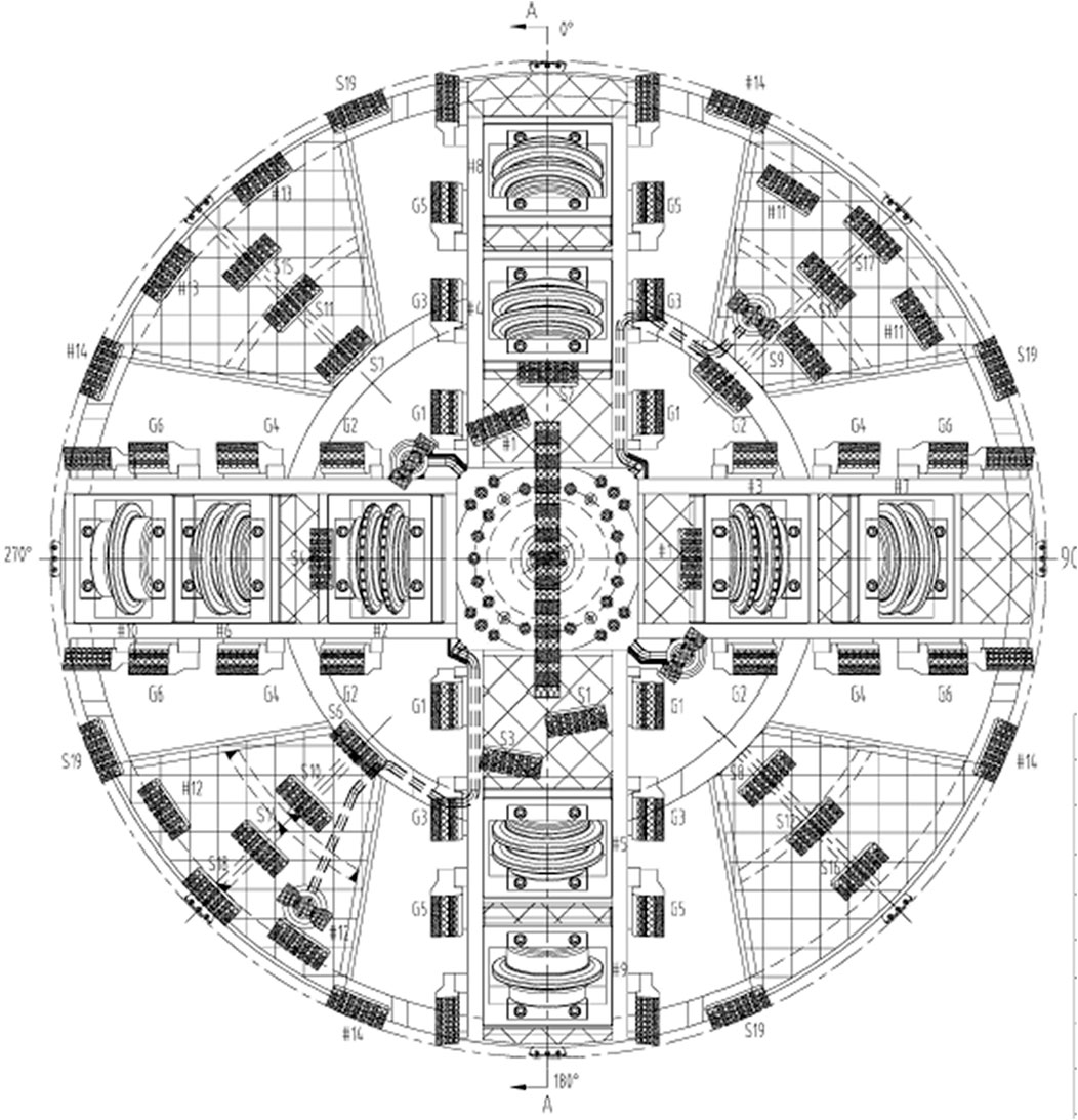
FIGURE 5. Cutter layout.
According to the construction characteristics of the connecting aisle of the mechanical method in the Bohai mudstone stratum, the rock hardness and the water pressure are high in the process of mechanical propulsion. If the propulsion system cannot be reasonably configured, it may lead to insufficient thrust, land subsidence, or uplift. Therefore, the propulsion system is optimized to form a propulsion system suitable for such strata. A total of eight jacks were arranged in this propulsion system, each jack can provide 1,500 kN of force, the maximum thrust is 12,000 kN, and the propulsion stroke is 1,450 mm, as shown in Figure 6.
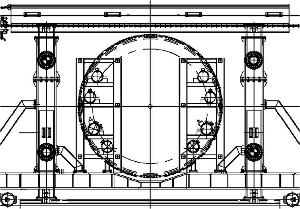
FIGURE 6. Propulsion jack schematic.
The initiation of cutting portal concrete by a pipe jacking machine was estimated.
The total top force can be estimated as
F = F1 + F2 = πD1Lf + 0.25D22R1 =π × 3.26 × 0.9 × 7 + 0.25 × 3.292 × 226 kN = 64.5 kN + 1921.3 kN=1985.8 kN < 4,000 kN, where f is 7 kN/m2. F-total jacking force (kN); F1-Friction resistance between the pipeline and the soil layer (kN), F1 = πD1Lf; D1-Outer diameter of the pipeline (m); L-Pipe jacking length (m); f-Average frictional resistance between the pipe wall and the soil (N/m2), general value: 2–7; F2-Face resistance of the pipe jacking machine (kN), F2 = 0.25 D22R1, D2-Outer diameter of the pipe jacking machine (m); R1-Passive earth pressure at the one-third lower part of the pipe jacking machine (kN/m2).
The calculation and analysis of the deformation were carried out at 4,000 kN. The maximum thrust of the existing equipment propulsion cylinder is 12,000 kN, which can meet the normal propulsion requirements. It can be seen that the optimized propulsion system is reasonable and satisfies the propulsion of the Bohai mudstone formation.
The main tunnel space of the mechanical connecting aisle construction is small, which puts forward higher requirements for the function of the supporting system. Therefore, the entire machine is decomposed into several modules for research and development, and the integrated layout design of electromechanical and hydraulic systems is optimized. The overall equipment diagram of the mechanical connecting aisle is presented in Figure 7.
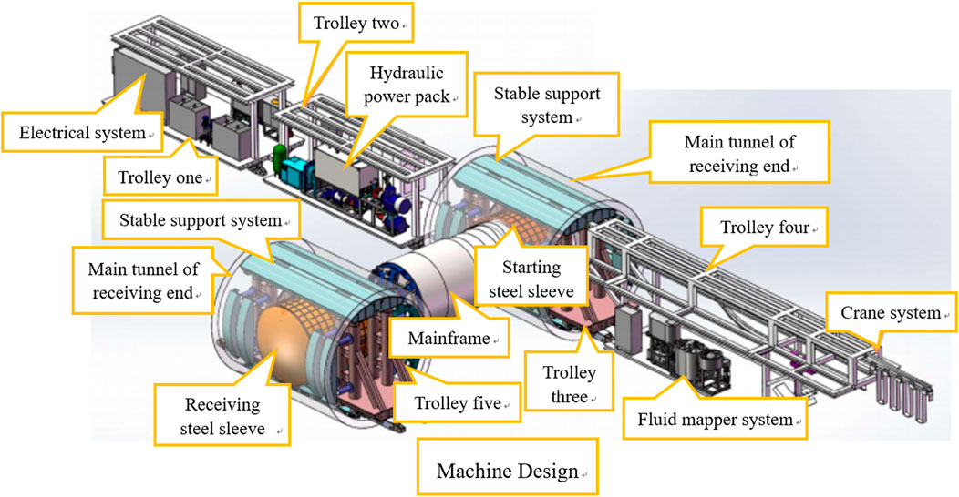
FIGURE 7. Mechanical total equipment diagram.
The five sections of the trailer were assembled by an H-beam and a steel plate as shown in Table 2. The trailer was equipped with electrical, hydraulic, and fluid components and pipelines necessary for the operation of the roadheader. All equipment was arranged on the left and right sides of the trailer. The trailer was designed with an external platform, and personnel walking was safe.
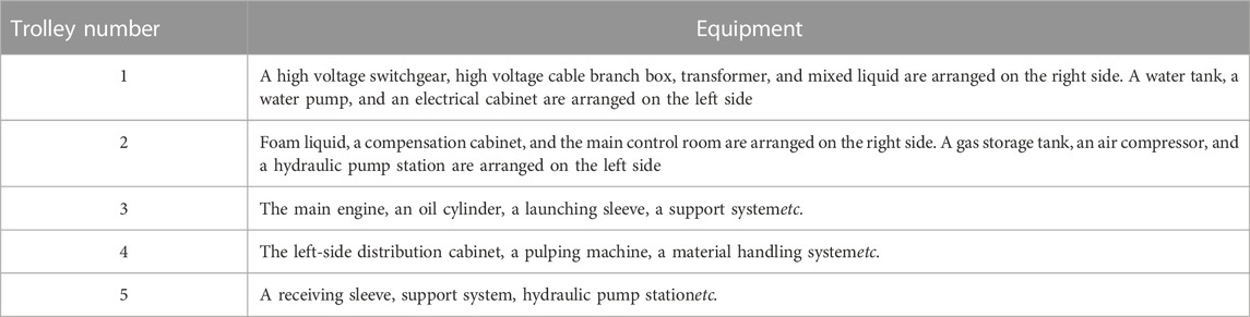
TABLE 2. Comparison table of vehicles and equipment.
The pipe conveying system is composed of a small pipe crane and a curved crane beam, which can realize the pipe transportation and meet the requirements of rapid construction.
In trolley No.3, the main engine, launching sleeve, support, and cylinder were distributed. The reaction structure of the pipe jacking was also on trolley No.3, which was composed of a rear support, cylinder, and negative ring pipe.
In the process of jacking construction, the roadheader extended through the hydraulic cylinder of the main engine. Furthermore, the cylinder support boots were topped to the front ring surface of the negative-ring pipe joint. In this way, the pipe joint moved backward, and the other end ring surface was supported on the back support. After loading, the back support was transferred to the negative-ring pipe joint, to which a reaction force was passed. When the negative-ring pipe joint was still, the main cylinder extension stroke became larger, and the pipe jacking machine was driven forward.
The optimized cutterhead adopts anisotropic panel cutterhead with hob, and the overall design and cutterhead configuration are conducive to shield attitude control and earth pressure transfer and balance during cutting segments, avoid mud cake, and meet the excavation requirements of Bohai mudstone high hydraulic formation. The overall power configuration, main drive torque, thrust and short-distance propulsion of the shield machine propulsion system can meet the requirements of propulsion. The segmented structure assembly adopts the block structure assembly, and the monorail beam transportation system and the assembled jack have strong synergy ability, which can meet the assembly needs and assembly efficiency. The sleeve material is optimized and improved by the steel sleeve method for initiation and reception, and two wire brushes + shield tail grease are used to seal to ensure the temporary sealing of the interface during the launch process, which can ensure the safety of the launch and reception stages. In summary, the optimized equipment can meet the technical requirements of the construction of the connecting aisle in this section.
The steel sleeve method was used for launching and receiving. There was a 65 mm gap between the host and the launching sleeve of the roadheader, and there was an 80 mm gap between the connecting aisle section and the launching sleeve after the host entered the hole. The back end of the launching sleeve was sealed to prevent soil erosion. The used measures were as follows: 1. The sleeve was equipped with three steel brushes, smearing shield tail grease, and filling shield tail grease in the cavity. 2. The back end of the sleeve was assembled on the ground. After welding the tail brush, the shield was smeared with grease, and then, the shield was placed in the sleeve to hoist the whole well. 3. The shield tail oil was intermittently injected into the cavity during tunneling, and the pressure in the cavity was monitored in real time to maintain higher static pressure than the pressure in the sleeve. 4. High-quality polyurethane was prepared as an emergency injection medium.
When the sleeve was removed, if the closure of the portal was not dense, it was prone to soil erosion. The used measures were as follows: 1. A double liquid slurry was injected into the reserved grouting hole at the entrance of the tunnel and the reserved grouting hole of the channel lining to seal the building gap. 2. Before removing the sleeve, it was necessary to open the grouting hole in the position of the steel ring of the portal and to install a stop valve to check the sealing situation. If there was water or mud leakage, the hole was re-grouted until all grouting holes in the first ring of the portal did not exhibit water leakage. 3. When the sleeve was removed, the bolt could not be directly screwed down, and it was confirmed that the door was effectively blocked and removed. 4. In the process of demolition, if leakage occurred, grouting was performed immediately.
Owing to the precise positioning of the launching requirement, the deviation between the launching axis and the steel sleeve installation axis needed to be reduced. The used measures were as follows: 1. The connecting aisle door was measured in advance, and the advanced plan line was calculated. 2. The front posture of the launching sleeve was located according to the axis of the propulsion plan. 3. In the horizontal direction, the installation axis of the steel sleeve was determined according to the axis of the propulsion plan line. In the elevation direction, the installation axis of the steel sleeve was determined according to an elevation of 2‰ on the plan line, and the axis of the steel sleeve was adjusted before the shield was installed into the sleeve.
Cross-sea connecting aisles have high requirements for waterproofing. To ensure sealing, the following measures were taken: 1. A rubber sealing ring and a glass rubber were used to seal the assembly joints of the sleeves. 2. The counter-force cylinder was set along the direction of the sleeve joint. By adjusting the counter-force cylinder, the sleeve joint was always sealed intact. 3. When the deformation of the sleeves was large, strengthening measures were taken immediately, and reinforcing ribs were added at large deformations. 4. After leakage occurred at the bolt joint, the bolt at the joint was tightened immediately. 5. If weld seam leakage occurred during welding reinforcement, it was handled through the pressure relief hole discharge part of the water after welding. 6. The cutter torque and the shield thrust were strictly controlled.
PALXIS 3D software was used to calculate and analyze the stratum deformation caused by the mechanical construction of the connecting aisle. To simplify the calculation and to facilitate modeling, the following assumptions were made: 1. Both rock and soil mass and the lining structure were continuous, homogeneous, and isotropic materials. 2. The construction period of the mechanical connecting aisle was short, so the total stress analysis was carried out according to the undrained condition. 3. The rock and soil remained in close contact with the structure without considering the deformation joints. 4. The initial stress only considered the soil weight and ignored the structural stress. The geological environment of a project was underground engineering in a sensitive environment. The hardening elastic–plastic model was selected considering the plastic and strain hardening characteristics of clay. The model could distinguish between loading and unloading and stiffness depending on the stress level. The soil layer calculation parameters are listed in Table 3.
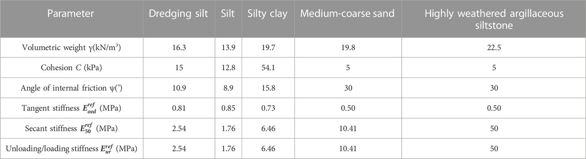
TABLE 3. Calculation parameters of the soil layer.
The simulated size of the model is an area with an east-west length of 100 m and an north-south length of 100m, and the elevation range is 80 m below the surface. Setting horizontal and vertical displacement constrains on the bottom of the model, horizontal displacement constraints of the left and right side of the model, and free boundary on top. As the No.9 and No.10 connecting aisles are located on the seabed, the overlying seawater is simulated by water pressure, and the water severity is taken to 10 kN/m3. The segment structures of the main tunnel and connecting aisle were simulated by using an elastic model and a two-dimensional plate element. The outer diameter of the main tunnel segment was 6,200 mm, the wall thickness was 350 mm, and the ring width was 1.5 m, with C50 concrete. The outer diameter of the connecting aisle segment was 3,260 mm, the wall thickness was 250 mm, and the ring width was 0.9 m C50 concrete was used, and Poisson’s ratio was 0.2. The model was established, as shown in Figure 8.
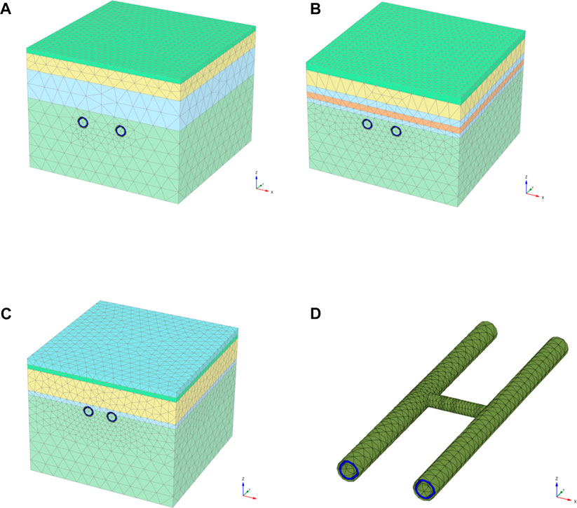
FIGURE 8. 3D finite element model of the connecting aisle. (A) Model of connecting aisle No. 9. (B) Model of connecting aisle No. 10. (C) Model of connecting aisle No. 11 (D) Tunnel structure magnification map of connecting aisle No. 9.
According to the design and construction requirements, the simulation steps completed the mechanical construction process of the connecting aisle. The length of each excavation was 0.9 m, without considering the disturbance of the main tunnel construction on the soil.
The calculation results of the tunnel deformation under the final working condition were analyzed. The vertical and horizontal displacements were ' - ' and’ + ', respectively.
Displacement nephograms of connecting aisles Nos. 9, 10, and 11 are demonstrated in Figures 9–11. It can be seen from the figures that, after the completion of the connecting aisle construction, the maximum horizontal displacements of connecting aisles Nos. 9, 10, and 11 are 1.9 mm, −1.2 mm, and −0.9 mm, respectively. The maximum horizontal displacement is located at the junction of the connecting aisle and the main tunnel. The maximum vertical displacements of connecting aisles Nos. 9, 10, and 11 are −1.0mm, −0.9 mm and −1.1 mm, respectively. The maximum vertical displacement is located at the top of the middle position of the connecting aisle.
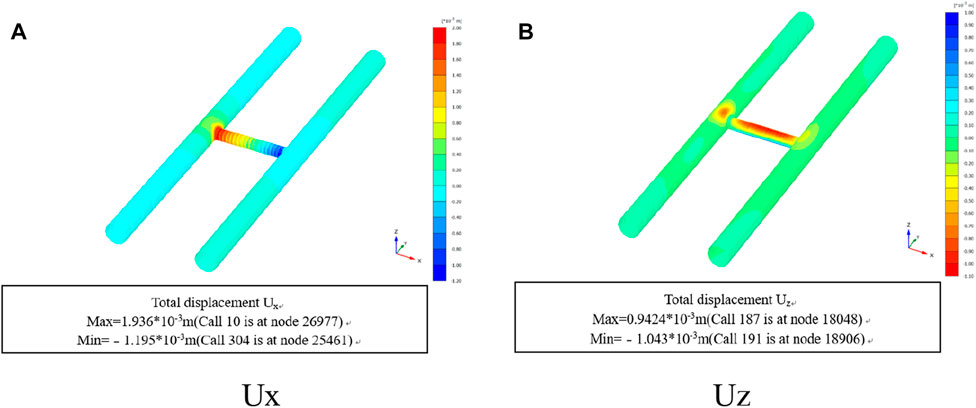
FIGURE 9. (A) UX Displacement nephogram of connecting aisle No. 9. (B) UZ Displacement nephogram of connecting aisle No. 9.
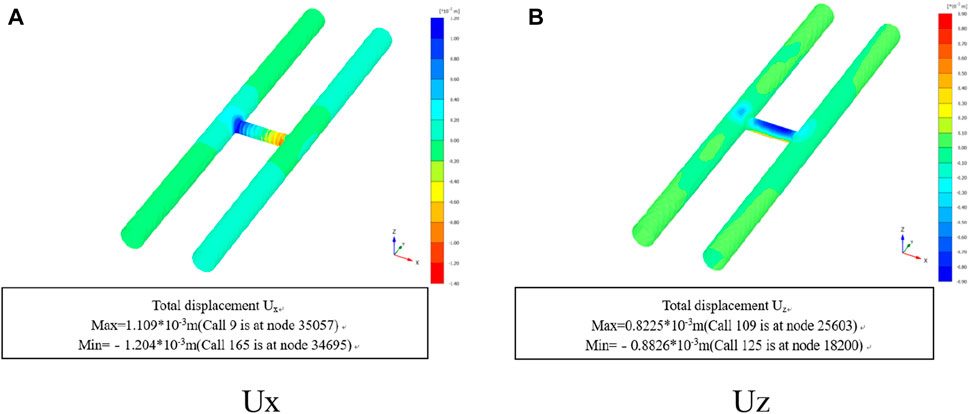
FIGURE 10. (A) UX Displacement nephogram of connecting aisle No. 10. (B) UZ Displacement nephogram of connecting aisle No. 10.
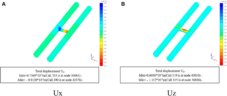
FIGURE 11. (A) UX Displacement nephogram of connecting aisle No. 11. (B) UZ Displacement nephogram of connecting aisle No.11.
The displacement curves of connecting aisles Nos. 9, 10, and 11 under the working conditions are shown in Figures 12–14. As shown in the figures, the maximum horizontal displacement of the connecting aisle increases linearly with the gradual advancement of the connecting aisle. The maximum vertical displacement first increases gradually and then tends to be stable after heading to the middle of the contact tunnel.

FIGURE 12. Displacement curve of connecting aisle No. 9 under the working.
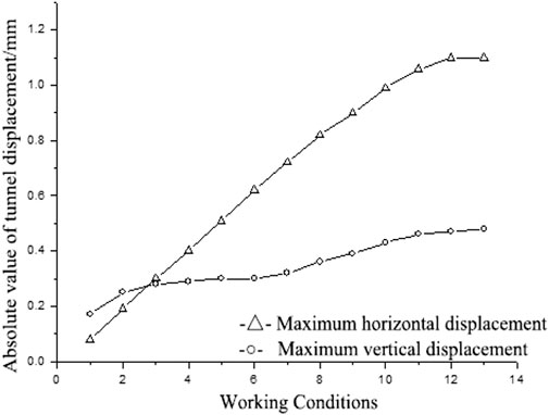
FIGURE 13. Displacement curve of connecting aisle No. 10 under the working conditions.
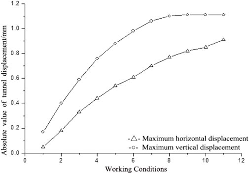
FIGURE 14. Displacement curve of connecting aisle No. 11 under the working conditions.
Soil displacement nephograms for connecting aisles Nos. 9, 10, and 11 are shown in Figures 15–17. It can be seen from the figures that, after the completion of the tunnel construction of the connecting aisle, the maximum vertical displacements of the soil in connecting aisles Nos. 9, 10, and 11 are −0.9mm, −0.8mm, and −1.1 mm, respectively. The maximum value is located at the top of the connecting aisle, and the vertical displacement of the surface soil is close to 0.

FIGURE 15. Vertical displacement nephogram of the soil in connecting aisle No. 9.
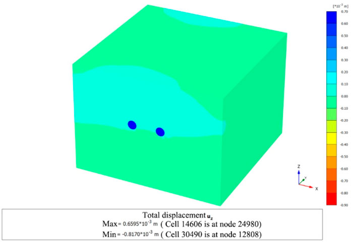
FIGURE 16. Vertical displacement nephogram of the soil in connecting aisle No.10.
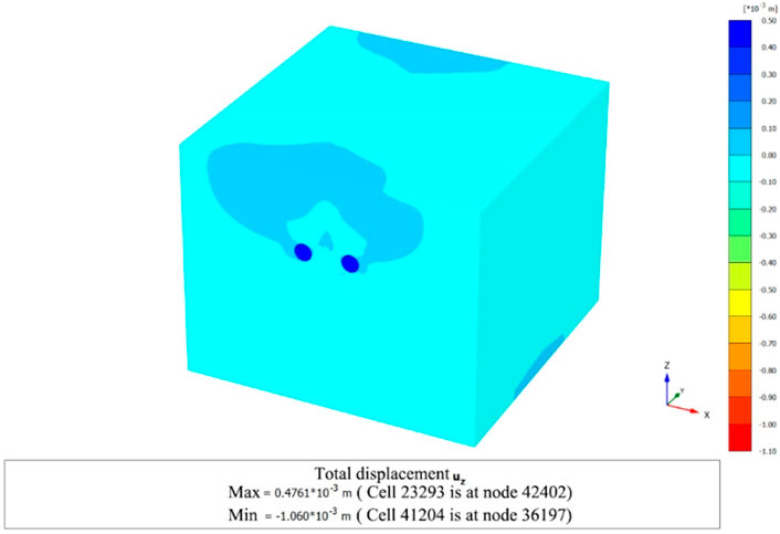
FIGURE 17. Vertical displacement nephogram of the soil in connecting aisle No.11.
The final deformation results are presented in Table 4. The calculation results show that the maximum horizontal displacement of the connecting aisle increases gradually with the tunnel advancement, and the maximum values are located at the junction of the main tunnel and the connecting aisle. The absolute value is greater than that of the vertical displacement. The maximum vertical displacement is a settlement, which first increases and then tends to be stable as the tunnel advances, and the maximum value is located at the top of the middle position of the connecting aisle. After the construction is completed, the maximum vertical displacement of the soil is shown as a settlement. The maximum value is located at the top of the connecting aisle, and the surface vertical displacement is in a controllable range. It can be seen that there will be a certain horizontal displacement at the junction of the main tunnel and the connecting aisle when the connecting aisle is excavated by a mechanical method; therefore, it is necessary to adopt the concrete ring beam structure T-joint for the portal joint. Connecting aisle mechanical excavation has little disturbance to the surrounding soil, and even a sensitive environment can be effectively protected.
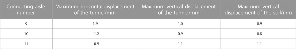
TABLE 4. Summary of the 3D finite element calculation results.
The simulation results listed in Table 4 show that, after a series of studies, such as relevant indoor model tests, equipment selection and optimization, and comprehensive construction technology, the mechanical construction of the connecting aisle can be applied to the seabed and coastal mudstone strata in Qingdao.
1) The optimized cutterhead configuration, cylinder system and support system meet the tunneling requirements in the rock strata below weathering in the Qingdao Metro.
2) Combined with the actual situation of the project, the key and difficult points of the construction were analyzed, such as strengthening the seal at the back end of the original sleeve and soil erosion when the sleeve is removed. The corresponding countermeasures were proposed, and the construction technology of the connecting aisle mechanical method suitable for the geological conditions of the Qingdao area was designed.
3) The numerical simulation results show that a certain horizontal displacement at the junction of the main tunnel and the connecting aisle when the connecting aisle is excavated by a mechanical method. After the construction is completed, the maximum vertical displacement of the soil mass is located at the top of the connecting aisle, and the surface vertical displacement is in a controllable range.
4) Seawater corrosion is a serious challenge for modern offshore engineering. Faced with this problem, it is necessary to continue to strengthen the targeted research of seawater corrosion, further develop and improve equipment performance, and optimize construction technology to meet the application requirements of offshore engineering.
The original contributions presented in the study are included in the article/supplementary material further inquiries can be directed to the corresponding author.
This article was mainly responsible drafting and writing by ZW; LY was responsible for checking and revising the content; DZ was responsible for data processing of numerical simulation, and YQ was responsible for partial data investigation and final content review.
The research is financially supported by the Collaborative Innovation Center of Coastal Urban Rail Transit, Ningbo University (No. XT2021014).
The authors declare that the research was conducted in the absence of any commercial or financial relationships that could be construed as a potential conflict of interest.
All claims expressed in this article are solely those of the authors and do not necessarily represent those of their affiliated organizations, or those of the publisher, the editors and the reviewers. Any product that may be evaluated in this article, or claim that may be made by its manufacturer, is not guaranteed or endorsed by the publisher.
Dai, Z., and Hu, Z. (2021). Upper bound limit analysis of limit support pressure for shield excavation face in composite ground [J]. Adv. Eng. Sci. 53 (02), 95–102. doi:10.15961/j.jsuese.202000008
Ding, X., Wen, Y., Zheng, M., Xiong, Y., and Zhu, Y. (2019). Analysis of seismic load response of communication channel-tunnel system constructed by mechanical method. China Civ. Eng. J. 52 (S2), 193–200.
Du, B., Song, C., He, W., and Li, K. (2021). On transfer technology of D&B construction method at the interface of a subsea tunnel and its application [J]. Mod. Tunn. Technol. 58 (02), 208–213. doi:10.13807/j.cnki.mtt.2021.02.027
Han, L., Xia, X., Wang, J., Ye, G., and Li, Y. (2015). In situ monitoring of frost heave pressure during cross passage construction using ground-freezing method[J]. Can. Geotech. J. 53 (03), 530–539. doi:10.1139/cgj-2014-0486
He, B., Ding, X., Lang, Z., Zheng, M., and Zhu, Y. (2019). Dynamic response of different connection forms of mechanical connection tunnels under train loads [J]. Chin. J. Geotechnical Eng. 41 (S2), 173–176. doi:10.11779/CJGE2019S2044
Kun, F., Xie, H., Xiao, M., et al. (2022). A regional balanced optimal method for segment gasket of shield tunnels [J/OL]. China J. Highw. Transp. 1-11. [2022-01-06]. doi:10.19721/j.cnki.1001-7372.2022.07.015
Li, Z., Kenichi, S., and Wright, P. (2015). Three-dimensional finite element analysis of the behaviour of cross passage between cast-iron tunnels[J]. Can. Geotech. J. 53 (06), 930–945. doi:10.1139/cgj-2015-0273
Li, Z., Ju, L., Li, M., Wang, D., Gong, W., and Li, B. (2019). Study on the construction method of large-section tunnel with water-rich crushing surrounding rock [J]. Mod. Tunn. Technol. 56 (S2), 585–590. doi:10.13807/j.cnki.mtt.2019.s2.084
Liu, X., Gao, Y., Zhang, J., and Zhu, Y. (2020). Structural response of main tunnel linings during construction of connecting aisle by means of mechanized drilling[J]. Chin. J. Geotechnical Eng. 42 (05), 951–960. doi:10.11779/CJGE202005018
Liu, M., Ma, L., Lu, P., Zhang, Z., and Chen, R. (2021). Structural mechanical response impact of cross-passages mechanical construction on super-large diameter shield tunnel. J. Spec. Struct. 38 (05), 106–111. doi:10.19786/j.tzjg.2021.05.022
Liu, Y., Gong, Z., Liang, M., and He, C. (2022). Analysis of mechanical characteristics of shield tunnel with double-layer lining considering variable loads[J/OL]. Railw. Stand. Des. 1-8. [2022-01-06]. doi:10.13238/j.issn.1004-2954.202103060001
Pei, Q., and Tao, X. (2011). Effect of vibration from rail traffic on nearby buildings and its assessment [J]. J. Earthq. Eng. Eng. Vib. 31 (04), 77–83.
Pei, Q., Lei, H., and Liu, H. (2013). Correlation between shear wave velocity and depth of superficial soil layers in Bohai Sea [J]. World Earthq. Eng. 29 (02), 46–51. doi:10.3969/j.issn.1007-6069.2013.02.008
Pei, Q., Wu, C., Cheng, Z., Ding, Y., and Guo, H. (2022). The seismic performance of new self-centering beam-column joints of conventional island main buildings in nuclear power plants. Materials 15 (05), 1704. doi:10.3390/ma15051704
Shi, Y., Wang, C., Zhao, H., et al. (2022). Numerical simulation of subsea shield tunneling process [J/OL]. J. Eng. Geol. 1-11. doi:10.13544/j.cnki.jeg.2021-0165
Ting, H., Zhang, Z., Jiao, L., et al. (2021). Research of advanced support construction technology for water-rich weak surrounding rock bias tunnel [J]. J. Xinyang Normal Univ. Nat. Sci. Ed. 34 (02), 324–330. doi:10.3969/j.issn.1003-0972.2021.02.025
Wang, X., and Meng, Q. (2021). Section design of shield waterproof gasket in underwater shield tunnel [J]. Railw. Stand. Des. 65 (10), 172–178. doi:10.13238/j.issn.1004-2954.202106180009
Wang, J., Zhou, J., Li, F., and Xin, Z. (2020). Study on fluid-solid coupling effect of large diameter underwater shield tunnel excavation [J]. Yangtze River 51 (09), 175–182. doi:10.16232/j.cnki.1001-4179.2020.09.031
Wang, X., Ma, Z., and Zhang, Y. (2020). Research on safety early warning standard of large-scale underground utility tunnel in ground fissure active period. Front. Earth Sci. (Lausanne). 10. doi:10.3389/feart.2022.828477
Wang, X., Song, Q., and Gong, H. (2022). Research on deformation law of deep foundation pit of station in core region of saturated soft loess based on monitoring. Adv. Civ. Eng. 2022, 1–16. doi:10.1155/2022/7848152
Wang, W. (2021). Difficulties analysis and solutions of large section river-crossing tunnel construction in Hangzhou [J]. Urban Mass Transit 24 (03), 134–137+141. doi:10.16037/j.1007-869X.2021.03.031
Wu, P., Li, D., Lu, A., Li, X., and Fu, Y. (2020). Cutter heard and cutter selection of submarine shield tunnel [J]. China Civ. Eng. J. 53 (S1), 162–167+193. doi:10.15951/j.tmgcxb.2020.s1.026
Yang, T., Liu, S., Wang, X., Zhao, H., Liu, Y., and Li, Y. (2022). Analysis of the deformation law of deep and large foundation pits in soft soil areas. Front. Earth Sci. (Lausanne). 10. doi:10.3389/feart.2022.828354
Yuan, D., Wu, J., Shen, X., Jin, D., and Li, X. (2020). Engineering safey of cross-river or cross-sea long-distance large-diameter shield tunneling under super high water pressure[J]. China J. Highw. Transp. 33 (12), 26–45. doi:10.19721/j.cnki.1001-7372.2020.12.003
Yuan, B., Li, Z., Chen, Y., Zhao, Z., Chen, W., Ni, H., et al. (2021). Mechanical and microstructural properties of recycling granite residual soil reinforced with glass fiber and liquid-modified polyvinyl alcohol polymer. Chemosphere 286, 131652. doi:10.1016/j.chemosphere.2021.131652
Yuan, B., Li, Z., Zhao, Z., Ni, H., and Su, Z. (2021). Experimental study of displacement field of layered soils surrounding laterally loaded pile based on transparent soil. J. Soils Sediments 21 (09), 3072–3083. doi:10.1007/s11368-021-03004-y
Yuan, B., Li, Z., Chen, W., Zhao, J., Lv, J., Song, J., et al. (2022). Influence of groundwater depth on pile–soil mechanical properties and fractal characteristics under cyclic loading. Fractal Fract. 6 (4), 198. doi:10.3390/fractalfract6040198
Yuan, B., Chen, M., Chen, W., Luo, Q., and Li, H. (2022). Effect of pile-soil relative stiffness on deformation characteristics of the laterally loaded pile. Adv. Mater. Sci. Eng. 2022, 1–13. doi:10.1155/2022/4913887
Yuan, B., Chen, W., Jin, Z., Yang, F., Luo, Q., and Chen, T. (2022). The effect of organic and inorganic modifiers on the physical properties of granite residual soil. Adv. Mater. Sci. Eng. 2022, 1–13. doi:10.1155/2022/9542258
Zhang, L., and Zhong, X. (2020). Solution of ultimate support pressure on tunnel excavation surface considering cutter plate thickness [J]. J. Henan Univ. Sci. Technol. Nat. Sci. 41 (03), 59–65+7. doi:10.15926/j.cnki.issn1672-6871.2020.03.010
Zhang, Z., Zhang, X., and Wu, F. (2020). Experimental and discrete element analysis on the shield tunneling of a large diameter shallow tunnel in sand [J]. Chin. J. Undergr. Space Eng. 16 (05), 1345–1351+1382.
Keywords: mechanical connecting aisle, high water pressure, equipment design optimization, numerical simulation, construction technology
Citation: Zhang W, Li Y, Dong Z and Yang Q (2023) Construction applicability of mechanical methods for connecting aisle in the bohai mudstone stratum with high water pressure. Front. Earth Sci. 10:1085327. doi: 10.3389/feart.2022.1085327
Received: 31 October 2022; Accepted: 29 November 2022;
Published: 26 January 2023.
Edited by:
Junbao Wang, Xi’an University of Architecture and Technology, ChinaReviewed by:
Liu Jiashun, Liaoning Technical University, ChinaCopyright © 2023 Zhang, Li, Dong and Yang. This is an open-access article distributed under the terms of the Creative Commons Attribution License (CC BY). The use, distribution or reproduction in other forums is permitted, provided the original author(s) and the copyright owner(s) are credited and that the original publication in this journal is cited, in accordance with accepted academic practice. No use, distribution or reproduction is permitted which does not comply with these terms.
*Correspondence: Yang Li, bGl5YW5nQHN0dS5oYXV0LmVkdS5jbg==
Disclaimer: All claims expressed in this article are solely those of the authors and do not necessarily represent those of their affiliated organizations, or those of the publisher, the editors and the reviewers. Any product that may be evaluated in this article or claim that may be made by its manufacturer is not guaranteed or endorsed by the publisher.
Research integrity at Frontiers
Learn more about the work of our research integrity team to safeguard the quality of each article we publish.