 Yulin Ma1*
 Ding Wang
- 1School of Mechanics and Engineering, Liaoning Technical University, Fuxin, China
- 2School of Civil Engineering, Shijiazhuang Tiedao University, Shijiazhuang, China
The presence of bedding planes (BPs) in unconventional shale reservoirs is common and widespread. BPs always affect fracture propagation. The objective of this study was to investigate the impacts of BPs on multiple hydraulic fracturing. The BPs were assumed to be perpendicular to the direction of the fractures. Based on the block distinct element method, we established a numerical model to simulate multiple fracture propagation in reservoirs with BPs. The model considered the fluid partitioning of multiple fractures and the fracture interaction by stress shadow. The numerical simulations clearly showed that the BPs reduced the non-uniform growth of multiple fractures. The results indicated that when hydraulic fractures met BPs, the BPs likely prevented the hydraulic fractures from passing through the formation with a smaller stress contrast. When hydraulic fracturing in a formation containing BPs, the key problem is how to reduce the obstructive effects of the BPs to increase the length of the main fractures.
1 Introduction
Multiple hydraulic fracturing in horizontal wells can increase the complexity of the fracture network after fracturing and can stimulate reservoirs to exploit hydrocarbon in unconventional reservoirs. This is an important guarantee for the commercial exploitation of shale gas. The main methods of multiple-stage fracturing include sequential fracturing, simultaneous fracturing, and alternating fracturing (Roussel and Sharma, 2011). Simultaneous fracturing is a simple and practical method in which the length of each fracture is not uniform. This is because the fracture is affected by the induced stress of adjacent fractures. The issues of multiple fracture propagation mainly include stress interference between fractures, flow partition of each fracture, and fracture propagation competition.
As for the propagation of multiple fractures, the propagation of every fracture is interactional. Every fracture interacts with other fractures by stress interference. Olson (2008) was one of the earliest to conduct a numerical simulation of multi-fracture propagation. Due to mechanical fracture interaction, he discovered that the fractures at the array’s ends had the most freedom to open. Roussel and Sharma (2011) investigated three fracturing sequences for a typical field in the Barnett Shale. The study demonstrated the potential advantages of alternate fracture sequencing and zipper fracs to improve the performance of stimulation treatments in horizontal wells. Peirce and Bunger (2015) confirmed the phenomenon of inner-fracture suppression because of stress shadowing when the perforation clusters were uniformly distributed. Wu and Olson (2015) and Wu and Olson (2016) developed a novel fracture-propagation model. Stress interaction among multiple hydraulic fractures and fluid flow in the single fracture and the horizontal wellbore were integrated into this model. Salimzadeh et al. (2017) applied a fully coupled three-dimensional finite element model to investigate the interaction between multiple simultaneous and sequential hydraulic fractures. Chen et al. (2018) implemented a three-dimensional numerical model to simulate the simultaneous growth of hydraulic fractures in multi-well fracturing. The above-mentioned studies emphasized multiple fracture propagation. In summary, the critical issues for multiple fracture propagation are the stress shadow, the dynamical fluid partition, and the non-uniform growth of multiple hydraulic fractures. Besides, Xie et al. (2020) proposed a new damage constitutive model related to the Weibull distribution and statistical damage theory. The model considers the shear stiffness degradation, post-peak softening, and residual phase of rock joints in the whole shearing process. Li et al. (2018) examined the effect of the erosion of perforation. The results indicated that the erosion significantly deteriorated the non-uniform growth of multiple fractures. Zeng et al. (2018) studied the propagation of multiple hydraulic fractures in an anisotropic formation.
The research methods for multiple fracture propagation include laboratory experiments and numerical simulation. Many explorations have been made using experimental methods to study the various indicators of the rock (Cao et al., 2016; Wang et al., 2020). The principal numerical methods are the Implicit Level Set Algorithm (ILSA) (Dontsov and Peirce, 2017; Peirce and Bunger, 2015), finite element method (FEM) (Salimzadeh et al., 2017), discrete element method (DEM) (Maxwell, 2016; Zhang and Dontsov, 2018; Zheng et al., 2019a; Zhu et al., 2019), discontinuous displacement method (DDM) (Zou et al., 2016a) and phase field method (Wick et al., 2016). Besides, Xu et al. (2017) applied embedded discrete fracture modeling (EDFM) formulation to reservoir simulators with complex geometries. These numerical simulations were mostly 2D and pseudo-3D models (Tang et al., 2019). More recently, three-dimensional models have been built. Kumar and Ghassemi (2018) presented a fully coupled three-dimensional poroelastic analysis of multiple fracture propagation for horizontal wells. Kresse and Weng (2018) believed that the 3D stress shadow affects multistage fracturing in vertical or deviated wells and in multi-well treatments. In the numerical simulation of multiple fracturing, the aforementioned studies conducted a comprehensive study on the mechanism of multiple fracture propagation under simultaneous fracturing.
In unconventional shale reservoirs, the presence of bedding planes (BPs) is common. However, the influence of BPs has not been comprehensively considered yet. Few studies have considered the influence of the BPs on shale reservoirs. Relevant studies have shown that BPs can affect the propagation of fractures. Zheng et al. (2019a) Zheng et al. (2019b) examined the effect of the bedding plane on a single fracture by using the 3DEC software. The results suggested that the fracture propagation behavior was relevant to the intersection angle between the fracture and bedding, and when the bedding was perpendicular to the fractures, the bedding possibly hindered the fracture propagation. Zou et al. (2016b) conducted a series of numerical simulations to illustrate the influence of anisotropy, associated with the presence of BPs, on the geometry of hydraulic fracture network propagation in shale formations. Tan et al. (2017) performed true triaxial hydraulic fracturing experiments using laminated shale outcrops. The study demonstrated that the distance between the injection point and the bedding plane was also a key factor that affected the fracture propagation results. However, when the BPs that exist in the formation are considered, there are few studies on the simultaneous propagation of multiple fractures. Therefore, the objective of this research was to scrutinize the effects of BPs on multiple hydraulic fracturing to fill the gap.
We applied a 3D block distinct element method considering the stress interference and the flow partition of fractures to calculate the multiple fracture propagation in a formation with BPs. In our study, we investigated the effect of BPs on multiple fracture propagation. The role of BPs on fracture propagation is discussed in detail. Our numerical model is a fully 3-dimensional model that can simulate the spatial features, such as lateral propagation of fractures, that two-dimensional models cannot. The numerical simulations of multiple fracturing in a formation with BPs were conducted to study the effect of BPs. The impacts of in-situ stress, the distance from the bedding plane to the wellbore, and bedding number in multi-stage hydraulic fracturing with BPs are discussed in-depth.
2 Numerical model and validation
2.1 The block distinct element method
The numerical modeling has been conducted by the 3D block distinct element method (BDEM) (Cundall, 1988; Hart et al., 1988; Zhang and Dontsov, 2018; Zheng et al., 2019b). In BDEM, the material is modeled using two parts: one part is composed of blocks and the other part is composed of joints. These two parts constitute the discontinuous medium. The deformation characteristics of blocks are described by the stress-displacement relationship. The stress-displacement relationship is expressed as follows:
where
The shear strength of joints is described by the Mohr-Coulomb (M-C) criterion. The contact friction joint model is used in this calculation. This model assumes that the joints have no thickness and that both sides of the blocks are in close contact. One surface is regarded as the target surface, and the other is considered the contact surface. The details of BDEM were introduced and elaborated on in our previous work (Zheng et al., 2019a and Zheng et al., 2019b).
2.2 Validation of the multiple fracturing in the formation without bedding planes
2.2.1 Model description
Some studies (Maxwell, 2016; Zhang and Mack, 2017; Zhang and Dontsov, 2018; Zheng et al., 2019a; Zhu et al., 2019) have used BDEM to simulate hydraulic fracturing. The results of these studies indicated that BDEM could well simulate the propagation of a single fracture and the interaction between hydraulic fracture and natural fracture. Therefore, we did not verify the BDEM simulation for simple crack propagation. We only discussed and verified how to achieve simultaneous fracturing of horizontal wells by BDEM. Studies (see Peirce and Bunger, 2015) have shown that the fracturing fluid pressure in the wellbore is the same regardless of wellbore friction. The pressure boundary is set at the intersection of prefabricated cracks and the wellbore. The pressure is constant in the wellbore. In this way, simultaneous fracturing of multiple fractures can be simulated and flow partition within each fracture can be studied.
The model was established according to Olson (2008). The numerical experiments included only fractures that were initiated from the wellbore, with no natural fractures in the formation. The idealization assumed a horizontal well that provided uniform pressure to seven identical and evenly spaced hydraulic fractures orthogonal to the wellbore trend. The model is shown in Figure 1. Seven prefabricated fracture surfaces (f1–f7) were considered in the formation to simulate seven fractures. The fracture spacing was considered 10 m. The initial fracture size is 20 m. The prefabricated fractures were set as joints. The wellbore was perpendicular to the joints. The horizontal wellbore was located in the middle of the model. The model size of the whole block was 100 m × 50 m × 50 m. The goal of this model was to verify whether BDEM can simulate simultaneous multi-fracture fracturing or not. The existing numerical investigations did not consider the impact of the bedding, thus, the formation model without the bedding was first established. The BDEM was verified by comparison of the model results with those of existing models. To ensure the opening of the crack, the bottom pressure has to be greater than the normal stress of the fracture face. Assume that the buried depth of the formation is 3,000 m, the formation is homogenous and uniform, and the stress is uniform. Therefore, the minimum principal stress is 76.5 MPa. Based on this, the bottom pressure was set to 81 MPa. The values of other parameters are presented in Table 1. The mechanical characteristic parameters were selected based on the true triaxial test results of shale taken from Changning in southern Sichuan, China. The elasticity modulus ranged from 16.6 GPa to 25 GPa. The Poisson’s ratio ranged from 0.17 to 0.32. Thus, the elasticity modulus was set as 20 Gpa, the Poisson’s ratio was set as 0.25, and the density was set as 2,600 kg/m3. The injection fluid was considered water. Therefore, the fluid density was set as 1,000 kg/m3. The fluid viscosity was set as 1.5 cp. The injection rate was set as 0.05 m3/s. This rate is commonly applied in numerical simulation of hydraulic fracturing. Based on the model, the crack propagation and the fluid partition within the fractures were calculated during simultaneous multi-fracture fracturing. The joint model was a weak structural plane and the permeability of the joint was not considered without cracking.
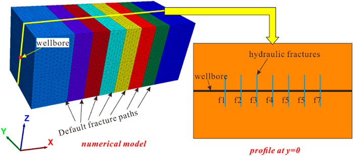
FIGURE 1. Numerical model for multiple hydraulic fractures.
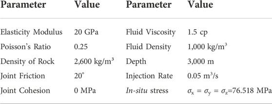
TABLE 1. Values of model parameters.
2.2.2 Validation of results
2.2.1.1 The geometry of seven fractures
The propagation of multiple fractures without considering the bedding is shown in Figure 2. We extracted the preset crack paths separately to show the spatial shapes of the fluid-driven cracks. To avoid the incomplete display of the morphology caused by the overlap between the crack faces, only half of the crack faces were intercepted. The different colors on the crack face indicate the aperture of the crack. The dark blue color indicates that fractures are not cracked (for numerical calculation, the initial crack opening in the model was 1e-4 m), and other colors indicate different crack apertures. The red color exhibits the largest crack aperture.
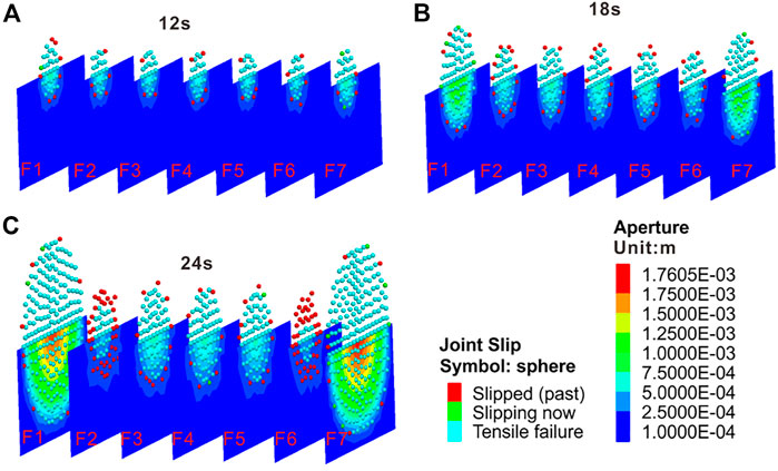
FIGURE 2. Fracture geometry after multiple fracturing. (A-C) the fracture morphology at different times.
At the same time, to show the geometry of the completely fluid-driven crack, the failure point (Joint Slip in Figure 2) was used to represent the spatial geometry of the fractures. The joint slip indicates fracture cracking at this node. In this way, we obtained the spatial shape of the fractures and the distribution of the fracture aperture from Figure 2. Figures 2A–C depicts the fracture morphology at different times. In summary, the slip points show the spatial position of the crack. The different colors on the plane indicate the width of the crack at different spatial locations.
Individual fractures have the shape of a disk (Figure 2). The largest width of fracture is around the intersection of the wellbore and fracture. With the fluid injection, the fracture propagates outward from the center and becomes larger. Of course, the propagation rates of different fractures are affected by the location. In the early stages of fracturing (Figure 2A, 12s), the fracture shape is approximately the same, the fracture length is small, and the interference between the fractures is small. Thus, each fracture expands independently and does not affect the other fractures. As time passes, the exterior fractures of f1 and f7 gradually become dominant fractures, while the internal fractures of f2–f6 are limited by the stress shadow. When the exterior fractures of f1 and f7 propagate to a certain extent (Figure 2C, 24s), they will interfere with the propagation of the neighboring cracks. In Figure 2C, the joint slip is used to analyze whether or not the crack propagates under the current step. It shows that the slip point is red at the edges of the failure regions of the fractures of f2 and f6. The red points mean that no further damage has occurred at this point. This suggests that the two fractures are disturbed by the exterior fractures of f1 and f7 and they fail to propagate outward. The propagation of the exterior crack has suppressed the neighboring fractures of f2 and f6. During simultaneous fracturing, the fractures will interfere with each other, and the exterior fractures are the dominant fractures. The dominant fractures inhibit the propagation of other fractures. The closer the fracture is to the dominant fracture, the greater the impact is.
According to Olson’s (Figure 3A) and Zhao’s (Figure 3B) research, the fractures at the array’s ends have the most freedom to open. The result of BDEM (Figure 3C) is consistent with the results of Olson (2008) and Zhao et al. (2022). This verifies that the calculation method (i.e., the 3D block distinct element method) can simulate multiple fracturing of the horizontal well with great accuracy.
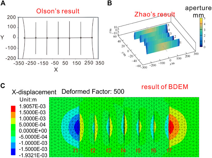
FIGURE 3. Comparison of the model results of simultaneous multi-fracture fracturing with those of Olson (2008) and Zhao et al. (2022). (A) Olson's research; (B) Zhao's research; (C) result of BDEM.
In summary, the exterior cracks of f1 and f7 are dominant cracks. The length and width of the exterior cracks (f1, f7) are larger than those of the inner cracks of f2–f6. Since the fractures propagate vertically, the main displacement of the fracture surface is in the x-direction. Therefore, the contour map of the x-direction displacement was selected to study the change in displacement around the crack. The x-direction displacement on the vertical section (y = 0, where the horizontal well is located) is shown in Figure 3C. The displacement contour map reveals that the exterior cracks of f1 and f7 are dominant cracks. The displacement on both sides of f1 and f7 is the largest and the displacement on both sides of the internal crack is small. It is worth noting that in the exterior crack, the displacement on both sides of the crack is quite different. The absolute value of the left-side displacement of the crack f1 is large, but the absolute value of the displacement on the right side is small. Similarly, the absolute value of the displacement on the right side of the crack f7 is also much larger than that on the left side. Thus, although the exterior crack is a dominant crack, the displacement of the inner side of the crack is small due to the stress interference between the cracks. Olson (2008) concluded that the fractures at the ends of the array had the most freedom to open because they were only opposed by another fracture on one side. The results of this study validated Olson’s conclusions. The displacement of the exterior side plays a major role in the cracking of the exterior crack.
2.2.1.2 The fluid partition within seven fractures
Fluid partition is a critical issue for multiple hydraulic fractures. We calculated the fluid partition by the fluid charging rate at the inlet of every fracture. Figure 4 illustrates the fluid partition of every fracture. The fluid partition at the beginning and end of the experiment is compared first. Figure 4A manifests that there is no significant difference in fluid partition among the seven fractures. The charging rates of f1 and f7 are not the biggest. For the idealized mode, the charging rate of every fracture should be the same. Even though the allocated mesh is not completely uniform, the presence of a non-uniform mesh is not an absolute disadvantage. On the contrary, the non-uniform mesh can better simulate the randomness of rock cracking. Therefore, if the mesh is fine enough, the result is more reflective of the authenticity of the rock fracture. In real conditions, if one fracture opens more easily than another for some reasons, it will be able to take fluid preferentially and grow faster than its neighboring cracks. This case can be simulated by the proposed method.
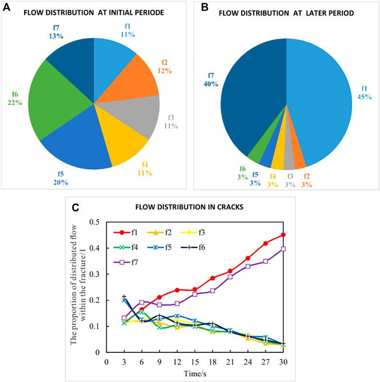
FIGURE 4. Fluid partition in fractures. (A) flow distribution at initial period; (B) flow distribution at later period; (C) flow distribution in cracks.
Figure 4A shows that the partition of f5 and f6 is bigger than the others. They are dominated during the initial period. The differences among the seven fractures are not very great. But at the later stage, fractures f1 and f7 are the dominant fractures. Moreover, the total fluid partition of the dominated fracture is more than 85%. This suggests that the fractures may initiate differently for some reasons, such as initial wellbore or perforation conditions. However, the stress interference among fractures is small because the induced stress of short fractures is not large enough to affect neighboring cracks. Consequently, the dominant fractures in the initial period with small stress interference may be replaced by other fractures with large stress inference in the later period. The initial dominance of the dominated fractures of f5 and f6 is replaced by the later dominance of the exterior fractures of f1 and f7.
Why is the domination of initial dominated fractures replaced? The reason is that in the initial period, the stress interference is small and the fractures are similar. With the increase in fracture length, the interference among fractures becomes larger, and the normal stress on interior fractures of f2–f6 increases. As a result, the propagation of the interior fractures is restrained, and the propagation of the exterior fractures is easier. The real-time fluid partition of seven fractures is plotted in Figure 4C. The curves demonstrate that the partition of f1 and f7 increases and that of others decreases with time. Besides, it is obvious that the fluid partition is consistent with fracture propagation. With the same pore pressure, more fluid flows into the exterior fractures.
2.3 Base case
2.3.1 Model setup
The above section verified the correctness of BDEM predictions in multiple hydraulic fracturing. To study the influence of BPs on the propagation of different fractures, a model considering BPs was established. According to the model described in Figure 1, two horizontal BPs were added above and below the wellbore separately. The BPs were 3 m away from the wellbore. The model is shown in Figure 5. The values of other parameters were consistent with those of Section 2.2.1. There were two assumptions about the BPs. One was that the joint model was a weak structural plane and the permeability of the joint was not considered without cracking. Another one was that the BPs were perpendicular to the direction of the fractures.
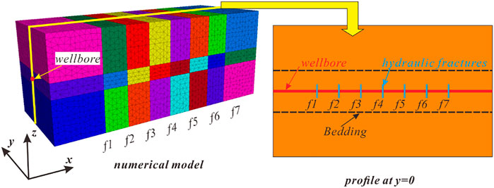
FIGURE 5. The model of multiple hydraulic fracturing considering BPs.
2.3.2 Results for the base case
2.3.1.1 The geometry of seven fractures
We first discuss the effect of the BPs on multiple fracturing. The fracture propagation is shown in Figure 6. This figure suggests that BPs have a significant influence on fracture propagation. Compared to Figure 3C, the fractures in Figure 6 are all restricted except for f7. Furthermore, the fluid-driven crack turns into the BPs. The geometry of f1 and f7 is different. The f7 passes through the BPs directly and propagates vertically. The f7 is still the dominant fracture. While the BPs affect the f1, they do not affect the f7. The vertical propagation of f1 is restricted, and the fluid-driven fracture turns into the BPs.
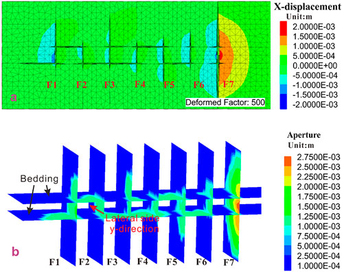
FIGURE 6. Multiple fracture propagation affected by the BPs. (A) 2D schematic view; (B) 3D schematic view.
Figure 6A reveals that the f1 passes through the upper bedding plane but not the bottom bedding plane. The f1 propagates along the bottom bedding plane. The geometry of f1 and f7 is different. The BPs have a significant impact on f1 but no impact on f7. The reason for this prediction by numerical simulation is the presence of the non-uniform grid at the intersections of BPs and two fractures. The difference between f1 and f7 results in different crack initiations, leading to different propagation of f1 and f7. In a real rock mass, the crack initiation is still random. At the intersection of fracture f7 and BPs, the fluid-driven crack breaks through the upper and bottom BPs. Then fracture f7 becomes free from the restriction of BPs. However, the f1 does not break through the bottom bedding plane and propagates along with it. Therefore, the f1 is no longer a dominant fracture. As for the interior fractures of f2-f6, their heights are restricted by the BPs. A 3D schematic view is shown in Figure 6B.
In brief, the BPs may hamper the vertical propagation of fracture. When hydraulic fractures can directly cross the BPs, the BPs have little influence on fracture propagation. In contrast, if the hydraulic fractures cannot directly cross the BPs, the BPs will affect the vertical propagation of the crack.
As for the propagation of the interior fractures, the fractures f2, f4, and f6 are more obviously affected by BPs. The two sides, the upper and bottom sides, are restricted. The f2 is the most obvious example. Because the fractures are hindered by two BPs, they propagate to the lateral sides (y-direction in Figure 6B) and along BPs. It is important to note that the expansion in the y-direction is different from the previous two-dimensional simulation. Previous two-dimensional or pseudo-three-dimensional simulations could not describe the lateral expansion of cracks. Figure 6B shows that the cracks of f1, f2, f4, and f6 have substantial lateral expansion between the two BPs due to the influence of the bedding. Since the lengths of the surrounding cracks of f2, f4, and f6 are small, the cracks of f3 and f5 extend outward at the end of the bedding. Furthermore, the BPs have also become the main channel for crack propagation. In severe cases, the cracks penetrate along the BPs, leading to the connection between the fractures.
Concisely, the BPs will reduce the competition between the wells, and the competitive advantage between the wells is no longer obvious. Moreover, the BPs will impede the vertical extension of the crack. In this case, the length of the main crack of the hydraulic fracturing is limited, and the effect of the reservoir stimulation is greatly reduced. However, in the practice of shale gas development, the bedded shale is often the most effective shale gas producing layer. According to this theory, shale bedding is an unavoidable problem. We can only utilize the relevant processes and techniques to diminish the influence of the BPs on the simultaneous fracture of multiple fractures in horizontal wells.
2.3.1.2 The fluid partition within seven fractures
Similarly, the partition of flow in each crack during multi-fracture fracturing considering the BPs is analyzed. Figure 7A depicts that the interference between the cracks is small at the initial stage of the fracturing, and the cracks do not meet the BPs. At this time, the flow difference between the cracks is small. Figure 7B displays the fluid partition in the later stage of fracturing. The flow rate of crack f7 is the largest, with a ratio of 35%, and the flow rate of the inner cracks of f2-f6 is 9%–11%, which is much larger than the case when there is no bedding plane. This suggests that the bedding plane reduces the competitive advantage between cracks. Besides, although the crack f1 does not become a dominant crack like f7, the flow rate is still larger than the inner cracks. Figure 7C indicates the flow partition of f1 is greater than the other inner cracks during the fracturing process. This suggests that the crack f1 still has a certain propagation advantage. However, the BPs significantly decrease its expansion advantages.
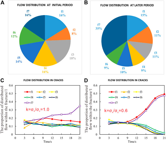
FIGURE 7. Fluid partition in fractures considering the BPs. (A) flow distribution at initial period; (B) flow distribution at later period; (C) flow distribution in cracks when k = 1.0; (D) flow distribution in cracks when k = 0.6.
The uneven fluid distribution in f1 and f7 is because of the minor differences in the grid. The physical reason is the randomness of fracture caused by the structure inside the rock mass in the process of rock fracture. f1 is affected by the BPs during propagation. Thus, it fails to expand outwards. At this condition, f1’s expansion is restricted, and the propagation rate is slowed down, resulting in a reduction in fluid injection rate. However, f7 is not influenced by the BPs, and it can continue to expand, so the amount of liquid is larger than that of f1. The advantages and disadvantages of this heterogeneity will be discussed in Section 4.2. Figure 7D exhibits the fluid partition. Comparing Figures 7C,D (k represents the state of in-situ stress, which will be described in detail in Section 3.1), the results suggest that fracture propagation will become complicated when the stress is uniform. In the case of a larger stress difference, the regularity is stronger. When the stress difference is small, the heterogeneity of the formation is more obvious.
3 Results
3.1 Effect of stress difference
The results of the base case were obtained under uniform in-situ stress conditions. However, the in-situ stress in a real formation is not uniform. To investigate the effect of BPs on multi-fracture fracturing in horizontal wells under different stress conditions, k = σx/σz was defined to represent the state of in-situ stress. σx is the minimum horizontal principal stress of the formation and σz is the vertical in-situ stress of the formation. When k = 1.0, the ground stress is uniform. When k > 1.0, the horizontal stress is greater than the vertical stress, and when k < 1.0, the horizontal stress is smaller than the vertical stress. Other parameters remain unchanged. Initially, k = 0.6 was selected, and the effect of the BPs on crack propagation was observed when the horizontal stress was smaller than the vertical stress. The fracture morphology evolution is shown in Figure 8. The competitive advantage between the cracks was not affected by the BPs under the condition that the vertical stress was greater than the horizontal stress. Similar to the type of fracturing in a non-bedding formation, the stress interference was not significant at the beginning of the fracturing. As the crack expanded, the exterior cracks exhibited a distinct advantage. The inner crack was disturbed by the adjacent crack, and the expansion was suppressed.
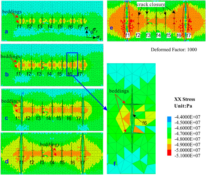
FIGURE 8. The fracture morphology evolution and x stress (k = σx/σz=0.6). (A-E) the fracture morphology at different times.
Although the bedding has little impact on the competition and interference of multiple cracks under this condition, there is a certain amount of cracking at the intersection of the crack and the bedding (Figure 8F). Since the vertical stress on the bedding plane is greater than the horizontal stress on the fracture surface, the crack does not expand along the bedding plane. From the contour plots of Figures 8B–D, the x-direction stress is analyzed, and it can be observed that the stress interference region is more pronounced within the bedding. In Figure 8E, the interference stress of the cracks of f3–f5 is still large in the bedding. The interference stress in other areas is chiefly caused by the external cracks of f1 and f7. The cracks of f2 and f6 are reclosed due to the interference stress caused by the exterior crack.
In summary, under the condition that the vertical stress was greater than the horizontal stress, the bedding had little impact on the multi-fracture competition. The fracture propagation in the formation with or without bedding was similar, that is, the interference between fractures was negligible at the initial stage of fracturing. As the fracturing time increased, the effects between bedding and cracks gradually appeared. Therefore, the shape difference of crack propagation at the initial stage of fracturing was small, and the research had to focus on the later stage of fracturing.
To understand the influence of the bedding plane under different stress states, we chose the fracture morphology at the late stage of k = 0.6/0.8/1.0/1.1. The results are shown in Figure 9. First, by comparing Figures 9A,B, we found the width of the exterior cracks of f1 and f7 was smaller when k = 0.8. This indicates that the horizontal stress limits the width of the crack. In both cases, the fracture shape is consistent, and the vertical expansion advantage of the exterior crack is still obvious. Figure 9C shows the state in which the in-situ stress is uniform and the crack expands in the vertical direction as well as in the bedding direction. The bedding interferes with the vertical expansion of the crack, but it is not completely limited. The results of the horizontal stress greater than the vertical stress (k = 1.1) are exhibited in Figure 9D. At this time, the bedding plane becomes the dominant propagation path, which completely limits the vertical propagation. In short, when k < 1.0, the influence of the bedding plane on simultaneous multi-fracture fracturing is not significant. As the k value increases, the influence of the bedding plane becomes gradually obvious. When k > 1.0, the bedding plane will become the dominant channel, completely limiting the vertical expansion of each crack and eliminating the competitive advantage of expansion between the cracks. Thus, the degree of interference of the bedding plane on multi-crack simultaneous fracturing is related to the state of the in-situ stress.
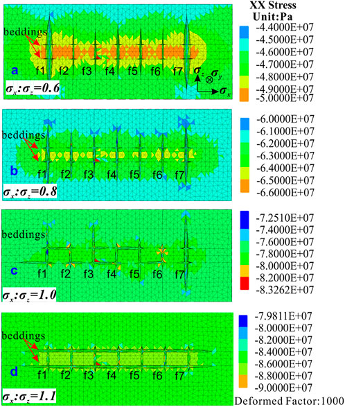
FIGURE 9. Propagation of multiple fractures under different stress states. (A) k = 0.6; (B) k = 0.8; (C) k = 1.0; (D) k = 1.1.
3.2 Effect of distance from the wellbore to the bedding plane
Limiting the vertical expansion of the crack is the main effect of bedding on multi-fracture propagation. The distance from the bedding plane to the horizontal well also affects the fracture shape. We selected the distances of 1 m, 3 m, 6 m, and 9 m for simulation. The distance of 3 m was calculated in the base case. The results for different distances are presented in Figure 10. Figure 10A reveals that the hydraulic crack does not pass through the bedding but expands along the bedding plane when the distance is 1 m. Moreover, the bedding plane between two fractures is almost completely penetrated. Figure 10B shows the result for the 6 m distance. The exterior cracks of f1 and f7 turn into the bedding plane, and the cracks propagate along the bedding plane. The bedding between internal cracks also tends to penetrate through hydraulic cracks, such as the upper bedding plane between f4 and f5. Figure 10C displays the crack propagation pattern when the distance is 9 m. It also exhibits that the exterior cracks of f1 and f7 turn into the bedding. Therefore, the influence of the distance from the wellbore to the bedding on multi-fracture fracturing is very simple. Because of the influence of the bedding, the vertical extension of the crack is limited. Thus, the closer the distance is, the shorter the main crack is.
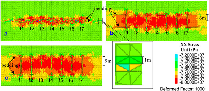
FIGURE 10. Propagation of the fracture with different distances between the BPs and wellbore. (A) distances of 1 m; (B) distances of 6 m; (C) distances of 9 m.
3.3 Effect of the number of bedding planes
In a real formation, there may be multiple BPs. Thus, we examined the effect of the different numbers of BPs on crack propagation. Figure 11 indicates that the number of BPs is sequentially increased on the outer side based on the base case. k = σx/σz was defined as 1.0. The distance between each bedding plane was considered to be 3 m. The cases where the number of the single-sided BPs was from two to four were calculated separately and the results are shown in Figure 12.
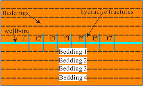
FIGURE 11. Model with multiple BPs.
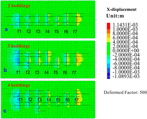
FIGURE 12. Fracture propagation with different numbers of BPs. (A) 2 beddings; (B) 3 beddings; (C) 4 beddings.
Figure 12A depicts crack propagation with two BPs on one side, Figure 12B with three BPs on one side, and Figure 12C with four BPs on one side. In each of these three cases, the crack may extend through the bedding plane while expanding the bedding plane, thereby moving the bedding plane farther from the wellbore. In general, the hydraulic fractures can penetrate bedding one and bedding 2, but bedding three and bedding four have only a few cracks (Figure 13). In the presence of multiple layers, the competitive advantage between cracks is no longer evident. However, as the number of BPs increases, the fracture network after fracturing becomes more complicated. As a result, an increase in the number of BPs will increase the complexity of the fracture network.

FIGURE 13. Fracture propagation in the presence of the seven preset fractures and four BPs.
Only one of the sections of the block is shown in Figure 12C. Thus, the figure cannot characterize the three-dimensional spatial distribution of the crack. Therefore, the seven crack faces and the four bedding faces are shown separately in Figure 13. First, seven cracked faces were analyzed. Blue in the crack face indicates no cracking (set to the initial crack width), and other colors indicate different crack widths. As can be observed from the figure, the lateral expansion (y-direction, left and right for f1–f7, up and down for BPs of 1–4) morphology of the cracks between different BPs is very different. This has a close relationship with the crack connection of the bedding plane. It can be seen from the crack morphology on the bedding surface that the bedding plane between the cracks is penetrated on bedding one and bedding 2. However, only a portion of bedding three and bedding four is cracked. This suggests that the seven cracks can pass through bedding one and bedding 2, but only partially pass through bedding three and bedding 4. Furthermore, the farther the bedding plane is from the wellbore, the more difficult it is to pass through. The crack propagation on the bedding plane makes it easier to see the expansion of the crack face in the lateral direction (i.e., y-direction). Moreover, the expansion in the y-direction will vary depending on the nature of the rock formation. This also indicates that the two-dimensional multi-fracture fracturing simulation can lead to distortion of the analog information. The flow loss caused by the lateral crack propagation is unpredictable in the two-dimensional simulation, and the unevenness of the lateral expansion of the crack leads to a deviation in the results.
4 Discussion
4.1 How to make the fracture network more complex
Section 3.1 indicated that the in-situ stress state determines whether or not the BPs affect multi-crack propagation. When the horizontal stress is much smaller than the vertical stress, the bedding plane has little impact on the crack propagation. In this case, the difference in crack propagation is significant. When the horizontal stress is close to the vertical stress, the BPs will seriously interfere with the expansion of each crack and even thoroughly will limit the vertical expansion of each crack. In the general case, the horizontal stress is considered to be smaller than the vertical stress. However, during the vertical expansion of the crack, the fluid pressure in the crack acts on the crack surface. The pressure on the fracture surface is ultimately transmitted to the formation between the fractures, which leads to an increase in the horizontal stress of the rock mass. In the case where the vertical stress does not change much, the difference between the two decreases. The inhibition of the vertical crack propagation due to the hindering effect of the BPs is becoming more and more obvious.
The distance from a bedding plane to the wellbore primarily affects the length of the main crack. It can be stated that the greater the distance is, the greater the length of the main crack is. Therefore, in actual engineering, horizontal wells should be avoided in two BPs that are too close. When there is a bedding plane near the wellbore, the barrier of the bedding plane should also be reduced in some ways to increase the length of the main fracture. According to the experimental results of related literature (Beugelsdijk et al., 2000; Tan et al., 2017), it is believed that the increase in the injection rate and viscosity of the fracturing fluid can effectively increase the length of the main crack. Then the length of the main crack should be increased by performing some processes in the formation where the bedding is present.
Under the condition that the length of the main crack can be guaranteed, the BPs are conducive to the complexity of the fracture networks. It is clear that the increase in the number of BPs increases the complexity of the crack. Consequently, the influence of bedding on multi-fracture fracturing should be addressed controversially. On the one hand, the presence of bedding affects the vertical extension of the fracture and reduces the length of the main fracture. In this respect, the bedding is not conducive to fracturing. On the other hand, bedding connectivity can increase crack complexity. In cases where the length of the main crack can be ensured, the bedding is advantageous for well stimulation by hydraulic fracturing. As a result, the influence of bedding on well stimulation by hydraulic fracturing should be discussed according to the current situation. It is not logical to state confidently that the bedding is beneficial or not conducive to fracturing.
In short, to obtain a more complex fracture network in a formation with multiple BPs, there are two key points: the length of the main fractures and crack propagation in the BPs. However, the two are contradictory. First, the length of the main fracture should be obtained. This is a question about how cracks pass through more BPs. According to Section 3.1, in-situ stress may affect fracture propagation. Relevant studies (Li et al., 2017; Manríquez, 2018) have demonstrated that the in-situ stress can be changed by neighboring fractures or wells. Thus, stress intervention is a method to control in-situ stress. Then a longer main fracture may be obtained. Laboratory experiments (Beugelsdijk et al., 2000; Tan et al., 2017) showed that a larger injection rate and fluid viscosity were conducive to the propagation of the main fracture in formations with bedding. Furthermore, the approach angle between the fracture and the bedding plane also affects the propagation behavior. The study of Zheng et al. (2019b) indicated that a longer main fracture may form at a higher approach angle if the cementation of BPs is not weak. On the contrary, for fracture propagation in BPs, stress intervention, smaller injection rate, and smaller fluid viscosity are useful in general. The recommended road map for a complex network is to first acquire the long main fractures and then allow the fractures to expand within the BPs.
4.2 Grid meshing
In the real world, the rock mass is heterogeneous. Therefore, crack propagation has certain randomness (see Figure 6). A slight difference in the initial state of the crack results in a significant difference in the final shape of the crack. The slight difference in the meshing of the rock mass is not considered a critical shortcoming for the simulation. Instead, it can reflect the heterogeneity of rock mass. Through the slight difference in the meshing, we realized that under almost the same stress conditions, the shape of the crack would also be greatly different. Although the grid difference causes a difference in cracking, the damage discrimination mode used in the simulation is the same. Therefore, grid meshing is not a very critical issue.
Although the meshing difference can reflect the heterogeneity of rock mass, there are still some issues related to meshing that need further discussion. All we know is that the difference in the mesh causes the difference in the fracture initiation. The differences in the mesh which lead to the differences in the fracture initiation and the properties which these grid differences represent in the rocks remain unclear. Thus, they need to be studied in more detail.
For capturing the heterogeneity of rock mass, we should ensure the regular accuracy of the simulated results. We have already discussed the mesh dependency of the simulation results in our previous work (Zheng et al., 2019b). The size of the mesh is determined by the edge. Therefore, the edge lengths were selected as 0.5 m, 1.0 m, and 2.0 m for examining mesh dependency. The results showed that with the increase in mesh size, the fluctuation in the simulation outcomes was more obvious. In sum, the mesh should be small enough to ensure accurate results. However, to characterize the heterogeneity of the rock mass, the mesh must not be too small. To satisfy these two points, the edge size was considered 1.0 m. According to our previous work (Zheng et al., 2019b), the edge size of 2.0 m can ensure accurate results.
4.3 From two-dimensional analysis to three-dimensional analysis
In this study, we analyzed the three-dimensional shape of the crack. The two-dimensional or quasi-three-dimensional analysis of crack propagation is performed only at a certain plane, and the height of the crack is assumed to be constant. Crack propagation under two-dimensional conditions is shown in Figure 14. When the hydraulic crack propagates to the joint surface, the crack can only continue to expand in one or two directions, and the other directions are ignored in the 2D calculations. But for three-dimensional propagation, the expansion direction of the crack has one more choice. The crack can be expanded in direction 3, which is called lateral expansion. The three-dimensional calculations suggest that the lateral expansion of the crack faces at different positions is not the same, and the height of the crack in the space is not the same too. Figure 13 indicates that the difference in crack height is very large. Under these conditions, the advantages of 3D analysis are well reflected. The three-dimensional hydraulic fracturing model can better represent the shape of hydraulic fractures more realistically.
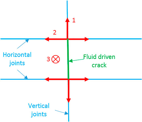
FIGURE 14. Schematic diagram of crack propagation direction.
We simulated the expansion of cracks on a three-dimensional scale. However, the crack was preset during the simulation. This situation did not take into account the deflection of the crack under stress interference. The numerical simulation method for the three-dimensional expansion of hydraulic fracturing remains to be developed. Although the relevant literature has simulated three-dimensional hydraulic fracturing, most of them are still simplified or need to meet special requirements. From the current literature, BDEM is one of the most effective methods for simulating three-dimensional hydraulic fracturing. Simulations for 3D hydraulic fracturing are expected to be simpler, more efficient, and more realistic.
5 Conclusion
1. When multiple cracks are simultaneously fractured, the expansion priority between the cracks is different due to stress interference between the cracks. The exterior crack has a greater vertical expansion compared to the inner crack. The internal crack is disturbed by the stress between the cracks, and the crack propagation is limited. Under high-stress conditions, internal cracks may close after cracking. Besides, the flow distribution of the crack is the same as the expansion of the crack.
2. The presence of the bedding plane will hinder the vertical expansion of the crack. The bedding plane reduces the difference in expansion between cracks. The smaller the stress difference, the more obvious the effect of the bedding plane. When the stress difference is large, the effect of the bedding plane on the crack advantage is not obvious.
3. The effect of the bedding plane on fracturing should be evaluated from two perspectives. On the one hand, the bedding plane impedes the vertical expansion of the crack and reduces the length of the crack. This will reduce the range of the well stimulation by hydraulic fracturing. This is not conducive to the hydraulic fracturing of the reservoir. On the other hand, the bedding plane increases the complexity of the fracture network after fracturing. This is beneficial for reservoir fracturing. Therefore, in the fracturing process of layered formations, the key issue is how to reduce the limitation of the length of the main cracks so that the cracks extend farther. This allows for a greater range of well stimulation by hydraulic fracturing.
4. The recommended workflow for a complex network is to first obtain the long main fractures and then allow the fractures to expand within the bedding plane. Stress intervention, the change of the injection rate and fluid viscosity, and adjustment of the approach angle between fracture and bedding plane can be applied to attain a more complex fracture network.
Data availability statement
The original contributions presented in the study are included in the article/Supplementary Material, further inquiries can be directed to the corresponding author.
Author contributions
YM completed the simulation and manuscript. DW helped on the manuscript and YZ helped on the simulation.
Funding
This research was funded by the China National Science and Technology Major Project (Grant No. 2017ZX05037001), the Liaoning Province Applied Basic Research Program (2022JH2/101300136), and by the Discipline Innovation Team Project of Liaoning Technical University (Grant No. LNTU20TD-11).
Acknowledgments
We would like to thank Liuke Huang, a visiting scholar at Tongji University, for his help in applying the block distinct element method. Besides, we are grateful to the International Science Editing (http://www.internationalscienceediting.com) for editing this manuscript.
Conflict of interest
The authors declare that the research was conducted in the absence of any commercial or financial relationships that could be construed as a potential conflict of interest.
Publisher’s note
All claims expressed in this article are solely those of the authors and do not necessarily represent those of their affiliated organizations, or those of the publisher, the editors and the reviewers. Any product that may be evaluated in this article, or claim that may be made by its manufacturer, is not guaranteed or endorsed by the publisher.
References
Beugelsdijk, L. J. L., de Pater, C. J., and Sato, K. (2000). “Experimental hydraulic fracture propagation in a multi-fractured medium,” in SPE asia pacific conference on integrated modelling for asset management (Yokohama, Japan: Society of Petroleum Engineers), 8.
Cao, R., Cao, P., Fan, X., Xiong, X., and Lin, H. (2016). An experimental and numerical study on mechanical behavior of ubiquitous-joint brittle rock-like specimens under uniaxial compression. Rock Mech. Rock Eng. 49 (11), 4319–4338. doi:10.1007/s00603-016-1029-6
Chen, X., Li, Y., Zhao, J., Xu, W., and Fu, D. (2018). Numerical investigation for simultaneous growth of hydraulic fractures in multiple horizontal wells. J. Nat. Gas Sci. Eng. 51, 44–52. doi:10.1016/j.jngse.2017.12.014
Cundall, P. A. (1988). Formulation of a three-dimensional distinct element model—Part I. A scheme to detect and represent contacts in a system composed of many polyhedral blocks. Int. J. Rock Mech. Min. Sci. Geomechanics Abstr. 25 (3), 107–116. doi:10.1016/0148-9062(88)92293-0
Dontsov, E. V., and Peirce, A. P. (2017). A multiscale implicit level set algorithm (ILSA) to model hydraulic fracture propagation incorporating combined viscous, toughness, and leak-off asymptotics. Comput. Methods Appl. Mech. Eng. 313, 53–84. doi:10.1016/j.cma.2016.09.017
Hart, R., Cundall, P. A., and Lemos, J. (1988). Formulation of a three-dimensional distinct element model—Part II. Mechanical calculations for motion and interaction of a system composed of many polyhedral blocks. Int. J. Rock Mech. Min. Sci. Geomechanics Abstr. 25 (3), 117–125. doi:10.1016/0148-9062(88)92294-2
Kresse, O., and Weng, X. (2018). Numerical modeling of 3D hydraulic fractures interaction in complex naturally fractured formations. Rock Mech. Rock Eng. 12, 3863–3881. doi:10.1007/s00603-018-1539-5
Kumar, D., and Ghassemi, A. (2018). Three-dimensional poroelastic modeling of multiple hydraulic fracture propagation from horizontal wells. Int. J. Rock Mech. Min. Sci. 105, 192–209. doi:10.1016/j.ijrmms.2018.01.010
Li, X., Wang, J., and Elsworth, D. (2017). Stress redistribution and fracture propagation during restimulation of gas shale reservoirs. J. Petroleum Sci. Eng. 154, 150–160. doi:10.1016/j.petrol.2017.04.027
Li, Y., Chen, X., Zhao, J., Xu, W., Wu, J., and Fu, D. (2018). Influence of perforation erosion on multiple growing hydraulic fractures in multi-stage fracturing. Nat. Gas. Ind. B 5 (1), 8–15. doi:10.1016/j.ngib.2017.11.002
Manríquez, A. L. (2018). Stress behavior in the near fracture region between adjacent horizontal wells during multistage fracturing using a coupled stress-displacement to hydraulic diffusivity model. J. Petroleum Sci. Eng. 162, 822–834. doi:10.1016/j.petrol.2017.11.009
Maxwell, S. C. L. B. (2016). “Calibrated microseismic geomechanical modeling of a horn river basin hydraulic fracture,” in The 50th US Rock Mechanics/Geomechanics Symposium.
Olson, J. E. (2008). “Multi-fracture propagation modeling: Applications to hydraulic fracturing in shales and tight gas sands,” in The 42nd US rock mechanics symposium (USRMS), San Francisco.
Peirce, A., and Bunger, A. (2015). Interference fracturing: nonuniform distributions of perforation clusters that promote simultaneous growth of multiple hydraulic fractures. SPE J. 20 (02), 384–395. doi:10.2118/172500-pa
Roussel, N. P., and Sharma, M. M. (2011). Optimizing fracture spacing and sequencing in horizontal-well fracturing. SPE Prod. Operations 26 (02), 173–184. doi:10.2118/127986-pa
Salimzadeh, S., Usui, T., Paluszny, A., and Zimmerman, R. W. (2017). Finite element simulations of interactions between multiple hydraulic fractures in a poroelastic rock. Int. J. Rock Mech. Min. Sci. 99, 9–20. doi:10.1016/j.ijrmms.2017.09.001
Tan, P., Jin, Y., Han, K., Hou, B., Chen, M., Guo, X., et al. (2017). Analysis of hydraulic fracture initiation and vertical propagation behavior in laminated shale formation. Fuel 206, 482–493. doi:10.1016/j.fuel.2017.05.033
Tang, H., Wang, S., Zhang, R., Li, S., Zhang, L., and Wu, Y. S. (2019). Analysis of stress interference among multiple hydraulic fractures using a fully three-dimensional displacement discontinuity method. J. Petroleum Sci. Eng. 179, 378–393. doi:10.1016/j.petrol.2019.04.050
Wang, Y., ZhangLin, H. H., Zhao, Y., and Liu, Y. (2020). Fracture behaviour of central-flawed rock plate under uniaxial compression. Theor. Appl. Fract. Mech. 106, 102503. doi:10.1016/j.tafmec.2020.102503
Wick, T., Singh, G., and Wheeler, M. F. (2016). Fluid-filled fracture propagation with a phase-field approach and coupling to a reservoir simulator. SPE J. 21 (03), 0981–0999. doi:10.2118/168597-pa
Wu, K., and Olson, J. E. (2016). Mechanisms of simultaneous hydraulic-fracture propagation from multiple perforation clusters in horizontal wells. SPE J. 21 (031), 1000–1008. doi:10.2118/178925-pa
Wu, K., and Olson, J. E. (2015). Simultaneous multifracture treatments: fully coupled fluid flow and fracture mechanics for horizontal wells. SPE J. 20 (02), 337–346. doi:10.2118/167626-pa
Xie, S., Lin, H., Wang, Y., Chen, Y., Du, S., Zhao, Y., et al. (2020). A statistical damage constitutive model considering whole joint shear deformation. Int. J. Damage Mech. 4, 988–1008. doi:10.1177/1056789519900778
Xu, Y., Cavalcante Filho, J. S., Yu, W., and Sepehrnoori, K. (2017). Discrete-fracture modeling of complex hydraulic-fracture geometries in reservoir simulators. SPE Reserv. Eval. Eng. 20 (02), 403–422. doi:10.2118/183647-pa
Zeng, Q., Liu, W., and Yao, J. (2018). Numerical modeling of multiple fractures propagation in anisotropic formation. J. Nat. Gas Sci. Eng. 53, 337–346. doi:10.1016/j.jngse.2018.02.035
Zhang, F., and Dontsov, E. (2018). Modeling hydraulic fracture propagation and proppant transport in a two-layer formation with stress drop. Eng. Fract. Mech. 199, 705–720. doi:10.1016/j.engfracmech.2018.07.008
Zhang, F., and Mack, M. (2017). Integrating fully coupled geomechanical modeling with microsesmicity for the analysis of refracturing treatment. J. Nat. Gas Sci. Eng. 46, 16–25. doi:10.1016/j.jngse.2017.07.008
Zhao, W., Ji, G., Li, K., Liu, W., Xiong, L., and Xiao, J. (2022). A new pseudo 3D hydraulic fracture propagation model for sandstone reservoirs considering fracture penetrating height. Eng. Fract. Mech. 264, 108358. doi:10.1016/j.engfracmech.2022.108358
Zheng, Y., Liu, J., and Zhang, B. (2019b). An investigation into the effects of weak interfaces on fracture height containment in hydraulic fracturing. Energies 12 (17), 3245. doi:10.3390/en12173245
Zheng, Y., Liu, J., and Lei, Y. (2019a). The propagation behavior of hydraulic fracture in rock mass with cemented joints. Geofluids 15, 1–15. doi:10.1155/2019/5406870
Zhu, H., Shen, J., and Zhang, F. (2019). A fracture conductivity model for channel fracturing and its implementation with Discrete Element Method. J. Petroleum Sci. Eng. 172, 149–161. doi:10.1016/j.petrol.2018.09.054
Zou, Y., Ma, X., Zhang, S., Tong, Z., and Han, L. (2016a). Numerical investigation into the influence of bedding plane on hydraulic fracture network propagation in shale formations. Rock Mech. Rock Eng. 9, 3597–3614. doi:10.1007/s00603-016-1001-5
Keywords: hydraulic fracturing, multiple fracture propagation, bedding planes, block distinct element method, stress inference
Citation: Ma Y, Wang D and Zheng Y (2023) Influence of the bedding plane on the propagation of multiple hydraulic fractures. Front. Earth Sci. 10:1077652. doi: 10.3389/feart.2022.1077652
Received: 23 October 2022; Accepted: 21 November 2022;
Published: 20 January 2023.
Edited by:
Yu Song, China University of Mining and Technology, ChinaReviewed by:
Guofa Ji, Yangtze University, ChinaKaizong Xia, Institute of Rock and Soil Mechanics (CAS), China
Copyright © 2023 Ma, Wang and Zheng. This is an open-access article distributed under the terms of the Creative Commons Attribution License (CC BY). The use, distribution or reproduction in other forums is permitted, provided the original author(s) and the copyright owner(s) are credited and that the original publication in this journal is cited, in accordance with accepted academic practice. No use, distribution or reproduction is permitted which does not comply with these terms.
*Correspondence: Yulin Ma, aHh3eWFveWFvQDE2My5jb20=