
95% of researchers rate our articles as excellent or good
Learn more about the work of our research integrity team to safeguard the quality of each article we publish.
Find out more
ORIGINAL RESEARCH article
Front. Earth Sci. , 16 January 2023
Sec. Geohazards and Georisks
Volume 10 - 2022 | https://doi.org/10.3389/feart.2022.1064772
This article is part of the Research Topic Spatial Modelling and Failure Analysis of Natural and Engineering Disasters through Data-based Methods - Volume II View all 36 articles
 Liu Liu1,2
 Gongwen Xu3Rongxian Li2
 Zhichun Fang1Hongwen Chen1Siqi Wu1Wenbo Xu1
 Bing Han1
 Chaoyi Ma1Qian Shen2*
Underground construction will have more or less adverse effects on adjacent existing buildings with more and more existing buildings above ground. However, this situation has only been reported by a small number of researchers. In view of this, this article takes the existing airport line shaft and horizontal passage project in the western suburb of Beijing Metro Line 12 as the background to study the impact of the construction of subway station and shaft passage on the adjacent existing railway. Based on the above project reality, under the action of pavement load, the effects of different parameters (the distance between the surface measuring point and the middle line of the transverse passage and the substep of construction loading sup step) on the surface settlement and track deformation of the shaft and cross-passage through the existing railway are studied by numerical analysis method. The calculation results show that the construction method of shaft and cross passage is reasonable. The comprehensive reinforcement measures of subgrade, rail and hole are effective, effectively controlling the deformation of subgrade and rail within the standard value (surface settlement ≤60 mm, rail deformation ≤6 mm). In addition, the numerical simulation data can better represent the actual situation as a whole.
Traffic congestion in big cities is becoming more and more serious with the development of urbanization. The development of rail transit has become the main means to solve urban traffic congestion to alleviate urban traffic pressure (Jin et al., 2018; Yang and Wang, 2020; Chang et al., 2021; Dong et al., 2021; Zhang, 2022). With the development of urban construction and the construction of underground engineering, especially in the urban central areas with dense surface buildings and complex underground pipelines, underground construction will inevitably disturb the rock and soil mass and cause stratum deformation (Huang et al., 2020a; Huang et al., 2020b; Chang et al., 2020; Huang et al., 2020c). When the deformation reaches a certain degree, it will cause the surface buildings to settle, tilt and even crack. In serious cases, it will also affect the life safety of relevant personnel and the normal use of buildings, resulting in a very bad social impact (Chen et al., 2015; Qian et al., 2019; Chang et al., 2021; Ramadan et al., 2021). In order to minimize the adverse effects of shaft and tunnel excavation on strata and buildings, the surface settlement, deformation and shaft tunnel excavation must be deeply studied and effectively predicted (Zhang et al., 2019; Tu et al., 2020; Wang, 2021; Zhou et al., 2021; Lan et al., 2022). When necessary, measures such as grouting reinforcement (Hu et al., 2021), large pipe shed and small pipe advance support (Zhang et al., 2018a) are adopted to reasonably control the surface settlement and deformation caused by subway construction. The environmental impact caused by underground construction has become a hot issue in the field of underground engineering in recent years. However, the cases of underground construction on adjacent existing railways are generally rare, and are only reported by a few researchers (Yang, 2019; Yang et al., 2020; Wu et al., 2022) Nowadays, some researchers not only control the impact of the construction itself, but also from strengthening existing buildings to reduce deformation and settlement (Liu, 2014; Zhang et al., 2018; Tao and Rao, 2022). This “two-pronged” approach has been paid attention to and affirmed in many aspects. Therefore, it is worth studying how to reduce the influence of the cross-passage of the underground shaft and the construction of the station on the adjacent existing railway, avoid the risk and make the cross-passage of the underground shaft and the station safer and more efficient in the process of construction.
Based on the background of Sijiqing Station of Beijing Metro Line 12, which is adjacent to the existing Xijiao Airport Railway, this paper designs the construction scheme and technical measures for the shaft and horizontal passage of Sijiqing Station to pass through the existing Xijiao Airport Railway. Based on the above project reality, the effects of different parameters (the distance from the surface measuring point to the middle line of the cross-passage and the distance of the construction loading sup step) on the surface settlement and rail deformation of the existing railway shaft and cross-passage are studied by means of numerical simulation, model test and theoretical calculation. The variation law of differential settlement between reinforced and unreinforced areas of the subway station main structure is studied during the construction of the shaft transverse passage and station main structure. It also reveals the trend characteristics of the vertical settlement curve of the left and right rail of the subway station during the construction of the horizontal passage of the shaft and the main structure of the station. In addition, through the comparative analysis of the corresponding numerical simulation and on-site monitoring data during the construction of the shaft and cross passage, this paper examines the consistency between the simulation results of the project and the actual settlement by ANSYS finite element software.
Sijiqing Station of Beijing Metro Line 12 is located on the south side of the intersection of West Fourth Ring Road and Zizhuyuan Road (Xingshikou Road). It is arranged in the north-south direction along the west side of West Sihuan Auxiliary Road, which is an underground double-layer single-column double-crossing island station. The plan is shown in Figure 1. The effective platform width of Sijiqing Station is 12 m, and the main structure is 309 m long and 21.30 m wide. The absolute elevation of the rail roof at the mileage in the center of the station is 30.788 m, and the buried depth of the station is 8.3 m.

FIGURE 1. Plane sketch map of Sijiqing Station.
The PBA underground excavation method is adopted in the construction of the main body of the station, with a total of four temporary construction shafts and transverse passageways (Figure 1, Figure 2). There are 3 entrances and exits, 2 wind pavilions, 2 safety exits, 1 barrier-free entrance, and 1 cooling tower attached to the station. Both ends of the station are in the section of mining law. From the engineering geological map of the station and the transverse passage (Figure 3), it can be seen that the ground elevation of the shaft and the transverse passage is 53.3–54.3 m, and the buried depth of the vault of the horizontal passage is 5.6–6.5 m. The base bearing layer of the shaft and transverse passage are on pebble ⑦, and the eigenvalue of foundation bearing capacity is 400 kPa. The shafts are all located on the west side of the station. Between the shaft and the main body of the station, there is the airport railway in the western suburbs, and the horizontal passageway goes through the airport railway in the western suburbs. Among them, the airport railway in the western suburbs is a single-rail non-electrified railway, roughly running from north to south. The railway is 43 kg/m rail, jointed line, concrete pillow, ballast thickness is about 0.4 m.
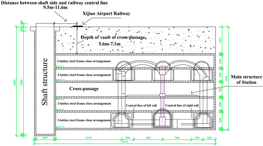
FIGURE 2. Relationship between the new structure and existing railway line.
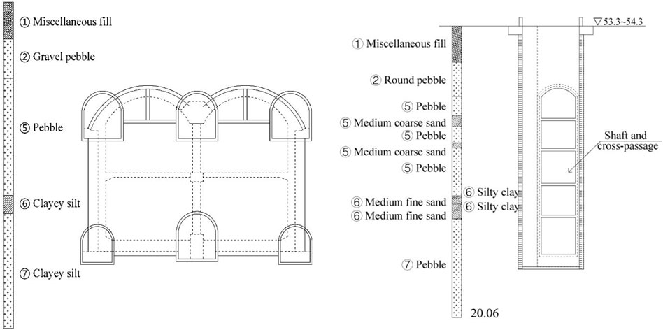
FIGURE 3. Geological condition of Sijiqing Station, shaft, and cross passage.
The cross-passage is to be shallowly buried through the western suburb airport railway (the buried depth of the cross-passage is 5.6–7.1 m) due to the construction shaft is very close to the existing western suburban airport railway (the distance between the sideline of the shaft and the center line of the railway is 9.5–11.6 m). In the process of tunnel construction under the existing railway, the maximum stratum deformation caused by construction generally occurs in the middle line of the tunnel. The ground deformation is transmitted upward, and the roadbed, and rail are deformed together (Figure 4) (He et al., 2015). The construction of the shaft and cross-passage of Sijiqing Station will certainly affect the normal use of the airport railway in the western suburbs. Therefore, to meet the requirements of the existing railway roadbed and rail deformation control values (Table 1) (China Railway Cooperation, 2014; China Railway Cooperation, 2019), the technical measures of line reinforcement and stratum reinforcement (Wang et al., 2019; Li et al., 2022; Nakajima et al., 2022), as well as reasonable construction methods of shafts and cross-passageways should be adopted (Song et al., 2018; Lu et al., 2019; Wu et al., 2019; Zhang et al., 2021; Ma et al., 2022).
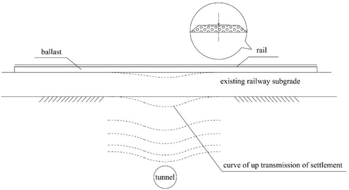
FIGURE 4. Ground deformation transfer path during tunnel excavation under-passing railway line.
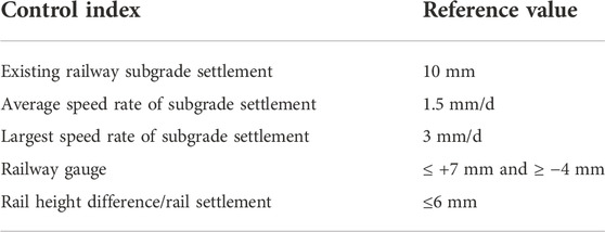
TABLE 1. Control value index of roadbed and rail of existing railway line.
According to the risk grade of the project, past experience, actual site conditions, and relevant technical literature (Feng and Wang, 2000), the track, roadbed, and roof strata are strengthened with the idea of “reinforcement before construction, integral reinforcement of track roadbed, advance support of shaft transverse hole.”
Firstly, drill holes with a drill, and insert the hot rolled seamless steel pipe with an outer diameter of 42 mm and a thickness of 3.25 mm. The length of the steel pipe was adjusted according to the grouting depth, and then the pipe was arranged and drained at a distance of 2 m along the road direction. Small catheters can be used in reverse with each other, and no grouting is required within 2 m of the subgrade height. The roadbed reinforcement is shown in Figure 5. In this study, the No. 1 and No. 2 shafts and cross-passage (the shafts and cross-passage are collectively referred to as passages, the same below) were reinforced 50 m along the direction of the railway line. Passageways 3 and 4 were reinforced for 45 m along the railway line. Along the direction of the vertical railway line, the railway centerline is reinforced by 6 m on each side (Table 2).
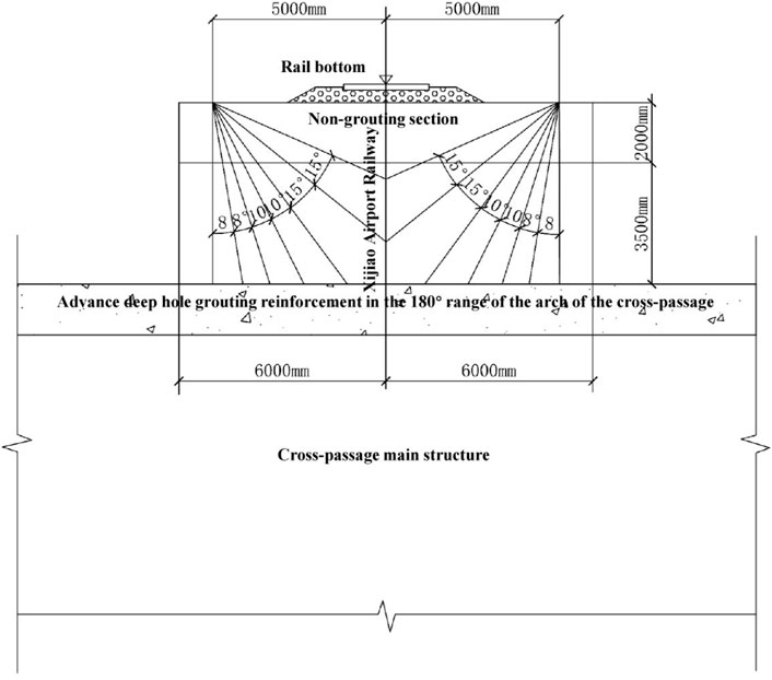
FIGURE 5. Railway subgrade strengthening cross-section.
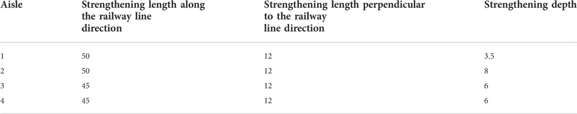
TABLE 2. Subgrade grouting scope (m).
The four construction passageways of Sijiqing Station all need to be reinforced by roadbed and rail. Rail reinforcement is discussed by taking the construction area of channel 1 as an example (channels 2, 3, and 4 are similar). Rail reinforcement sets up supporting piles with a diameter of 1.25 m on both sides of the construction channel. The distance between the edge of the pile and the outer edge of the channel structure is about 2 m, and a total of four supporting piles are arranged at each channel. A crown beam is arranged on the supporting pile, and an I40b I-steel beam is arranged on the crown beam (that is, the crossbeam is supported on the crown beam). Along the direction of the line, the crossbeam is cyclically interspersed between the existing sleepers with a spacing of 0.6 and 1.2 m, with an average spacing of 0.9 m I45b I-steel longitudinal beams are arranged along both sides of the line on the crossbeam, which are arranged in a bundle and connected with the crossbeam with U-shaped bolts. The track reinforcement layout in the construction area of Channel 1 is shown in Figure 6 and Figure 7.
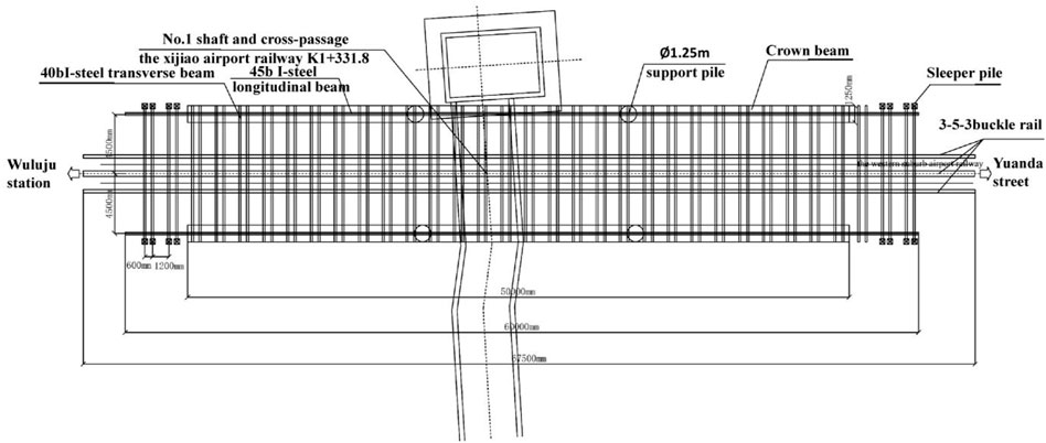
FIGURE 6. Rail reinforcement arrangement plane layout of No.1 passageway construction area.
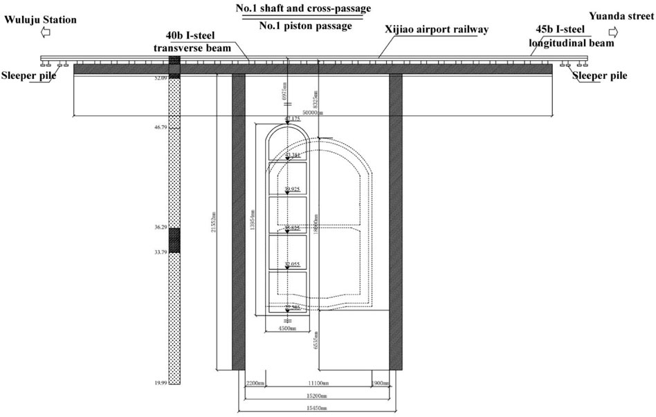
FIGURE 7. Rail reinforcement arrangement longitudinal section of No.1 passageway construction area.
The roof arch of the first floor of each transverse passage is reinforced by deep hole grouting. A total of 14 holes are arranged along the arch (the distance between the holes is about 60 cm), the angle between the hole and the excavation direction of the transverse channel is 6°–27°, and the longitudinal length is 10–12 m. The range of grouting is 1.5 m on the outside of the primary branch and 0.5 m on the inside. The deep-hole grouting pressure is controlled at around 0.5–0.8 MPa according to the formation conditions, and the arch deep-hole grouting reinforcement profile is shown in Figure 8. The side of the shaft near the Xijiao railway is reinforced by advanced grouting with a small conduit.
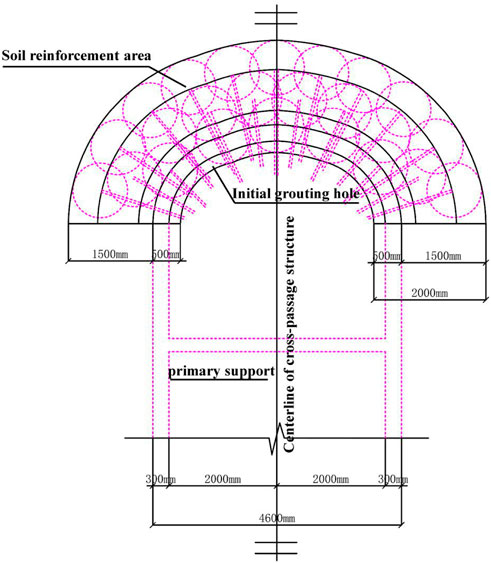
FIGURE 8. Cross section of cross passage deep-hole grouting strengthening.
Sijiqing Station is excavated from four horizontal channels in two directions, with a total of six small pilot holes. In the process of underground excavation construction, it is carried out strictly in accordance with the eighteen-character principle of “pipe advance, strict grouting, short excavation, strong support, early closure, and diligent measurement,” so as to achieve advanced technology, safe adaptation, reasonable economy, convenient construction and ensuring quality. The structural design meets the requirements of strength, stiffness, stability, durability, and so on (Li et al., 2005; Ponomarev and Zakharov, 2015).
Shaft construction is carried out by the inverted hanging shaft wall method (Liu et al., 2015) in accordance with the principle of “partial excavation, excavation with support.” The contour of the shaft is 5.3 × 7.6 m, and the headroom is 4.6 × 6.9 m. The initial support adopts C25 concrete with hanging net injection. The initial support thickness is 0.35 m, during which one pin of the grid steel frame is erected every 0.75 m. A small pipe grouting is set at a horizontal spacing of 0.5 m on the side of the well wall near the railway to reinforce the stratum. Shaft construction in strict compliance with the principle of “digging eighteen characters” policy, timely grouting behind the initial support, to ensure construction safety. The earthwork of the shaft is excavated by manual excavation. The shaft is excavated by manual dig, part ① is firstly excavated, steel mesh toward soil is set after excavation completion, the lattice steel frame of part ① is erected, the connecting steel in quincunx layout (1 × 1 m spacing) is laid, steel mesh back to the soil is set. The lap joint length of steel mesh is 15 cm. Then, shotcreting was carried out to close primary support. Part ② of the shaft is excavated, and the primary support of part ② is the same as part ①. When the primary support of part ② is closed the next cycle of excavation will be carried out. The partial excavation procedure is shown in Figure 9.
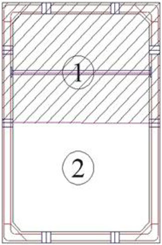
FIGURE 9. Construction procedure of shaft excavation.
Pilots and steps are adopted to excavate cross-passage (Tan et al., 2021; Xu et al., 2021). Temporary bottom sealing is done when the shaft is excavated to 1.5 m below the inverted arch of each pilot. The horse head gate lattice steel frame will be chiseled out when the arch advanced small pipe grouting and deep hole grouting at the first layer pilot are completed. The first layer pilot is excavated by the bench step method, and the corresponding primary support is carried out till to sealing the end of the first pilot. Then, the other four pilots are constructed. Stagger back and forth 8 m for each pilot till to the fifth pilot end sealing. The construction procedure of shaft and cross-passage is listed in Table 3.
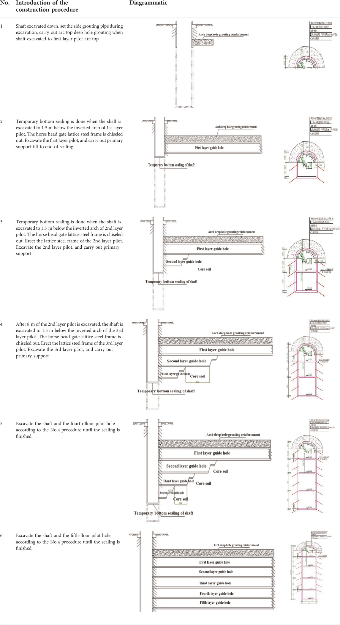
TABLE 3. The construction procedure of shaft and cross-passage.
Aiming at the construction of the No.1 shaft and cross passage of Sijiqing Station through the airport railway, according to the relevant basic data, the ANSYS finite element analysis software is used to establish a three-dimensional construction model to simulate different construction conditions. The initial condition of three-dimensional calculation is that the new project has not yet been constructed, and it is considered that the existing airport railway in the western suburbs and its ancillary structure and stratum are in a state of deformation and stability. Considering the spatial effect in the construction process, three-dimensional calculation and analysis are used to model the excavation area of the new section and the structure of the existing line. The three-dimensional structural model is shown in Figure 10. The range of the model is limited in this calculation in order to ensure the sufficient calculation accuracy of the three-dimensional model and minimize the convergence time. The upper boundary of the model is taken from the surface, and the lower boundary is 40.0 m below the surface. The width of the model is 40 m (8D ∼ D is the width of the horizontal channel) and the longitudinal length is 60 m. The distance between the bottom of the shaft and the lowest edge of the model is 13 m, the buried depth of the cross-passage is 7.1 m, and the vertical distance between the edge of the shaft and the center line of the track is 9.5 m. The cross-section of the shaft is 5.3 × 7.6 m, and the depth is 29 m.The origin of the model coordinates is located at the upper left corner of the shaft edge. The positive direction of the X-axis of the coordinate is the transverse channel excavation direction, the negative direction of the Y-axis is the shaft excavation direction, and the Z-axis direction is the cross-passage width. The model adopts lateral constraints around and vertical constraints at the bottom, and the surface is a free surface. The unit type is Solid185. The primary support of the shaft is C25 with 0.35 m thickness, and small pipe grouting is carried out 2 m below the ground surface to strengthen the ground soil at the side close to the existing railway. The cross-passage is excavated dividing into five layers. Arch top strengthening soil is simulated as an equivalent soil with 1.5 m thickness along 180° scope. In this paper the artifacts deformation is studied as small deformation, and it is considered that there is no separation between components, so it is considered as continuum model. The railway strengthening, small pipe grouting strengthening, and deep hole grouting strengthening are realized by increasing material physical and mechanical parameters.
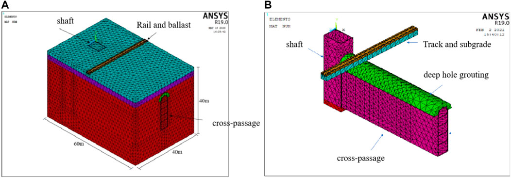
FIGURE 10. Calculation model of shaft and cross passage. (A) is a model for whole ground soil; (B) is the shaft, cross-passage under-passing existing railway.
The stratum element filling layer, round gravel layer, and pebble layer are divided based on the geological prospecting report and related technical data. The corresponding physical and mechanical parameters are shown in Table 4, and the parameters of shafts, horizontal channels, and solid materials are shown in Table 5.
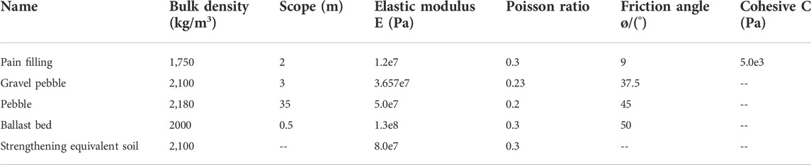
TABLE 4. Ground soil parameters.
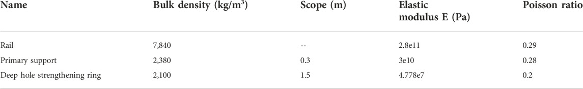
TABLE 5. Shaft and passage structure material parameters.
The software numerical simulation stage is divided into 18 stages and 109 load sub-steps according to the construction plan. There is footage for every 2 m of the cross-passage for excavation, and a cycle for the advance of the small conduit and deep hole grouting every 8 m. The specific steps of each construction stage are shown in Table 6.
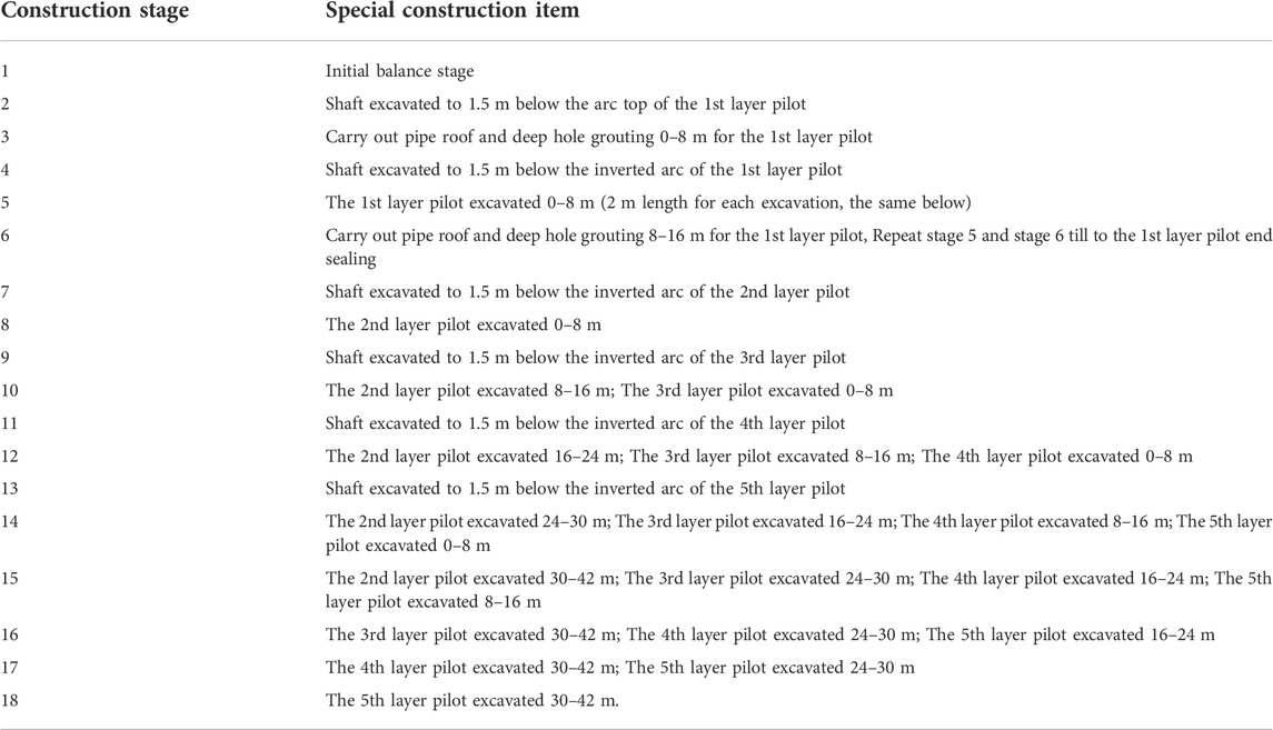
TABLE 6. Construction procedures in numerical simulation.
Combined with the characteristics of the project, five typical steps are analyzed in the numerical calculation results of the stratum, which are: 1) the construction of the first level guide tunnel runs from below through the airport railway, 2) the construction of the second level guide tunnel runs from below through the airport railway, 3) the construction of the third-floor level guide tunnel runs from below through the airport railway, 4) the construction of the fourth-floor level guide tunnel runs from below through the airport railway 5) the construction of the fifth-floor level guide tunnel runs from below through the airport railway.
The ANSYS finite element simulation results were extracted to obtain the stratum vertical displacement cloud map (Figure 11) when the vertical shaft and cross-passage pass through the guide tunnel at each layer of the existing railway after railway reinforcement. According to the cloud image analysis, the maximum vertical displacement of surface settlement caused by the construction process is the area on both sides of the track at the midline position of the cross-passage when the transverse passage passes under the existing line. With the increase in the horizontal distance between the two sides of the cross-passage, the settlement amount becomes smaller and smaller, and the maximum surface settlement amount is -7.3 mm. The settlement deformation of the strengthened area is small, while the settlement of the unstrengthened area is obvious in the surface settlement cloud diagram of the area where the midline track of the transverse passage is located. On both sides of the rail boundary, the settlement is basically unchanged. There is an upward uplift state on the left side, which is affected by the boundary and can be ignored. There is a large amount of surface settlement in the area under the middle line of the cross-passage, and the settlement gradually decreases with the increase of the distance between the two sides of the middle line of the cross-passage (Guo et al., 2018; Jiang et al., 2018; Zhang et al., 2018a; Yu and Geng, 2019). When the second layer guide tunnel is excavated through the existing line, it has little influence on the surface settlement and track settlement. The settlement produced at this time is basically the settlement caused by the surface and rail when the first layer of the guide tunnel is excavated through the existing line. The cloud map of the ground settlement is caused by the cross-passage passing through.
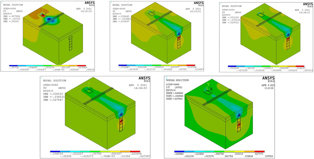
FIGURE 11. Ground surface settlement cloud chart of pilots under-passing existing railway line.
In a word, the vertical displacement cloud images of steps 1–5 are symmetrically distributed relative to the center line of the cross-passage. The surface settlement is getting larger and larger with the construction and excavation of the cross-passage. The maximum vertical displacement values of steps 1 to 5 are −7.3, −33.44, −33.129, −36.533, and −40.866 mm, respectively, which do not exceed the standard values of monitoring and measurement (surface subsidence ≤60 mm). It shows that the construction is safe after taking reinforcement measures.
The surface settlement curve of monitoring section Ⅱ (Figure 12) is shown in Figure 13 when the guide tunnel of each layer is constructed through the existing line. It can be seen from the figure that the surface subsidence of monitoring section Ⅱ caused by the excavation of each layer is an axisymmetric distribution across the middle line of the channel. The surface subsidence is larger in the range of 0–15 m on both sides of the centerline of the cross-passage, which is about 3–4 times the width of the transverse channel, and the settlement curve is similar to the typical Peck settlement curve. When the guide tunnel of each layer is excavated through the existing line, the maximum settlement position of the monitoring section Ⅱ occurs at the middle line of the cross-passage, and the maximum settlement and settlement of each step are shown in Table 7. It can be seen from the table that the surface subsidence of monitoring section Ⅱ accounts for the largest proportion in the stage of excavation and sealing of the first layer guide tunnel, followed by the excavation of the second layer guide tunnel. The excavation of a three-layer guide tunnel to five-layer guide tunnel has little influence on the surface. Figure 12 instantaneous subsidence curves of DB-08-01 and DB-08-02 surface survey points at the middle line of the cross-passage are shown in Figure 14. The surface monitoring point is in a state of uplift when the palm face of the cross-passage excavation does not pass through the existing line. The reason for this is that the deep hole grouting (pressure 0.5–0.8 MPa) is carried out before the t cross-passage is excavated, which makes the surface uplift (Zhang et al., 2018a; Zhao et al., 2021). When the guide hole of the first layer of the cross-passage is excavated through the existing line (that is, step 1), the settlement value of the DB-08-01 monitoring point is −4.56 mm, accounting for about 76.305% of the total settlement. The settlement value of the DBMI 08-02 monitoring point is −5.361 mm, accounting for about 53.87% of the total settlement. The sudden change of settlement will occur at the monitoring point of step 1 and step 2, and the change of the settlement curve of the monitoring point from step 3 to step 5 is not obvious.
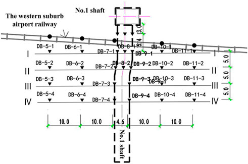
FIGURE 12. Points arrangement of site ground surface settlement monitoring for 1# shaft and passage.
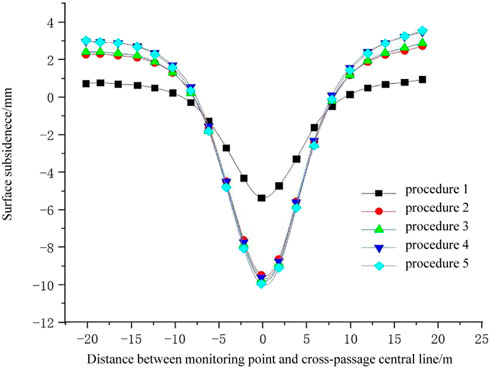
FIGURE 13. Ground surface settlement curve of cross Section 2 during pilots under-passing existed railway line.
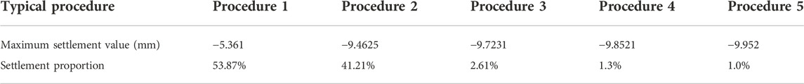
TABLE 7. Statistic value of ground surface settlement of monitoring Section 2.
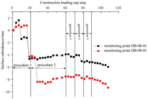
FIGURE 14. Settlement curve of monitoring points.
Through the numerical simulation of the shaft and cross passage construction, the final settlement monitoring curve simulation results of the left and right tracks of the Xijiao airport railway are obtained as shown in Figure 15. The maximum settlement values of the left and right rails caused by the shaft and the cross-passage passing through the airport railway are located in the center of the cross-passage. The maximum height difference between the left and right rails is 0.1955 mm, which does not exceed the allowable limit (≤6 mm). Figure 16 shows the settlement curve produced by the left rail during the construction of each cross-passage through the existing line. It can be seen from the diagram that when each layer of the guide tunnel is constructed under the existing line, the main settlement occurs in the excavation of the first layer guide tunnel, and the settlement value is -3.98 mm. The maximum difference between the settlement value generated by steps 2 to 5 and that generated by step 1 is 0.33 mm. To sum up, the track settlement mainly occurs in the excavation of the first layer guide tunnel during the excavation of the shaft and transverse passage, and the settlement is symmetrically distributed on both sides of the middle line of the transverse channel (Gao et al., 2022; Faustin et al., 2018; Auvinet-Guichard, G et al., 2010). This result may be due to the settlement caused by the excavation of the first and second-floor guide tunnel, and the reverse support force on the surface after the support reduces the influence of subsequent guide tunnel excavation.
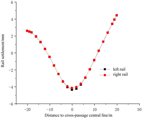
FIGURE 15. Rail settlement curve.
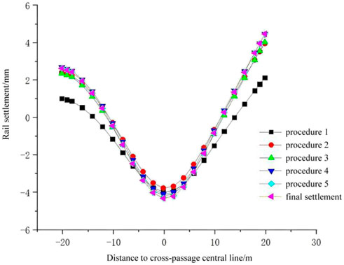
FIGURE 16. Left rail settlement curve during pilots under-passing existed railway line.
Cloud diagram of track and subgrade settlement after reinforcement of existing line, as shown in Figure 17. The maximum settlement value of the track and subgrade after the reinforcement of the existing line appears at the position where the cross passage passes through the track of the existing line, and the farther from the two sides of the cross passage, the smaller the settlement of the track and subgrade. However, the total settlement did not exceed the allowable deformation of the track. The maximum settlement occurred at the center line of the right rail cross passage of the track, with a value of -5.10 mm.
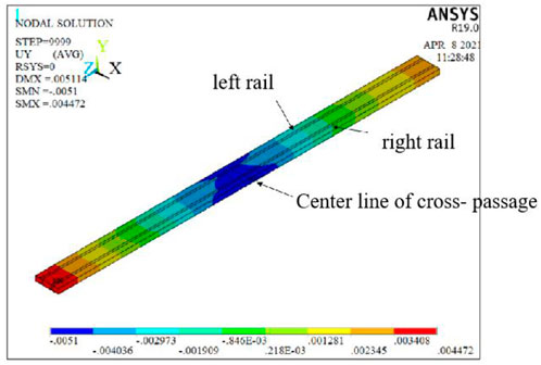
FIGURE 17. Cloud chart of track and subgrade settlement after reinforcement.
The simulation results of monitoring section Ⅰ, monitoring section Ⅱ, and monitoring point DB-08-02 are compared with the field monitoring data. The corresponding numerical simulation and field monitoring data are shown in Figure 18, Figure 19, and Figure 20 respectively. The measured and numerical simulation values of the final surface settlement of section Ⅰ and section Ⅱ are the largest in the center of the transverse passage, and the settlement is larger in the range of 0–15 m on both sides of the center of the transverse passage. The trend of the field monitoring result is similar to that of the numerical simulation settlement curve. In the process of construction, the construction plan will be adjusted in time according to monitoring data and feedback. Therefore, the measured data will fluctuate slightly. But on the whole, the numerical simulation data are in good agreement with the field monitoring data. The numerical simulation of the monitoring point DB-08-02 and the maximum settlement value of the field monitoring occurred after the completion of the excavation of the transverse passage. The maximum settlement value of numerical simulation is -9.352 mm and the maximum settlement value of on-site monitoring is -9.68 mm, which all meet the requirements of settlement monitoring and control standards. In addition, the two curves have a sudden change of settlement when the excavation face passes under the monitoring point. The changing trend of the two curves in the construction process of the shaft and transverse passage is roughly similar.
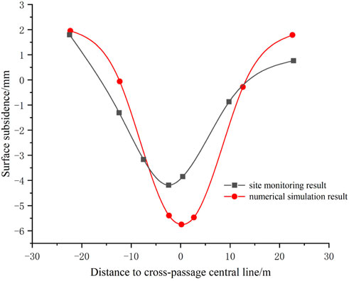
FIGURE 18. Comparison of ground surface settlement values between numerical analysis and site monitoring for Section 1.
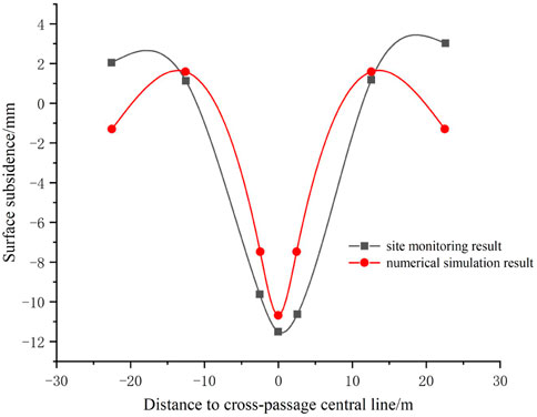
FIGURE 19. Comparison of ground surface settlement values between numerical analysis and site monitoring for Section 2.
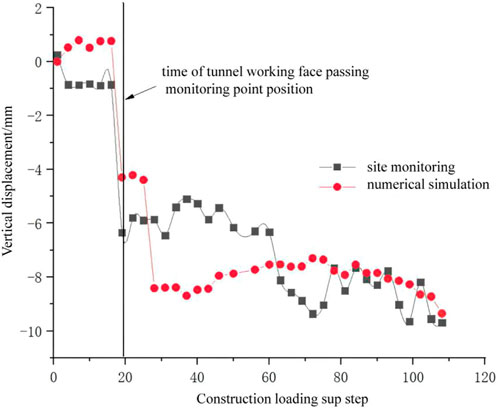
FIGURE 20. Comparison of settlement values between numerical analysis and site monitoring for point DB-08-02.
Through the numerical simulation analysis, it is verified that the construction scheme of the shaft and transverse passage under the existing railway of Beijing Metro Line 12 Sijiqing Station and the reinforcement measures for the existing railway are reasonable. Some revelations can be obtained from it for reference for similar projects in the future.
1) The overall construction of “reinforcement before construction, integral reinforcement of track roadbed and advance support of shaft transverse hole” is feasible. The calculation results show that construction scheme has little disturbance to the stratum and the existing railway, and the effect is good. Chang et al., 2021, Feng and Wang, 2000, He, 2015, Huang et al., 2020, Railway Cooperation, 2014, Railway Cooperation, 2019, Zhang et al., 2018b, Zhang et al., 2018c.
2) The stratum subsidence is mainly caused by the construction of the first-layer guide tunnel of the cross-passage (about 54% of the total settlement) and the construction of the second-layer guide tunnel (about 41% of the total settlement). The influence of the construction of the third to fifth-floor guide tunnel is relatively small. This may be due to the settlement caused by the excavation of the first and second floor guide tunnel, and the reverse supporting force on the surface after the support reduces the impact of the subsequent excavation of the guide tunnel.
3) The surface subsidence of monitoring section II caused by excavation of each layer is axisymmetric distribution across the middle line of the channel. The surface subsidence is larger in the range of 0 — 15 m on both sides of the centerline of the cross-passage, which is about 3 - 4 times the width of the transverse channel. The settlement curve is similar to the typical Peck settlement curve. In addition, the subsidence curve of Xijiao Airport Railway track is similar to the ground subsidence curve, but the settlement value is smaller.
The original contributions presented in the study are included in the article/Supplementary Material, further inquiries can be directed to the corresponding author.
LL: Conceptualization, Methodology, Software, Investigation, Formal Analysis, Writing—Original Draft; GX: Data Curation; RL: Investigation; ZF: Resources, Supervision; HC: Software; SW: Validation; WX: Writing—Review and Editing; BH: Supervision; CM: Writing—Original Draft; QS: Conceptualization, Funding Acquisition, Resources, Supervision, Writing—Review and Editing.
Author GX was employed by the companies The 4th Engineering Company and The 3rd China Railway Engineering Group Ltd., Co.
The remaining authors declare that the research was conducted in the absence of any commercial or financial relationships that could be construed as a potential conflict of interest.
All claims expressed in this article are solely those of the authors and do not necessarily represent those of their affiliated organizations, or those of the publisher, the editors and the reviewers. Any product that may be evaluated in this article, or claim that may be made by its manufacturer, is not guaranteed or endorsed by the publisher.
Auvinet-Guichard, G., Rodriguez-Rebolledo, J. F., and Rangel-Nunez, J. L. (2010). Construction of deep tunnel shafts in Mexico city soft clays by the flotation method. Acta Geotech. 5 (1), 63–68. doi:10.1007/s11440-010-0115-2
Chang, L., Sakpal, N. P., Elberink, S. O., and Wang, H. Y. (2021). Railway infrastructure classification and instability identification using sentinel-1 SAR and laser scanning data. Sensors (Basel) 20 (24), 7108. doi:10.3390/s20247108
Chang, Y. S., Jo, S. J., Lee, Y. T., and Lee, Y. (2021). Population density or populations size. Which factor determines urban traffic congestion? Sustainability 13 (8), 4280. doi:10.3390/su13084280
Chang, Z., Du, Z., Zhang, F., Huang, F., Chen, J., Li, W., et al. (2020). Landslide susceptibility prediction based on remote sensing images and GIS: Comparisons of supervised and unsupervised machine learning models. Remote Sens. 12, 502. doi:10.3390/rs12030502
Chen, Z. W., Zhai, W. M., Cai, C. B., and Sun, Y. (2015). Safety threshold of high-speed railway pier settlement based on train-track-bridge dynamic interaction. Sci. China Technol. Sci. 58 (2), 202–210. doi:10.1007/s11431-014-5692-0
Dong, X., Mei, L., Yang, S. Y., and He, L. (2021). Deformation response research of the existing subway tunnel impacted by adjacent foundation pit excavation. Adv. Mater. Sci. Eng. 2021, 1–11. doi:10.1155/2021/5121084
Faustin, N. E., Elshafie, M. Z. E. B., and Mair, R. J. (2018). Case studies of circular shaft construction in London. Proc. Institution Civ. Eng. - Geotechnical Eng. 171 (5), 391–404. doi:10.1680/jgeen.17.00166
Feng, W. X., and Wang, K. L. (2000). Design and construction of underpass bridge (in Chinese). Shijiazhuang: Hebei Science and Technology Press.
Gao, T. C., Li, Z. H., Gao, Y., Schonfeld, P., Feng, X., Wang, Q., et al. (2022). A deep reinforcement learning approach to mountain railway alignment optimization. Comput. aided. Civ. Eng. 37 (1), 73–92. doi:10.1111/mice.12694
Guo, H. F., Yao, A. J., Zhang, J. T., Zhou, Y. J., and Guo, Y. F. (2018). Impact of high-rise buildings construction process on adjacent tunnels. Adv. Civ. Eng. 2018, 5804051.1–5804051.12. doi:10.1155/2018/5804051
He, Wei (2015). Research on the subgrade settlement and controlling measures of high-speed railway during the under-passing of shallow Metro tunnel construction[D]. Beijing jiaotong University. China, Beijing, in Chinese.
Huang, F., Cao, Z. S., Jiang, S. H., Zhou, C. B., and Guo, Z. Z. (2020). Landslide susceptibility prediction based on a semi-supervised multiple-layer perceptron model. Landslides 17, 2919–2930. doi:10.1007/s10346-020-01473-9
Hu, Z. Q., Ma, B., Chen, X. Z., and Chen, L. L. (2021). Study on sensitivity parameters analysis of grouting reinforcement underpassing existing subway tunnel by numerical modeling. Adv. Civ. Eng. 2021, 1–13. doi:10.1155/2021/8868216
Huang, F., Cao, Z. S., Guo, J. F., Jiang, S. H., and Guo, Z. Z. (2020). Comparisons of heuristic, general statistical and machine learning models for landslide susceptibility prediction and mapping. CATENA 191, 104580. doi:10.1016/j.catena.2020.104580
Huang, F., Zhang, J., Zhou, C. B., Wang, Y. H., Huang, J. S., and Zhu, L. (2020). A deep learning algorithm using a fully connected sparse autoencoder neural network for landslide susceptibility prediction. Landslides 17 (01), 217–229. doi:10.1007/s10346-019-01274-9
Jiang, S. H., Huang, J., Huang, F., Yang, J. H., Yao, C., and Zhou, C. B. (2018). Modelling of spatial variability of soil undrained shear strength by conditional random fields for slope reliability analysis. Appl. Math. Model. 63, 374–389. doi:10.1016/j.apm.2018.06.030
Jin, D. L., Yuan, D. J., Li, X. G., and Zheng, H. T. (2018). Analysis of the settlement of an existing tunnel induced by shield tunneling underneath. Tunn. Undergr. Space Technol. 81, 209–220. doi:10.1016/j.tust.2018.06.035
Lan, X. D., Zhang, X., Li, X. H., Li, Z., Liu, Y., and Xia, M. (2022). Model experiment on surface subsidence induced by excavation of shallow small-spacing tunnels. Environ. Earth Sci. 81 (4), 133. doi:10.1007/s12665-022-10226-x
Li, J., Li, J. K., Cai, Y. C., Wu, D., Guo, C., Zhao, W., et al. (2022). Application of artificial freezing method in deformation control of subway tunnel. Adv. Mater. Sci. Eng. 2022, 1–21. doi:10.1155/2022/3251318
Li, Z. K., Liu, H., Dai, R., and Su, X. (2005). Application of numerical analysis principles and key technology for high fidelity simulation to 3-D physical model tests for underground caverns. Tunn. Undergr. Space Technol. 20 (4), 390–399. doi:10.1016/j.tust.2005.01.004
Liu, S. S. (2014). Study on the influence of subway tunnel construction on the stability of existing railway subgrade (in Chinese). Beijing Jiaotong University, China, Beijing.
Liu, X. Z., Li, X. F., Sang, Y. L., and Lin, L. L. (2015). Experimental study on normal fault rupture propagation in loose strata and its impact on mountain tunnels. Tunn. Undergr. Space Technol. 49, 417–425. doi:10.1016/j.tust.2015.05.010
Lu, Y., Tan, Y., and Lan, H. L. (2019). Full-scale load testing of 75-90-m-Long post-grouted drilled shafts in suzhou stiff clay. J. Test. Eval. 47 (1), 284–309. doi:10.1520/JTE20170442
Ma, Y. Z., Zhu, Y. H., Pan, H. J., Niu, F. S., and Mei, Q. J. (2022). Grouting effects of fully mechanized tunneling method for metro cross-passage construction in soil strata. Arab. J. Sci. Eng. doi:10.1007/s13369-022-07035-6
Nakajima, S., Sanagawa, T., Matsumaru, T., and Koda, M. (2022). Recent research development and their applications on aseismic reinforcement of existing railway Earth structures. Soils Found. 62 (1), 101104. doi:10.1016/j.sandf.2021.101104
Ponomarev, A. B., and Zakharov, A. V. (2015). Analysis of the interaction between energy-efficient foundations and soil mass. Soil Mech. Found. Eng. 52 (4), 232–237. doi:10.1007/s11204-015-9333-9
Qian, W. P., Qi, T. Y., Zhao, Y. J., Le, Y. Z., and Yi, H. Y. (2019). Deformation characteristics and safety assessment of a high-speed railway induced by undercutting metro tunnel excavation. J. Rock Mech. Geotechnical Eng. 11 (1), 88–98. doi:10.1016/j.jrmge.2018.04.014
Railway Cooperation, China, (2014). Public works safety rules for ordinary speed railway, No.272. Beijing: China Railway Press.
Railway Cooperation, China, (2019). Rules for repair of ordinary speed railway linesTG/GW102-2019. Beijing: China, Railway Press.
Ramadan, A. N., Jing, P., Zhang, J. X., and Zohny, H. N. E. D. (2021). Numerical analysis of additional stresses in railway track elements due to subgrade settlement using FEM simulation. Appl. Sci. (Basel). 11 (18), 8501. doi:10.3390/app11188501
Song, Z. P., Cao, Z. L., Wang, J. B., Wei, S., Hu, S., and Niu, Z. (2018). Optimal analysis of tunnel construction methods through cross passage from subway shaft. Adv. Civ. Eng. 2018, 1–14. doi:10.1155/2018/5181954
Tan, Z. S., Zhou, Z. L., Kong, H., Zhao, B., and Zhao, J. P. (2021). Single excavation face method for super-large-span bifurcated tunnels. Proc. Institution Civ. Eng. - Geotechnical Eng. 174 (4), 1–13. doi:10.1680/jgeen.20.00222
Tao, Y. H., and Rao, J. Y. (2022). Construction analysis of guiyang metro passing across guiyang railway station in karst zone. Tunn. Undergr. Space Technol. 126, 104541. doi:10.1016/j.tust.2022.104541
Tu, H. L., Zhou, H., Qiao, C. S., and Gao, Y. (2020). Excavation and kinematic analysis of a shallow large-span tunnel in an up-soft/low-hard rock stratum. Tunn. Undergr. Space Technol. 97, 103245. doi:10.1016/j.tust.2019.103245
Wang, F. (2021). Evaluation of surface subsidence during TBM construction of urban tunnels based on generalized rheological theory. Geotech. Geol. Eng. (Dordr). 40 (3), 1323–1330. doi:10.1007/s10706-021-01965-y
Wang, W., Han, Z., Deng, J., Zhang, X. Y., and Zhang, Y. F. (2019). Study on soil reinforcement param in deep foundation pit of marshland metro station. Heliyon 5 (11), e02836. doi:10.1016/j.heliyon.2019.e02836
Wu, B., Liu, W., Shi, P. X., Xu, X. Y., and Liu, Y. J. (2022). A case study of newly tunnels over-crossing the existing subway tunnels. Int. J. Distrib. Sens. Netw. 18 (3), 155013292210871. doi:10.1177/15501329221087183
Wu, K., Cui, S. S., Zhang, Q. J., Zheng, Z., Jiahui, Z., and Yalin, Y. (2019). Mechanical mechanism analysis and influencing factors of subway cross passage construction. Lat. Am. J. solids Struct. 16 (6), e198. doi:10.1590/1679-78255512
Xu, D. P., Huang, X., Jiang, Q., Li, S., Zheng, H., Qiu, S., et al. (2021). Estimation of the three-dimensional in situ stress field around a large deep underground cavern group near a valley. J. Rock Mech. Geotechnical Eng. 13 (3), 529–544. doi:10.1016/j.jrmge.2020.11.007
Yang, G., Wang, W., Sheng, X., Yang, F., Kong, L., He, J., et al. (2019). Tissue characteristics of culprit lesion and myocardial tissue-level perfusion in non-ST-segment elevation acute coronary syndromes: The EARLY-MYO-ACS study. Int. J. Cardiol. 3, 32–38. doi:10.1016/j.ijcard.2019.02.010
Yang, M., Li, H. R., Li, N., and Yang, S. (2020). Effect of subway excavation with different support pressures on existing utility tunnel in xi'an loess. Adv. Civ. Eng. doi:8818949, 1–14. doi:10.1155/2020/8818949
Yang, Z. Q., and Wang, X. T. (2020). Influence of metro tunnel excavation on deformation of existing pedestrian underpass in changzhou railway station platform. IEEE Access 8, 55860–55871. doi:10.1109/ACCESS.2020.2981343
Yu, S. H., and Geng, Y. C. (2019). Influence analysis of underground excavation on the adjacent buildings and surrounding soil based on scale model test. Adv. Civ. Eng. 2019, 1–15. doi:10.1155/2019/6527175
Zhang, C. P., Zhang, X., and Fang, Q. (2018). Behaviors of existing twin subway tunnels due to new subway station excavation below in close vicinity. Tunn. Undergr. Space Technol. 81, 121–128. doi:10.1016/j.tust.2018.07.020
Zhang, G. H., Jiao, Y. Y., Ma, C. X., Wang, H., Chen, L. B., and Tang, Z. C. (2018a). Alteration characteristics of granite contact zone and treatment measures for inrush hazards during tunnel construction - a case study. Eng. Geol. 235, 64–80. doi:10.1016/j.enggeo.2018.01.022
Zhang, R. M., Cheng, X. L., Li, Y., Pan, L., and Xia, J. H. (2021). Research on the ground subsidence mechanism of cross passage caused by freezing method construction. Adv. Civ. Eng. 2021, 1–9. doi:10.1155/2021/6622177
Zhang, W. J. (2022). Countermeasures for urban traffic congestion in China from the perspective of system dynamics. Comput. Intell. Neurosci. 2022, 1–15. doi:10.1155/2022/3509902
Zhang, X. M., Yang, J. S., Zhang, Y. X., and Gao, Y. F. (2018b). Cause investigation of damages in existing building adjacent to foundation pit in construction. Eng. Fail. Anal. 83, 117–124. doi:10.1016/j.engfailanal.2017.09.016
Zhang, X., Zhang, C. P., and Wang, J. C. (2018c). Effect of closely spaced twin tunnel construction beneath an existing subway station: A case study. J. Test. Eval. 46 (4), 20160563–20161573. doi:10.1520/JTE20160563
Zhang, Z. Y., Jin, X. G., and Luo, W. (2019). Numerical study on the collapse behaviors of shallow tunnel faces under open-face excavation condition using mesh-free method. J. Eng. Mech. 145 (11), 04019085. doi:10.1061/(ASCE)EM.1943-7889.0001661
Zhao, M. J., Cheng, Y., Song, Z. P., Wang, T., Zhang, Y. W ., Gong, Y. T., et al. (2021). Stability analysis of tbm tunnel undercrossing existing high-speed railway tunnel: A case study from yangtaishan tunnel of shenzhen metro line 6. Adv. Civ. Eng. 2021, 1–18. doi:10.1155/2021/6674862
Keywords: subway station, cross-passage, under-passing, existing railway, influence analysis
Citation: Liu L, Xu G, Li R, Fang Z, Chen H, Wu S, Xu W, Han B, Ma C and Shen Q (2023) Tunneling construction technology of shafts and cross-passages under strictly controlling deformation of the existing railway. Front. Earth Sci. 10:1064772. doi: 10.3389/feart.2022.1064772
Received: 08 October 2022; Accepted: 15 November 2022;
Published: 16 January 2023.
Edited by:
Zizheng Guo, Hebei University of Technology, ChinaReviewed by:
Yang Chen, Sun Yat-sen University, ChinaCopyright © 2023 Liu, Xu, Li, Fang, Chen, Wu, Xu, Han, Ma and Shen. This is an open-access article distributed under the terms of the Creative Commons Attribution License (CC BY). The use, distribution or reproduction in other forums is permitted, provided the original author(s) and the copyright owner(s) are credited and that the original publication in this journal is cited, in accordance with accepted academic practice. No use, distribution or reproduction is permitted which does not comply with these terms.
*Correspondence: Qian Shen, c2hlbnFpYW5AaGVqdHh5LmVkdS5jbg==
Disclaimer: All claims expressed in this article are solely those of the authors and do not necessarily represent those of their affiliated organizations, or those of the publisher, the editors and the reviewers. Any product that may be evaluated in this article or claim that may be made by its manufacturer is not guaranteed or endorsed by the publisher.
Research integrity at Frontiers
Learn more about the work of our research integrity team to safeguard the quality of each article we publish.