 Ling Li1
 Ling Yue
94% of researchers rate our articles as excellent or good
Learn more about the work of our research integrity team to safeguard the quality of each article we publish.
Find out more
ORIGINAL RESEARCH article
Front. Earth Sci. , 13 January 2023
Sec. Geohazards and Georisks
Volume 10 - 2022 | https://doi.org/10.3389/feart.2022.1053190
As a key parameter in the design and construction of the Sea Crossing Bridge, the wave and current load on the pile foundation has been the subject of extensive research. The magnitude and distribution of wave and current loads on pile foundations are crucial for the safety of the foundation. Based on Male Airport Island Bridge Project in the Maldives, the wave current force of platform pile and steel casing in different construction stages is investigated, and the horizontal force and bending moment of the foundation under various wave and current parameters are tested using an indoor model. The results are as follows: 1) With the same effective wave height and wave period, the maximum horizontal force and bending moment on the pile exhibit a linear relationship to the wave velocity. Under the same water depth, the combined wave current force is greater than the sum of wave force and simple current force, with a maximum difference of 70%; 2) Under 2-year return period wave and current conditions, the horizontal stress on a single platform pile and steel casing increases linearly with the increase in height, and there will be nonlinear relationship with 10-year return period wave and current conditions; 3) With more platform piles and steel casing, the front row piles have obvious protective effect on the rear row piles, and the horizontal force and bending moment of the overall structure increase nonlinearly.
The bridge foundation of the cross-sea bridge will be subjected to a high-intensity horizontal force due to the action of waves and currents. To ensure the safety and economy of the project, it is necessary to obtain the wave current force accurately during the design and construction. At present, the semi-empirical formula Morison et al. (1950) equation and diffraction theory are extensively used to compute wave loads (Maccamy amd Fuchs, 1954), Code of Hydrology for Harbour and Waterway (JTS 145-2015) (Ministry of Transport, PRC, 2016) also provides related calculation methods for wave current force. However, in practical engineering, the size and shape of structures are complex, making it is challenging to obtain accurate analytical solutions using theoretical formulas. Therefore, the wave (current) force on bridge foundation is often determined using a mathematical model of wave and flow or physical model test.
Based on the wave diffraction theory, Zhang et al. (2018) established a three-dimensional mathematical model of a large scale structure subjected to wave force by using the boundary element method, and the analytical solution of wave force on a circular pier was obtained, which was verified by field measurements, indicating that the calculated values were more consistent with the measured results. However, due to the lack of observational data for diverse wave directions, further verification is required.
Zhou et al. (2015) employed boundary element method (BEM) for numerical computation and physical model testing to analyze the wave current force of bridge foundation respectively and discovered that the calculated value was about 8% larger than the experimental value. Chen (2015) adopted the approach of combining theoretical calculation and model test to analyze the wave force of the pier of the cross-sea bridge under the coupling action of wind and wave, and the difference between the theoretical value and the test value obtained was basically within 30%. The wave current interaction is studied by combining theoretical derivation with numerical calculation, and a wave current force calculation method is proposed for weak coupling and strong coupling (Liu, 2012).
Hu et al. (2012) summarized the existing wave (current) force calculation methods, and believed that for large-size piles and pile group piles, the existing methods make it difficult to accurately calculate the size of the wave (current) force, and there are certain limitations in mathematical model and physical model experiments. The wave and current forces of single pile and pile group structures under different water depths and wave parameters are tested through physical model tests. A three-dimensional numerical flume is established using numerical methods to simulate the action of wave and current on single pile and pile group (Li, 2016; Deng, 2021). It is indicated that the calculation results according to the specification are safer than that of Morison equation for wave load of single pile. The change of structure size will cause the change of wave current load; the maximum horizontal wave current force decreases with the increase of the angle between current and wave incidence direction.
Zhou et al. (2017) used physical model experiments to study the wave (current) force of the offshore wind turbine foundation. The results demonstrated that the model test results were greater than the calculated values of the formula, and the simplified calculation of the formula method caused the results to deviate significantly. Sun et al. (2019) used theoretical calculation and experimental methods to study the wave flow force of the cross-sea bridge pile foundation, and the near flow velocity v1 of the erosion forward was much greater than the flow rate in the actual scouring pit, resulting in the cross-bridge wave flow test result generally being lower than the calculation result, and the calculated value obtained after the correction of the calculation formula being closer to the test value.
In combination with the bridge pile foundation project, according to the theoretical calculation and three-dimensional modeling methods, the formula of wave current force on pile group foundation is proposed, taking into account the phase difference of wave force on each pile due to different positions, and taking into account the protective effect of front piles in pile group, which makes the calculation more reasonable (Huang and Yu, 2009; Dai and Wei, 2021). The variation law of wave current force under different water levels is studied by Wang et al. (2021). It is found that the reflection and blocking effect of wave current force increase with the increase of wave amplitude.
Field tests of pile foundation and three-dimensional (3D) simulation are performed to reveal the interaction mechanism between different pile foundations and the surrounding soil. The results indicate that under cyclic loading, soil particles tend to move towards the foundation, leading to the formation of convective zones (Li et al., 2022a; Li et al., 2022b). The numerical research could provide some new perspectives for the interaction between hybrid pile foundation and surrounding soil under cyclic lateral loading condition.
As the dimension of the pipe pile implemented offshore increases dramatically, a novel 3D torsional soil-pile interaction model is proposed by Zhang et al. (2022a), Zhang et al. (2022b), and the corresponding analytical solution is derived for the 3D dynamic torsional impedance at the pile cross-section. It is found that the impedance at the outer radius would be slightly larger than that at the inner radius. To investigate the kinematic response of offshore piles under vertically propagating S-waves considering hydrodynamic pressure, an analytical framework is developed by Chen et al. (2022). The rationality and accuracy of the proposed mathematical model have been verified by comparing the calculated results with the existing studies.
At present, the method for calculating the wave current force of pile foundation is immature and has limited applicability. In marine environments, the influencing factors are typically complicated, and the results obtained by theoretical calculations are often too large.
In this study, based on the Malé, Maldives -Airport Island Bridge project, the indoor model test method was utilized to study the stress conditions of construction platform piles and steel casing in different construction stages during the deep-water foundation construction of the cross-sea bridge. The variation trend of the maximum horizontal force is tested on single pile and steel casing under different water level, wave and current parameters, and the relationship between wave and current forces is analyzed. Then the variation of wave and current forces on typical pile positions is researched, the protective effect between different pile positions in pile group foundation is studied. In addition, the overall wave and current load of pile group foundation in different construction stages is studied.
Numerical simulation and theoretical calculation methods were widely used on wave current coupling of large-diameter piles in previous studies. In this study, model tests of piles are conducted and different phenomena are observed. It is found that the above coupling relationship changed significantly with water depth, and the coupling effect quite different from the theoretical and numerical simulation results. At the same time, the horizontal force distribution law of each single pile in pile group foundation under the combined action of strong wave and current is studied, and the interaction between piles is analyzed. Due to the complexity of wave current field, the theoretical methods are difficult to accurately calculate the wave and current forces on pile groups, so the test study can provide data support for theoretical research.
Malé, Maldives -Airport Island Bridge is located in north Malé Atoll of Maldives, across the Gaadhoo Koa Strait, connecting the three adjacent islands of Malé Island, Airport Island (Huhul Island), and Hulhumale Island; it is the most significant island connection project in Maldives.
The bridge consists of Bridges, sea reclamation embankments, and roads, with a total length of 2.0 km. The total length of the bridge is 1.39 km, consisting of the main bridge and the approach bridge on both sides of the strait (as shown in Figure 1). The starting pile number of the bridge is K0+100 and the ending pile number is K1+490, and the bridge span is 18 m × 30 m + (100 m + 2 m × 180 m + 140 m + 100 m + 60 m) + 3 m × 30 m.
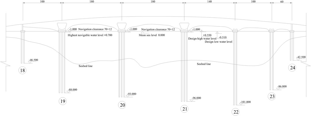
FIGURE 1. Layout of main bridge of malé—airport island bridge in Maldives.
Malé Island, located on the southern edge of the North Malé Atoll in the Maldives, is dominated by coral lagoon landforms on the north side and drowning valley coastal landforms on the south side, with deep troughs on underwater slopes. The Gaadhoo Koa Strait, where the bridge is located, has large waves, rapids, and long wave cycles; the water depth of the strait ranges from 0 to 60 m; the northeast-east side slope of Male Island is steep, and the local water depth exceeds 60 m; the southeastern side of Malé Island has a gentle slope and a slightly shallower water depth of 35–40 m (as shown in Figure 2).

FIGURE 2. Contour map of water level in Gaadhoo Koa strait.
The Maldives archipelago is surrounded by sea areas, and the tides in the vicinity of the project area is regular semi-diurnal tides. According to the survey data, the measured spring tide range in the research region during the spring tide is around 0.90 m, the designed high tide with 10% of the accumulated high tide frequency at the bridge site is 0.55 m, and the designed low tide with 90% of the accumulated low tide frequency is −0.51 m.
The rising and falling tides in the project area are affected by the boundary and terrain of the bay. The channel between the two islands takes on a reciprocating flow pattern. During high tide, the water flow in North Male Atoll flows southeast through the channel, merging with the tidal current on the south side to form a weak backflow zone on the south side of airport Island. At low tide, the flow reverses, creating a clockwise return zone off the coast southwest of Airport Island. The tidal current vector of spring tide is shown in Figure 3.
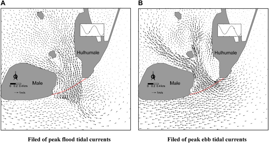
FIGURE 3. Field of tidal currents. (A) Filed of peak flood tidal currents. (B) Filed of peak ebb tidal currents.
The foundations 21# and 22# in the study area are the primary bridge piers with relatively large pile lengths and the most obvious effected by water flow force. Therefore, the 21# and 22# foundations are selected as the research objects, and their fundamental geometric parameters of foundation are depicted in Figure 4. In the study area, the 100-year return period high water level is 0.76 m, the low water level is −0.80 m, the design high water level is 0.55 m, and the design low water level is −0.51 m. Refer to Table 1 for wave and current elements and scour depth.
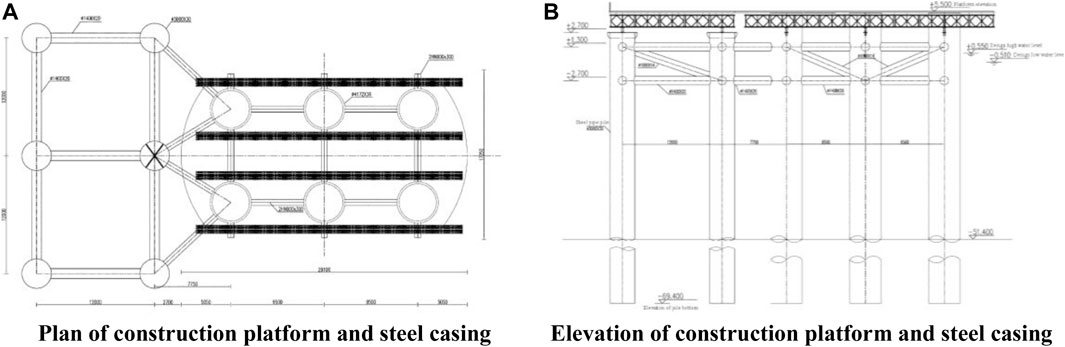
FIGURE 4. Geometric parameters of construction platform and steel casing. (A) Plan of construction platform and steel casing. (B) Elevation of construction platform and steel casing.
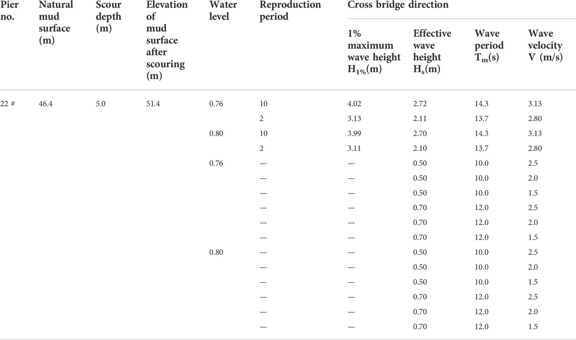
TABLE 1. Wave and current characteristics (Construction platform + steel casing).
According to the tidal parameters and site conditions of the study area, an indoor model test was designed to measure the horizontal wave flow force (moment) of typical piers under the action of waves and current for various forms of main pier foundation and steel trestle structure, as well as the wave flow force of steel trestle pier and bridge deck.
The experiment is conducted in the wave pool, which is 52 m long, 17.5 m wide, and 1.2 m deep. One end of the harbor pool is equipped with a gentle slope for de-wave, while the other end is equipped with an MTS irregular wavemaker that generates waves by computer control of associated factors. The wave-making device is capable of producing both regular and irregular waves as needed. 10 high-flow submersible pumps were installed in the pool to simulate the flow conditions in the same direction as a wave or at an angle of 45°. The arrangement of harbor basin with waves and current moving in the same direction is shown in Figure 5.
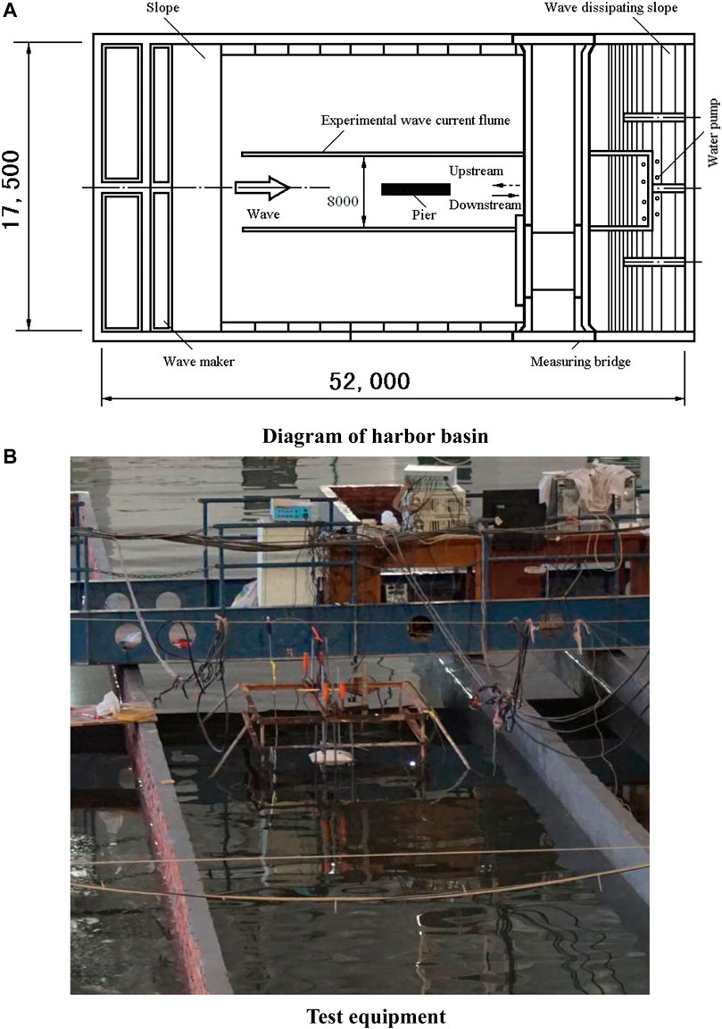
FIGURE 5. Diagram and test equipment of wave and harbor basin. (A) Diagram of harbor basin. (B) Test equipment.
According to Wave Model Test Regulation (JTJ/T 234-2001JTJ/T 234-2001), the test adopts a normal model developed in accordance with the Froude number similarity law, and the geometric scale was set as 1:70. The physical scale is shown in Table 2.
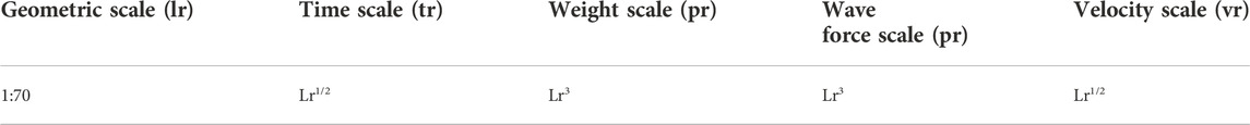
TABLE 2. Model scale.
In the model, the bridge pier, construction platform, pile foundation and other parts of the structure are made according to the geometric scale of 1:70, and the model is geometrically comparable to the prototype. Each part of the structure is simulated according to the rigid structure, using wood materials.
Primarily irregular waves were utilized in the experiment. The wave height, wave period, and other physical parameters in the model were determined according to the gravity similarity criterion. The characteristic wave elements were input into the computer to generate wave-making signals. Through the controller software and the electric rotary table connected with the structure model, the wave maker is controlled to generate the corresponding irregular wave sequence, so as to achieve the wave current force test under different wave direction angles.
The current making system consists of flow making pump, flow equalizing box, flow making inlet and outlet, return pipeline and measurement and control system. The wave making system is composed of wave maker, wave attenuation system and measurement and control system, which can make regular and irregular waves. The current generation system can work together with the wave generation system to achieve simultaneous wave generation and current generation.
The number of regular waves was greater than 20, and the number of irregular waves was greater than 120 in per set of tests, and each set of tests was repeated three times. In the model test, the error between the simulated and measured wave height and period was kept within ±2%. The wave velocity in the model was also determined by the gravity similarity criterion.
In the experiment, the designed water flow is initially simulated in the wave harbor pond, followed by the simulation of the given wave elements based on the existing water flow. The bridge foundation model is then positioned, and the wave water flow test is conducted. Type CBY-II wave altimeter (Figure 6) was used for wave element measurement, and propeller current meter was used to monitor water flow rate.

FIGURE 6. Type CBY-Ⅱwave height measurement and control system.
For the combination of different bridge foundation, wave, current, water level, and seabed elevation conditions, the Type LMA-A-10N-P total force (tension pressure) sensor is used to measure the horizontal force and vertical force of the bridge foundation structure when subjected to the joint action of wave and current. The wave force data is automatically collected by a computer, and the measurement outcomes are analyzed and processed by computer programs.
When measuring the total force, it is ensured that the structure is not susceptible to external forces other than the wave’s action with the total force sensor. The total force transducer is fixed with an iron frame and a metal screw (as depicted in Figure 7), and its sampling frequency is 125 Hz. It is used to measure the current pressure of large-diameter steel casing cylinders and construction platform piles, respectively.
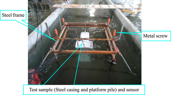
FIGURE 7. Test model and sensor installation.
When applying for large-diameter steel casing, it is necessary to first set up a construction platform and then utilize the starting platform to erect large-diameter steel casing. Therefore, it is required to test the force of platform piles and steel casings separately. Several examples, including a single platform pile, a single steel casing, three platform piles, six platform piles, and construction platform + steel casing as a whole are studied, and the water flow and wave force of the model are evaluated.
The wave current load tests are carried out on a single platform pile and steel casing. According to the field monitoring data, the wave parameters in the operation window are selected as shown in Table 3.
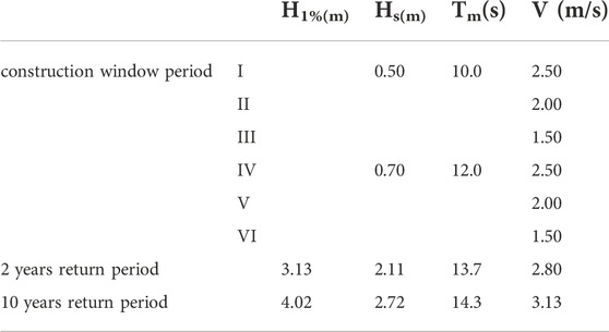
TABLE 3. Wave and current parameters.
When the water depth increases from 30 m to 55 m step by step, a single platform pile and steel casing are tested under the wave and current force. The test model is shown in Figure 8A, and the test results are shown in Figure 9.
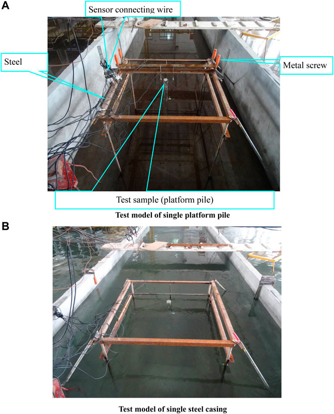
FIGURE 8. Test model of wave and current forces. (A) Test model of single platform pile. (B) Test model of single steel casing.
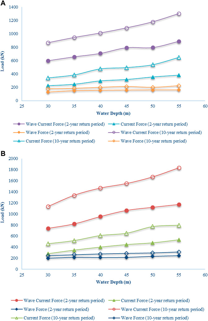
FIGURE 9. Curve of wave and current loads vary with water depth. (A) Loads in single platform pile. (B) Loads in single steel casing.
From the test results, it can be seen that under the same current and wave parameters, the water depth greater, the wave and current load on single pile and steel casing larger. At the same time, it is indicated that the combined force of wave and current is far greater than the sum of wave force and current force, with a maximum difference of 70%. The reason is that when the wave speed is greater than the current speed, part of the wave energy will be transferred to the current, which will increase the speed of the current. In the case of small amplitude waves, the force generated by waves is less than that generated by currents with the same energy, so the wave current force will be greater than the sum of current force and wave force (Liu, 2012).
Generally, when the current velocity is close to or greater than the wave velocity, the linear superposition value of wave force and current force cannot be used for the calculation of maximum wave current force, and the coupling effect between wave and current must be considered. In Code for sea port hydrology (JTS144-2010), the superposition method is used to calculate the wave current forces of small diameter cylinders and large diameter cylinders with large relative water depth under weak coupling conditions, without considering the interaction between waves and currents. However, in practical engineering calculation, due to the vague definition of weak coupling concept and the lack of calculation method of wave current force under strong coupling, it is necessary to determine the wave current force of bridge foundation through special physical model test during bridge foundation structure design.
According to Figure 9, it is found that the wave current force increases slightly with the increase of water depth, almost unchanged, and the current force and wave current combined force increase linearly with the depth. Under the conditions of 2-year return period and 10-year return period, the wave current force on the single pile is close, and the difference between the current force and the wave current combined force is obvious.
After the completion of the first pile on the construction platform, it is in the state of single pile, and the stability of single pile must meet the requirements. In order to find the appropriate construction window period, the stability of single pile under different wave and flow conditions should be verified. To test the wave and current forces of a single pile at the design water level of 0.55 m, the wave and current test model of the single platform pile is shown in Figure 8B, and the test findings of wave and current forces are shown in Table 4.
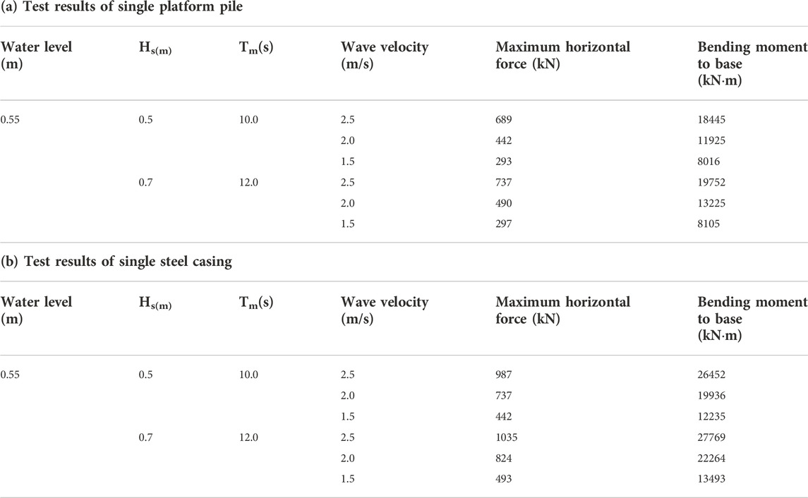
TABLE 4. Test results of wave and current forces of 22# Pier.
The experimental results indicate that under the conditions of effective wave height Hs = 0.5 m and water flow velocity is 2.5 m/s, the wave and current force of the single platform pile of the 22# main pier are maximized, with the maximum horizontal force is 689 kN, and the corresponding bending moment is 18445 kN*m. Under the condition that the effective wave height Hs = 0.7 m, when the water flow velocity is 2.5 m/s, the single platform pile of the 22# main pier is influenced by the wave and the water flow force reaches its maximum, the maximum horizontal force is 737 kN, and the corresponding bending moment is 19752 kN*m.
Under the condition that the effective wave height Hs = 0.5 m and the water flow velocity is 2.5 m/s, the single initial platform pile of the 22# main pier is impacted by waves and the water flow force reaches its maximum, the maximum horizontal force is 987 kN, and the corresponding bending moment is 26452 kN*m. Under the condition that the effective wave height Hs = 0.7 m, also when the water flow velocity is 2.5 m/s, the single initial platform pile of the 22# main pier is impacted by waves and the water flow force reaches its maximum, the maximum horizontal force is 1035 kN, and the corresponding bending moment is 27769 kN*m.
Draw the relationship curve between the maximum horizontal force and wave velocity as shown in Figure 10. It can be found from the figure that since the diameter of the platform pile is relatively small, the overall horizontal force is smaller than that of the steel casing. In the cases of Hs = 0.5 m, Tm = 10 s, and Hs = 0.7 m, Tm = 12 s, the maximum horizontal force and the bending moment to base approach linear as the flow rate rises. When the flow rate is low, the force difference of the platform pile is small, and as the flow rate grows, the horizontal force difference gradually increases, while the difference in the force of the steel casing is more obvious in both cases, with a difference of about 50–90 kN.
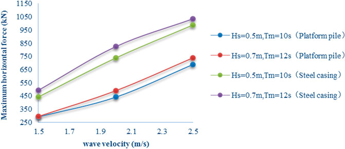
FIGURE 10. Relationship between maximum horizontal force and wave velocity.
In order to measure the distribution of the wave flow force along the vertical direction of the single platform pile and the steel casing, and to investigate the horizontal force and bending moment of the pile body during the wave-flow coupling action, the pressure sensor is arranged vertically on the platform pile and the steel casing respectively, as depicted in Figure 11. 1# Pressure sensor is positioned at the level, followed by a pressure sensor every 0.8 m, for a total of 6 measurement sites. During the test, 0.76 m of the 100-year return period high water level was selected to evaluate the horizontal pressure under the action of wave and current of 2-year return period and 10-year return period, respectively.
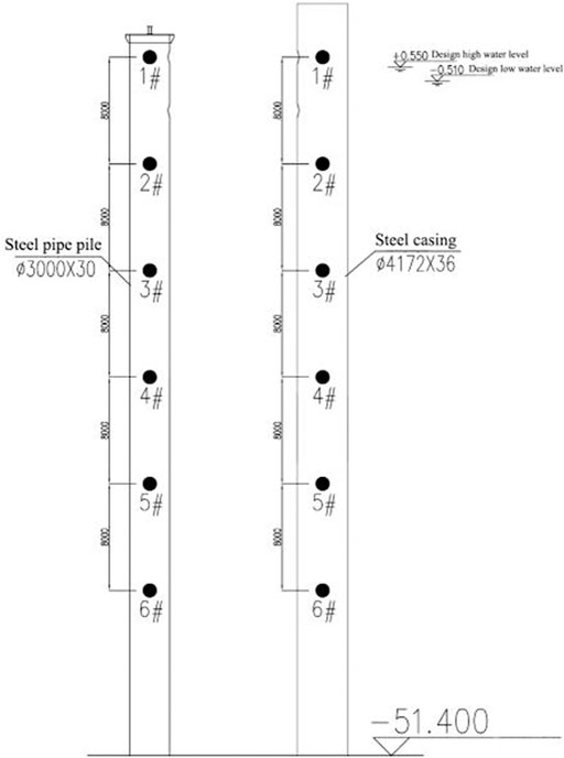
FIGURE 11. Point layout of pressure monitoring in 22# pier single platform pile and steel casing.
The test results are shown in Figure 12. Under the effect of 2-year return period wave and current, the horizontal pressure of a single platform pile and steel casing is basically close, and gradually increases along the pile body from bottom to top, and the pressure at the top reaches 17 kPa. Under the action of 10-year return period wave and current, the horizontal pressure of a single platform pile and a steel casing also increases gradually from the bottom to the top, but the values are distinct. The horizontal pressure of platform pile is significantly less than that of steel casing. The pressure of the bottom 6# monitoring point is 14.1 kPa and 16.5 kPa, respectively, at an elevation of −1.9 to −0.3 m, the horizontal pressure difference between the two gradually increases, with a maximum difference of about 6.3 kpa. At the top of the pile, the pressure between the two is relatively close, about 23 kPa.
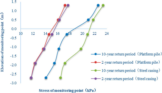
FIGURE 12. Distribution of the horizontal pressure on platform pile and steel casing along the vertical direction.
In order to study the changes in wave and current forces of platform pile and steel casing at the 22# main pier construction stage, the following tests were conducted: 1) Three platform piles are connected as a whole; 2) Six platform piles are connected as a whole; 3) The construction platform + steel cylinder as a whole, and the action of wave and current forces in the above three cases, the test device is depicted in Figure 13. Due to the short duration of the above working conditions (1) and (2), only the factors of 2-year return period are selected for testing. The factors of 2-year return period and 10-year return period are selected for the test in the above conditions (3). During the test, typical pile locations are selected to measure wave current load. The schematic diagram of pile locations is shown in Figure 14. The results of wave current force test are shown in Table 5.
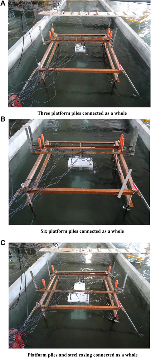
FIGURE 13. Test model of wave and current forces with. (A) Three platform piles connected as a whole. (B) Six platform piles connected as a whole. (C) Platform piles and steel casing connected as a whole.
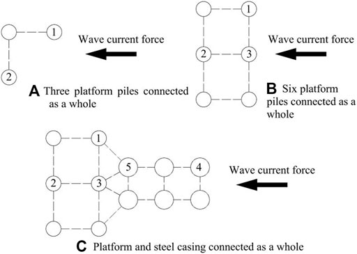
FIGURE 14. Schematic diagram of pile location for measuring wave current loads. (A) Three platforms piles connected as a whole. (B) Six platforms piles connected as a whole. (C) Platform and steel casing connected as a whole.
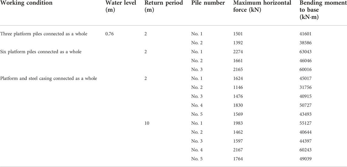
TABLE 5. Test results of wave and current forces on typical piles.
Under the condition of 100-year return period high water level+2 years return period wave and current, the maximum horizontal force is 1501 and 1392 kN respectively, which are measured at pile No.1 and pile No.2 in the structure of three platform piles connected as a whole. Since the connection between pile No.1 and pile No.2 is at a certain angle with the wave direction, there is no protective effect from pile 1 to pile 2, and the maximum horizontal force suffered by pile No.2 is close to that of pile No.1.
In the structure of six platform piles connected as a whole, the maximum horizontal force measured at pile No.1 is 2274 kN, the maximum horizontal force measured at pile No.2 is 1661 kN, and the maximum horizontal force measured at pile No.3 is 2165 kN, indicating that the front pile has a strong protective effect on the rear pile, so the maximum horizontal force suffered by pile No.2 is low.
After the construction platform and the steel pile casing are integrated, under the conditions of 100-year return period high water level +2 years return period wave and current, the maximum horizontal force on pile No.4 reaches 1830 kN, the maximum horizontal force on pile No.1 reaches 1624 kN, and pile No.2, No.3 and No.5 are protected by the front piles, so the horizontal force is small. Under the condition of 100-year return period high water level +10 years return period wave and current, the maximum horizontal force of pile No.4 is 2167 kN, and the maximum horizontal force of pile No.2 is 1462 kN, it is about 33% lower than that of the front row piles.
The force and bending moment of the whole structure are shown in Figure 15. Under the condition of 100-year return period water level + 2-year return period wave and current, with the construction of platform pile and steel casing, the pile body is subjected to increasing horizontal thrust and bending moment, and the growth rate of bending moment is slightly higher than that of horizontal force. Under the conditions of 10-year return period wave and current, the horizontal force and horizontal bending moment of the entire structure of the construction platform + steel casing are approximately 1.2 times that of the 2-year return period wave and current conditions.
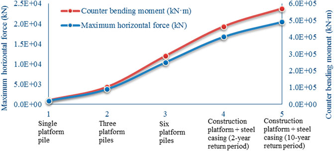
FIGURE 15. Maximum horizontal force and bending moment of the overall structure in different conditions.
Based on the Malé—Airport Island Bridge project of Maldives, the physical model tests of pile foundation subjected to wave and current were conducted to test the magnitude and distribution of wave and current force of platform pile and steel casing under varying conditions. The following conclusions were obtained:
1) Under the same effective wave height and wave period, as the increase of wave velocity, the maximum horizontal force and the bending moment against the bottom of the platform pile and steel casing increase linearly. For the same current and wave parameters, when the water depth is greater, the wave and current force subjected by the single pile and steel casing also increases, and the combined wave current force is greater than the sum of wave force and current force, with a maximum difference of 70%.
2) Under the action of 2-year return period wave and current, the horizontal pressure of a single platform pile and a steel casing increases linearly with the increase of height; under the action of 10-year return period wave and current, the difference of horizontal pressure between a single platform pile and a steel casing is pronounced and nonlinear.
3) In the pile group foundation, the front row piles have obvious protective effect on the rear row piles, and the wave current load on the rear row piles will obviously smaller than that on the front row piles. Under the conditions of 10-year return period wave and current, the horizontal force and horizontal bending moment of the entire structure of the construction platform + steel casing are approximately 1.2 times that of the 2-year return period wave and current conditions.
The original contributions presented in the study are included in the article/supplementary material, further inquiries can be directed to the corresponding author.
LL: Laboratory test, data analysis. LY: Drafting the manuscript, reviewing and editing. X-FX: Field investigation, data acquisition.
This work was supported by the Major project of CCCC Second Navigation Bureau (EHYF-2018-A-07–004); Natural Science Foundation of Jiangsu Higher Education Institutions of China (19KJD410001, 19KJD560001), Campus-level research projects of Changzhou Vocational Institute of Engineering: 11130300121008.
Author X-FX is employed by The Third Engineering Co., Ltd. of CCCC Second Navigation Bureau.
The remaining authors declare that the research was conducted in the absence of any commercial or financial relationships that could be construed as a potential conflict of interest.
The authors declare that this study received funding from CCCC Second Harbor Engineering Company Ltd. The funder had the following involvement in the study: model test and data collection.
All claims expressed in this article are solely those of the authors and do not necessarily represent those of their affiliated organizations, or those of the publisher, the editors and the reviewers. Any product that may be evaluated in this article, or claim that may be made by its manufacturer, is not guaranteed or endorsed by the publisher.
Chen, L. B., Wu, W. B., Liu, H., Li, J. X., Newson, T., and Naggar, M. H. (2022). Analytical solution for kinematic response of offshore piles under vertically propagating S-waves. Ocean. Eng. 262, 112018. doi:10.1016/j.oceaneng.2022.112018
Chen, X. (2015). Wind wave coupling test and wave force study on viaduct pier of sea-crossing bridge. Harbin Inst. Technol.. (Master Degree Thesis) doi:10.7666/d.D756193
Dai, S. M., and Wei, K. (2021). Wave current force analysis of bridge group pile foundation considering wave tide current correlation. (eds). Proceedings of the 30th. Natl. Acad. Conf. Struct. Eng. Vol. II, 68–71. doi:10.26914/c.cnkihy.2021.019031
Deng, S. S. (2021). Wave current force analysis of offshore engineering pier structure. Sichuan Architecture 41, 134–137. doi:10.3969/j.issn.1007-8983.2021.05.044
Hu, Y., Lei, L. P., and Yang, J. X. (2012). Isolation of human and mouse neutrophils ex vivo and in vitro. Methods Mol. Biol. 33, 101–113. doi:10.1007/978-1-61779-527-5_7
Huang, H. D., and Yu, X. D. (2009). Analysis and research on wave current force of jintang bridge. High. Way 01, 127–129.
JTJ/T 234-2001 (2001). Wave model test regulation (JTJ/T 234-2001). Beijing: People's Communications Press.
Li, J. (2016). Study on wave-current force characteristics of single pile and pile group structure. (Master Degree Thesis). Southwest Jiaotong University Chengdu. doi:10.27414/d.cnki.gxnju.2019.000368
Li, L. C., Liu, X., Liu, H., Wu, W. B., Lehane, B. M., Jiang, G. S., et al. (2022a). Experimental and numerical study on the static lateral performance of monopile and hybrid pile foundation. Ocean. Eng. 255, 111461. doi:10.1016/j.oceaneng.2022.111461
Li, L. C., Zheng, M. Y., Liu, X., Wu, W. B., Liu, H., Naggar, M. H., et al. (2022b). Numerical analysis of the cyclic loading behavior of monopile and hybrid pile foundation. Comput. Geotechnics 144, 104635. doi:10.1016/j.compgeo.2022.104635
Liu, L. (2012). Research on computing method of wave-current force on sea-crossing bridge substructures. (Doctor Degree Dissertation). Chengdu: Southwest Jiaotong University.
Maccamy, R. C., and Fuchs, R. A. (1954). Study on the anisotropy and anisotropy of the mehr mohr. U. S. Army Corps Eng. Beach Eros. Board 69, 75–86.
Ministry of Transport, PRC (2016). Code of hydrology for Harbour and Waterway (JTS 145-2015). Beijing: People's Communications Press. doi:10.1007/BF00250932
Morison, J. R., Johnson, J. W., and Schaaf, S. A. (1950). The force exerted by surface waves on piles. J. Petroleum Technol. 05, 149–154. doi:10.2118/950149-G
Sun, T. T., Wang, S. P., Pan, J. N., Wang, D. T., and Liu, Q. J. (2019). Study on wave-current force for pile foundation of sea-crossing bridge considering local scouring. Adv. Water Sci. 30, 863–871. doi:10.14042/j.cnki.32.1309.2019.06.010
Wang, Y., Wang, S. Q., and Wang, K. P. (2021). Numerical simulation of the characteristics of wave-current forces on a horizontal cylinder. Ship Sci. Technol. 21, 27–32. doi:10.3404/j.issn.1672-7649.2021.11.005
Zhang, H., Liu, Q. J., and Wang, D. T. (2018). Study on wave force calculation of large-scale structures. Waterw. Port 39, 151–156. doi:10.3969/j.issn.1005-8443.2018.02.005
Zhang, Y. P., Naggar, M. H., Wu, W. B., Wang, Z. Q., Yang, X. Y., and Jiang, G. S. (2022a). Dynamic torsional impedance of large-diameter pipe pile for offshore engineering: 3D analytical solution. Appl. Math. Model. 111, 664–680. doi:10.1016/j.apm.2022.07.017
Zhang, Y. P., Wang, Z. Q., Naggar, M. H., Wu, W. B., Wang, L. X., and Jiang, G. S. (2022b). Three-dimensional wave propagation in a solid pile during torsional low strain integrity test. Int. J. Numer. Anal. Methods Geomech. 46, 2398–2411. doi:10.1002/nag.3389
Zhou, W. B., Xu, Z. E., and Yu, X. H. (2015). Study on wave force calculation of yueqingwan bridge foundation. Highw. Traffic Technol. 4, 80–86. doi:10.13607/j.cnki.gljt.2015.04.017
Keywords: bridge foundation, steel casing, wave current force, model test, pile foundation
Citation: Li L, Yue L and Xing X-F (2023) Wave current force test of deep water foundation of bridge in marine environment. Front. Earth Sci. 10:1053190. doi: 10.3389/feart.2022.1053190
Received: 25 September 2022; Accepted: 02 November 2022;
Published: 13 January 2023.
Edited by:
Tianshou Ma, Southwest Petroleum University, ChinaReviewed by:
Ahmed Reda, Curtin University, AustraliaCopyright © 2023 Li, Yue and Xing. This is an open-access article distributed under the terms of the Creative Commons Attribution License (CC BY). The use, distribution or reproduction in other forums is permitted, provided the original author(s) and the copyright owner(s) are credited and that the original publication in this journal is cited, in accordance with accepted academic practice. No use, distribution or reproduction is permitted which does not comply with these terms.
*Correspondence: Ling Yue, NzMxNTA2ODgwQHFxLmNvbQ==
Disclaimer: All claims expressed in this article are solely those of the authors and do not necessarily represent those of their affiliated organizations, or those of the publisher, the editors and the reviewers. Any product that may be evaluated in this article or claim that may be made by its manufacturer is not guaranteed or endorsed by the publisher.
Research integrity at Frontiers
Learn more about the work of our research integrity team to safeguard the quality of each article we publish.