 Shuyin Ma
 Sheng Xue1,5
 Cheng Pan
94% of researchers rate our articles as excellent or good
Learn more about the work of our research integrity team to safeguard the quality of each article we publish.
Find out more
ORIGINAL RESEARCH article
Front. Earth Sci., 13 January 2023
Sec. Geohazards and Georisks
Volume 10 - 2022 | https://doi.org/10.3389/feart.2022.1051639
This article is part of the Research TopicGeological Disasters in Deep Engineering: Mechanism, Warning, and Risk Mitigation, volume IIView all 11 articles
To study the fatigue failure of an intermittent jointed rock mass under repeated stress waves, numerical models of jointed rock masses with different joint angles were created using Autodyne software, and crack propagation behavior was simulated using the Drucker–Prager strength model and cumulative damage failure criteria. In this numerical simulation, the influence of stress wave amplitude and the mode of disturbance on fatigue failure of the rock mass were analyzed. The simulation results showed a significant difference between the failure process of jointed rock masses subjected to repeated stress waves and those exposed to a single stress wave, including crack initiation locations, propagation paths, and rock mass failure patterns. With increasing angles of inclination, the fatigue life of the rock mass first decreased and then increased under repeated stress waves. As the joint inclination angle, β, increased from 20° to 50°, it had a significant influence on the fatigue life of the rock mass, which decreased rapidly with increases in β. The variation in the disturbance form (the change in amplitude of the stress waves from small to large, or from large to small) did not affect the final macro failure pattern of the rock mass; but the extent of damage to the rock mass was affected.
Different sizes of fractures, joints, beddings, and other discontinuous surfaces exist universally in natural rock masses. These discontinuous surfaces influence the mechanical properties and control the stability of a rock mass. Many geotechnical engineering tests demonstrated that the propagation and connection of joint fissures in a rock mass under an external load resulted in the instability and failure of geotechnical engineering (Tang et al., 2022). Many scholars have discussed the initiation, propagation, and evolution of cracks into macro-cracks through physical tests (Lin et al., 2000; Sagong and Bobet, 2002; Prudencio and van Sint Jan, 2007; Yang et al., 2019; Haeri et al., 2020; Wang M et al., 2020) and numerical modeling (Vergara et al., 2016; Wang and Tian, 2018; Wang X et al., 2020; Li et al., 2022; Yuan et al., 2022; Zou et al., 2022). Using physical tests, Lin et al. (2000) determined the influences of joint distribution, joint length, and rock bridge length in a jointed rock mass on connection modes, failure modes, and peak strength. They found that the number of joints, joint length, rock bridge length, and side pressure could significantly influence the connection modes, failure modes, and peak strength of a jointed rock mass. Sagong and Bobet (2002) conducted a comparative study on the connection modes of multi-fracture rock mass specimens and double-fracture rock mass specimens under uniaxial compression conditions. They discovered that the failure mode of a multi-fracture rock mass was similar to that of a double-fracture rock mass and identified nine double-fracture connection modes. Prudencio and Van Sint Jan (2007) carried out a biaxial compression test on discontinuous joint specimens formulated with cement mortar and summarized four failure modes of discontinuous jointed rock masses, namely, plane failure, block rotational failure, stepwise failure, and mixed failure. Haeri et al. (2020) conducted uniaxial compression tests to investigate the effect of joint number and angle on both compression behavior and joint tensile strength.
Recently, numerical software, such as UDEC (Pan et al., 2021; Li et al., 2022), PFC (Wang X et al., 2020; Yuan et al., 2022), and Autodyn (Li and Wong 2014; Zhao et al., 2020; Zou et al., 2022), were extensively compared as methods to simulate the crack propagation process. Compared with physical tests, numerical simulations can more easily obtain the mechanical information of crack initiation and propagation. For example, Li and Wong (2014) found 11 connection modes of double-fracture rock masses under uniaxial loading by using the nonlinear dynamic software, Autodyn. These connection modes were divided into tensile, shear, and mixed tensile-shear connection modes according to the mechanism of crack formation. Studies by Zhao et al. (2020) and Zou et al. (2022) also demonstrated that the combined use of the Drucker–Prager (DP) strength model and cumulative damage (CD) failure criteria could describe the macroscopic inelastic behavior of geotechnical materials and the evolution of CD-induced macro-cracks. It is worth noting that most existing research focused on the failure behavior of a jointed rock mass under static loading or single-impact loading.
As the literature shows, drilling and blasting are still the main methods of tunnel excavation (Pan et al., 2022). However, the cyclical footage of 3–5 m is often used during tunneling, indicating that the surrounding rocks within this range were also disturbed by multiple blasting excavations (Ji et al., 2021a, b). Although a single disturbance is insufficient to cause the instability of a rock mass, multiple disturbances can cause progressive failure of discontinuous jointed rock masses through the cumulative effects of repeated damage. These disturbances can lower bearing capacity and stability, thereby accelerating failure. Therefore, studying the fatigue failure process of discontinuous jointed rock masses under the action of repeated stress waves has practical significance for the long-term qualitative analysis of rock mass engineering. Based on this information, the fatigue failure process of a discontinuous jointed rock mass with different incidence angles under the action of repeated stress waves was investigated by using the DPCD model and Autodyn, and compared with that occurring under single impact loading. The influence of stress wave amplitudes and disturbance mode on the fatigue failure process of a discontinuous jointed rock mass was discussed.
The material model in Autodyn is mainly composed of state equation, strength model, and failure criteria.
The state equation belongs to a problem of small deformation dynamics because the stress wave amplitude in the simulation is small. Therefore, the state equation of the jointed rock mass can be described by the linear state equation (Zhao et al., 2020):
where p is the pressure, k is the bulk modulus,
A piecewise linear DP strength model was selected as the rock strength model (Li and Wong 2014). This model is applicable to granular materials, such as soils, rocks, and concretes and can accurately describe the cracking phenomena of materials. By defining the pressure–yield strength points, it was shown that the yield strength increased with hydrostatic pressure after giving consideration to compression (Figure 1). Using a scanning electron microscope, Wong and Einstein (2009a) observed that macro-cracks produced in marble under compression conditions were formed by the initiation, propagation, and connection of micro-cracks. Therefore, the initiation of macro-cracks is a cumulative process rather than the result of a single unexpected event. Thus, the CD failure criteria were chosen as the failure criteria in the numerical simulation. CD failure criteria pertain to the reduction in strength during the progressive failure process of materials by defining the damage factor, D, which is related to the deformation of materials. Its value is zero when the effective plastic strain (EPS) is smaller than a certain value (EPS1). When EPS is higher than EPS1, D increases linearly with the strains to a maximum Dmax (<1). At this moment, a corresponding effective plastic strain (EPS2) exists (Figure 2). D is expressed as (Li and Wong 2012)

FIGURE 1. Piecewise linear Drucker–Prager strength criteria (Li and Wong, 2014).
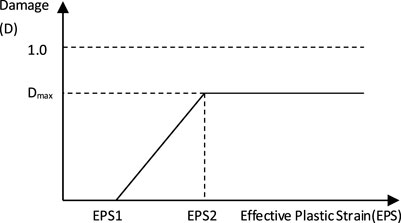
FIGURE 2. CD-plastic effective strain curve (Li and Wong, 2012).
After applying the calculation, the current value of D was used to modify the bulk modulus (k), shear modulus (G), and yield strength (Y) of materials. According to Li and Wong (2012), materials still retain some residual strength in the compression process when they reach maximum damage, but they have no residual strength in the tensile process. Hence, the reduction in Y involves two conditions. When the hydrostatic pressure is positive,
When the hydrostatic pressure is negative,
The bulk modulus and shear modulus are not influenced by compression. However, under tensile stress, the bulk modulus and shear modulus decrease to zero at the rate of
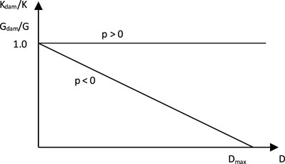
FIGURE 3. Damage curve of volume modulus and shear modulus.
The feasibility of the numerical simulation was verified according to the compression test results of uniaxial jointed rock masses (Wong and Einstein 2009b). The 150 mm × 75 mm two-dimensional plane model was applied in the numerical simulation, and the calculation model is shown in Figure 4. The model contains two parallel open joints. The lengths of the joints and the rock bridge were 2a = 12.7 mm and L = 12.7 mm, respectively. The angles between the rock bridge and the joint were α = 30° and β = 90°, respectively. During the simulation, loads were applied at the top and bottom of the specimens. The loading rate was controlled at 12.5 MPa/ms.

FIGURE 4. Schematic representation of the calculation model.
The numerical simulation results of the joint connection are shown in Figures 5A–C. The initiation points, propagation paths, and connection modes of cracks were easily observed, and the simulation results agreed well with the crack connection modes (Figure 5D), which are summarized according to test results by Wong and Einstein (2009b). On this basis, the DPCD model is feasible in simulating the failure process of a jointed rock mass.
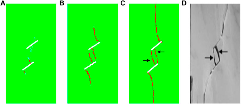
FIGURE 5. Comparison between numerical simulation and experimental results.
The failure process of a discontinuous jointed rock mass under different incidence angles was studied using the 150 mm × 75 mm two-dimensional plane model. Loads were applied at the top of the model and a fixed constraint was applied at the bottom. The geometrical parameters of the joint mainly included joint length (2a), length of rock bridge (L), angle of steps (γ), angle of joint (β), and joint spacing (d). The definitions of these parameters are shown in Figure 6. The joint geometric parameters involved in this model are listed in Table 1, and the joint geometry layout is shown in Figure 7.
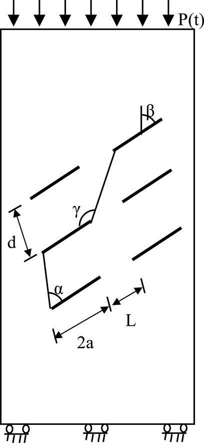
FIGURE 6. Schematic of joint geometrical parameters.
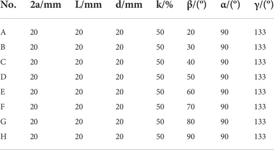
TABLE 1. Parameters for joint layout.
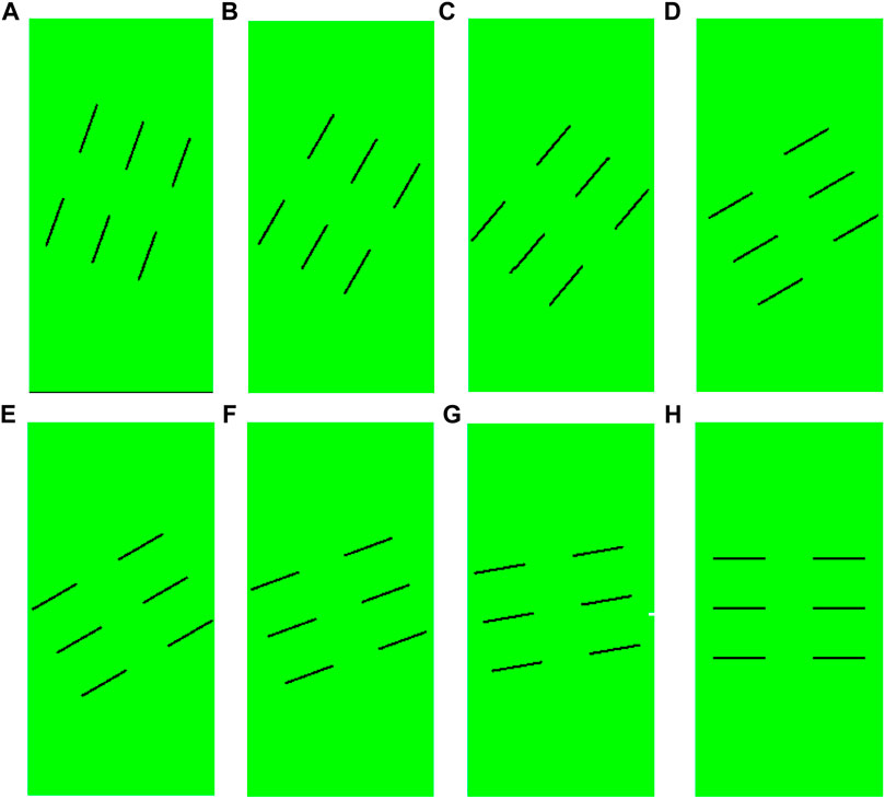
FIGURE 7. Joint geometry layout of the numerical model.
The action of repeated stress waves is different from ordinary cyclic loading. The dynamic stress field generated by the action of repeated stress waves is a pulsating stress field rather than an alternating stress field (Shao, 2005). During simulation, the time interval between two adjacent stress waves was set at t0 to prevent the influence of previous stress waves on the rock mass responses on follow-up. Hence, the action of repeated stress waves was simplified to repeated impact loading in Figure 8.
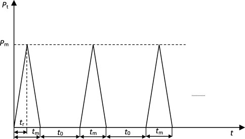
FIGURE 8. Mode of action of repeated stress waves.
The amplitude, the pressure rising time, and the action time under the influence of a single stress wave were set to 5 MPa, and tr = 100 μs, and tm = 200 μs, respectively. The failure processes of discontinuous jointed rock masses with different incidence angles under single stress wave are shown in Table 2. Clearly, the initiation positions of the cracks in the joints were controlled by the incidence angle, β. When β was <70°, the cracks began at the two ends of the joint. When β reached 70°, the cracks were initiated at points far away from the joint. The initiation positions of cracks on the upper and lower surfaces of the same joint were gradually approaching with the increase in the incidence angle of joints.
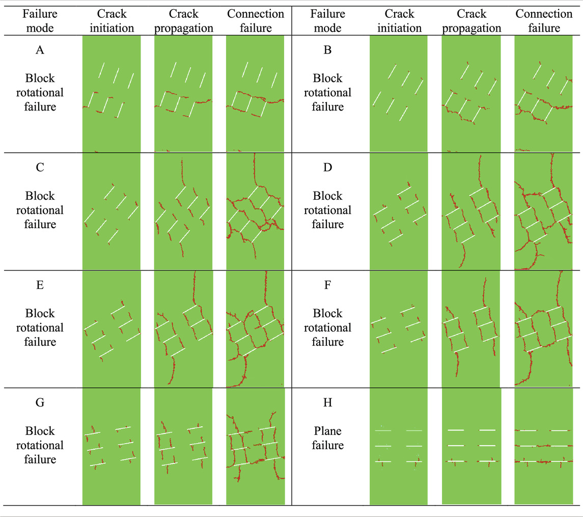
TABLE 2. Failure processes of jointed rock masses under single impact loading.
As the loading process continued, wing cracks continued to propagate (except at β = 90°), and the propagation paths of cracks were influenced by adjacent joints. When β = 20°, wing cracks propagated along the initiation direction continuously, but none was deflected toward the direction of major principal stress. This finding indicated that the influences of adjacent joints on wing cracks were weakened with the increase in the incidence angle of the joints. When β = 90°, the wing cracks produced secondary coplanar cracks rather than propagating continuously and were connected to adjacent collinear joints, ultimately causing plane failure. Plane failure refers to a failure mode wherein wing cracks began at joint ends, propagated under external loads, and connected with adjacent collinear joints. The failure surface presented a plane or approximate plane. Failure modes A–G were manifested as block rotational failures. Block rotational failure refers to a failure mode wherein wing cracks initiate at joint ends or surfaces, propagate under external loads, and connect with adjacent non-collinear joints to cut rock mass into numerous blocks that allow shear sliding or rotational displacement under external load.
The amplitude, the pressure rising time, the action time, and the time interval under the action of repeated stress waves were set to 1 MPa, tr = 100 μs, tm = 200 μs, and t0 = 2,800 μs, respectively. The failure processes of discontinuous jointed rock masses with different incidence angles under the action of repeated stress waves are shown in Figure 9. Cracks all initiated at the two ends of the joints under the action of repeated stress waves and changed with the variations of β. Moreover, the initiated cracks easily propagated toward the original initiation direction. The failure modes of the jointed rock mass with incidence angles other than β = 20°, 30°, and 90° all changed compared with those under the action of a single stress wave. Plane and step failures were the predominant modes under the action of repeated stress waves. Step failures resulted from connections between wing cracks and adjacent nonlinear joints in a stepwise distribution. In contrast, the block rotational failure was the major failure mode under the action of a single stress wave. The fatigue failure processes of a jointed rock mass under repeated stress waves, including initiation positions of cracks, propagation paths of cracks, and failure modes of rock mass, were significantly different from those resulting from a single stress wave. This result is related to the angle of incidence of the joints.
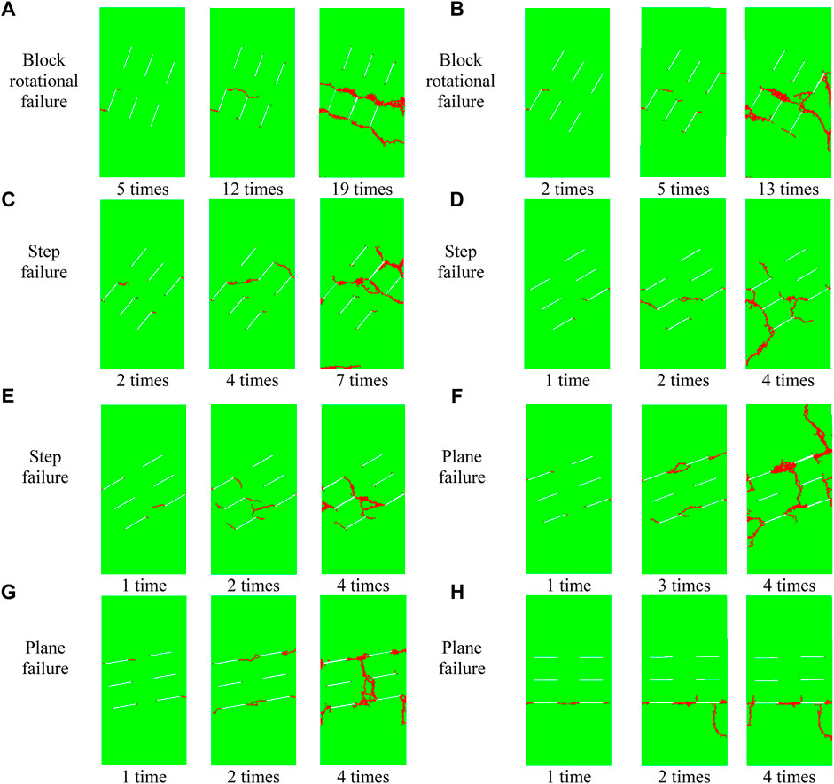
FIGURE 9. Failure process of a jointed rock mass under repeated impact loading.
The curve showing the relationship between the fatigue life of a discontinuous jointed rock mass (loading times, N, and incidence angle of joints, β) is shown in Figure 10. The fatigue life of a jointed rock mass presented a V-shaped variation trend with increasing incidence angle. When β was between 20° and 50°, the fatigue life of the rock mass was significantly influenced by the incidence angle of the joint and was significantly decreased with the increase of β. When β was between 50° and 90°, the fatigue life of the rock mass increased continuously with the incidence angle. When β was between 60° and 80°, the fatigue life of the rock mass was relatively stable and only slightly influenced by β.
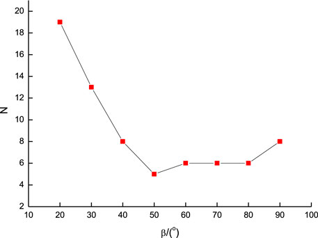
FIGURE 10. Loading times of a jointed rock mass with different stress wave incidence angles.
According to previous studies, a stress threshold exists for the fatigue failure of a rock mass. Under conditions of cyclic impacts, each stress event would intensify the internal damage to the rock mass only when its loading strength reached 80%–90% of static peak strength (Li et al., 2005). Thus, load amplitudes have important influences on the fatigue life of the rock mass. However, the mechanism of how loading amplitude affects the fatigue failure mode of a rock mass is still unclear and requires further investigation. In this study, a model with β = 50° was selected as the research subject to investigate the effects of repeated stress waves of different amplitude on the fatigue failure modes of a discontinuous jointed rock mass.
Figures 11A and B show the simulation results for stress wave amplitudes of 0.5 MPa and 2 MPa, respectively. When the stress wave amplitude was 0.5 MPa (Figure 11A) , short cracks were only seen initiating from the joint ends after three loading events. The wing cracks were connected to the adjacent non-collinear joints in a stepwise distribution after seven loading events. Wing cracks were generally straight, but there were local bifurcation phenomena, which ultimately led to step failure. Figure 11B shows that when the stress wave amplitude was increased to 2 MPa, wing cracks connected to adjacent non-collinear joints in stepwise distribution after only a single loading. The crack propagation path was relatively zigzag, and obvious bifurcation of wing cracks occurred after two loading times. The failure modes of a jointed rock mass were complex, with local X-shaped connections; hence, variations in stress wave amplitude could influence not only the fatigue life but also the failure mode of a jointed rock mass.
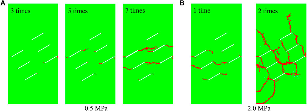
FIGURE 11. Failure process of a jointed rock mass with different loading magnitudes (β = 50°).
This study proved the importance of the critical stress value under the action of repeated stress waves. When the stress wave amplitude was higher than the threshold but smaller than the critical value, the jointed rock mass developed a single failure point under repeated stress waves. However, the failure modes of the rock mass were complicated by the continued increase in stress wave amplitude.
In a practical engineering situation, the disturbance intensity at the same position of a rock mass changes as the tunnel face is advanced forward; thus, the influence of disturbance modes on the failure modes of a jointed rock mass must be considered. A model with β = 50° was chosen as the research subject, and two disturbance modes were considered: (1) stress wave amplitude increased with a loading order of 0.5, 1, 1.5, and 2 MPa, and (2) stress wave amplitude decreased with a loading order of 2, 1.5, 1, and 0.5 MPa. Other conditions were fixed. The failure processes of a jointed rock mass under the two disturbance modes are shown in Figures 12A and B, respectively. Under disturbance mode 1 (Figure 12A), only extremely short cracks were initiated at the joint ends in the first two loadings because of the small amplitude. After three loading events, wing cracks propagated and connected with adjacent non-collinear joints in a stepwise distribution. As the loading increased, wing cracks were connected with adjacent non-collinear joints, and a trend of mixed failure occurred. Under disturbance mode 2 (Figure 12B), wing cracks were connected with adjacent non-collinear joints in a stepwise distribution after one loading event. Some adjacent non-collinear joints were connected after two loading times, with general mixed failure.
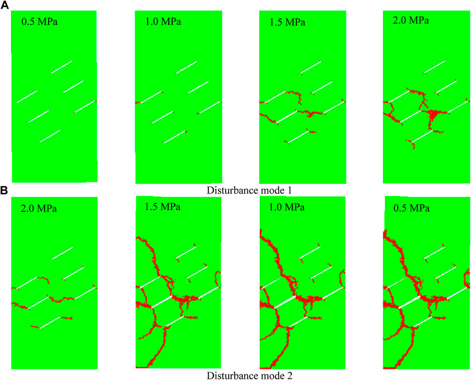
FIGURE 12. Failure process of jointed rock mass with different load modes (β = 50°).
By comparing the failure modes under the two disturbance modes, it is obvious that they were similar, but the failure degree of a rock mass under disturbance mode 2 was far higher than that under disturbance mode 1. This result occurred most likely because the different disturbance modes caused different initial damage to the rock mass. Given stronger initial damages, the rock mass could reach the peak failure point by absorbing less energy, and the degree of post-peak rock fracture was higher. Thus, the type of disturbance mode did not affect the final macroscopic failure mode of the rock mass, but it did influence the failure degree.
In this study, a numerical simulation analysis on the failure processes of discontinuous jointed rock masses was carried out using the Autodyn element software. Some major conclusions can be drawn as follows:
1) The fatigue failure modes of a jointed rock mass under repeated stress waves, including the initiation positions of cracks, propagation paths of cracks, and failure modes of rock masses, were significantly different from those under a single stress wave. The differences were influenced by the incidence angle of the joints.
2) The fatigue life of a rock mass as a function of increase in the incidence angle presents a V-shaped variation trend. When β was between 20° and 50°, the fatigue life of the rock mass was significantly influenced by the incidence angle of joints, and it decreased significantly with increasing β. When β was between 50° and 90°, the fatigue life of the rock mass increased continuously with the incidence angle.
3) The stress wave amplitude can influence not only the fatigue life but also the failure mode of a jointed rock mass. A critical stress value is under the influence of repeated stress waves. When the stress wave amplitude is higher than the threshold but smaller than the critical value, the jointed rock mass develops a single failure under repeated stress waves. However, the failure modes of rock mass become more complex with the continued increase in stress wave amplitude.
4) The different disturbance modes had no effect on the final macroscopic failure mode of the rock mass, but they did affect the failure degree of the rock mass. The failure degree of a jointed rock mass under the disturbance mode with decreasing stress wave amplitude was far higher than that under the disturbance mode with the increasing stress wave amplitude.
The datasets presented in this study can be found in online repositories. The names of the repository/repositories and accession number(s) can be found in the article/Supplementary Material.
SM contributed to the overall conception, writing, and data analysis of the article. SX reviewed the rationality of the overall conception of the article. CP carried out numerical simulation experiments.
This research was supported by the National Natural Science Foundation of China Key Project (51934007), the Regional Innovation and Development Joint Fund of the National Natural Science Foundation of China (U21A20110), the Key R&D Projects in Shandong Province (2019SDZY02), the Chongqing Municipal Technology Innovation and Application Development Special Key Project (cstc2019jscx-gksbX0076), and the Technological Innovation and Entrepreneurship Fund Special Project of Tiandi Technology Co., Ltd. (2022-2-TD-ZD008).
The authors would like to express sincere thanks to those researchers whose techniques have contributed to this research.
The authors declare that this study received funding from Tiandi Technology Co., Ltd. The funder was not involved in the study design, collection, analysis, interpretation of data, the writing of this article, or the decision to submit it for publication.
All claims expressed in this article are solely those of the authors and do not necessarily represent those of their affiliated organizations, or those of the publisher, the editors, and the reviewers. Any product that may be evaluated in this article, or claim that may be made by its manufacturer, is not guaranteed or endorsed by the publisher.
Haeri, H., Sarfarazi, V., Ebneabbasi, P., Nazari maram, A., Shahbazian, A., Fatehi Marji, M., et al. (2020). XFEM and experimental simulation of failure mechanism of non-persistent joints in mortar under compression. Constr. Build. Mater. 236, 117500. doi:10.1016/j.conbuildmat.2019.117500
Ji, L., Zhou, C., Lu, S., Jiang, N., and Gutierrez, M. (2021a). Numerical studies on the cumulative damage effects and safety criterion of a large cross-section tunnel induced by single and multiple full-scale blasting. Rock Mech. Rock Eng. 54 (12), 6393–6411. doi:10.1007/s00603-021-02630-9
Ji, L., Zhou, C., Lu, S., Jiang, N., and Li, H. (2021b). Modeling study of cumulative damage effects and safety criterion of surrounding rock under multiple full-face blasting of a large cross-section tunnel. Int. J. Rock Mech. Min. Sci. 147, 104882. doi:10.1016/j.ijrmms.2021.104882
Li, H. Q., and Wong, L. N. Y. (2014). Numerical study on coalescence of pre-existing flaw pairs in rock-like material. Rock Mech. Rock Eng. 47 (6), 2087–2105. doi:10.1007/s00603-013-0504-6
Li, H., and Wong, L. N. Y. (2012). Influence of flaw inclination angle and loading condition on crack initiation and propagation. Int. J. Solids Struct. 49 (18), 2482–2499. doi:10.1016/J.IJSOLSTR.2012.05.012
Li, X. B., Lok, T. S., and Zhao, J. (2005). Dynamic characteristics of granite subjected to intermediate loading rate. Rock Mech. Rock Eng. 38 (1), 21–39. doi:10.1007/s00603-004-0030-7
Li, X., Pan, C., Li, X., Shao, C., and Li, H. (2022). Application of a synthetic rock mass approach to the simulation of blasting-induced crack propagation and coalescence in deep fractured rock. Geomech. Geophys. Geo. Energy. Ge. Resour. 8 (2), 57. doi:10.1007/s40948-022-00376-4
Lin, P., Wong, R. H. C., Chau, K. T., and Tang, C. A. (2000). Multi-crack coalesence in rock-like material under uniaxial and biaxial loading. Key Eng. Mat. 187 PART 2, 809–814. doi:10.4028/www.scientific.net/kem.183-187.809
Pan, C., Li, X., Li, J., and Zhao, J. (2021). Numerical investigation of blast-induced fractures in granite: Insights from a hybrid LS-DYNA and UDEC grain-based discrete element method. Geomech. Geophys. Geo. Energy. Ge. Resour. 7 (2), 49. doi:10.1007/s40948-021-00253-6
Pan, C., Xie, L. X., Li, X., Liu, K., Gao, P. F., and Tian, L. G. (2022). Numerical investigation of effect of eccentric decoupled charge structure on blasting-induced rock damage. J. Cent. South Univ. 29 (2), 663–679. doi:10.1007/s11771-022-4947-3
Prudencio, M., and van Sint Jan, M. (2007). Strength and failure modes of rock mass models with non-persistent joints. Int. J. Rock Mech. Min. Sci. 44 (6), 890–902. doi:10.1016/j.ijrmms.2007.01.005
Sagong, M., and Bobet, A. (2002). Coalescence of multiple flaws in a rock-model material in uniaxial compression. Int. J. Rock Mech. Min. Sci. (1997). 39 (2), 229–241. doi:10.1016/s1365-1609(02)00027-8
Shao, P. (2005). Study on the dynamic effect of elastic wave in intermittently jointed rock mass. Xuzhou: China University of Mining and Technology Press.
Tang, X., Tao, S., Li, P., Rutqvist, J., Hu, M., and Sun, L. (2022). The propagation and interaction of cracks under freeze-thaw cycling in rock-like material. Int. J. Rock Mech. Min. Sci. 154, 105112. doi:10.1016/j.ijrmms.2022.105112
Vergara, M. R., van Sint Jan, M., and Lorig, L. (2016). Numerical model for the study of the strength and failure modes of rock containing non-persistent joints. Rock Mech. Rock Eng. 49 (4), 1211–1226. doi:10.1007/s00603-015-0824-9
Wang, X., and Tian, L. G. (2018). Mechanical and crack evolution characteristics of coal-rock under different fracture-hole conditions: A numerical study based on particle flow code. Environ. Earth Sci. 77 (8), 297. doi:10.1007/s12665-018-7486-3
Wang, M, M., Wan, W., and Zhao, Y. (2020). Experimental study on crack propagation and the coalescence of rock-like materials with two preexisting fissures under biaxial compression. Bull. Eng. Geol. Environ. 79, 3121–3144. doi:10.1007/s10064-020-01759-1/
Wang, X, X., Yuan, W., Yan, Y., and Zhang, X. (2020). Scale effect of mechanical properties of jointed rock mass: A numerical study based on particle flow code. Geomechanics Eng. 21 (3), 259–268. doi:10.12989/GAE.2020.21.3.259
Wong, L. N. Y., and Einstein, H. H. (2009a). Crack coalescence in molded gypsum and carrara marble: Part 1. Macroscopic observations and interpretation. Rock Mech. Rock Eng. 42 (3), 475–511. doi:10.1007/s00603-008-0002-4
Wong, L. N. Y., and Einstein, H. H. (2009b). Crack coalescence in molded gypsum and carrara marble: Part 2 - microscopic observations and interpretation. Rock Mech. Rock Eng. 42 (3), 513–545. doi:10.1007/s00603-008-0003-3
Yang, S. Q., Yin, P. F., Zhang, Y. C., Chen, M., Zhou, X. P., Jing, H. W., et al. (2019). Failure behavior and crack evolution mechanism of a non-persistent jointed rock mass containing a circular hole. Int. J. Rock Mech. Min. Sci. 114, 101–121. doi:10.1016/j.ijrmms.2018.12.017
Yuan, W., Wang, X., and Wang, X.-B. (2022). Numerical investigation on effect of confining pressure on the dynamic deformation of sandstone. Eur. J. Environ. Civ. Eng. 26 (9), 3744–3761. doi:10.1080/19648189.2020.1816217
Zhao, G., Liu, C., Pan, C., and Meng, X. (2020). Researches on crack propagation of the two filled noncoalescent coplanar flaws under the high strain rate loading by means of AUTODYN-based simulation. Geofluids 2020, 1–10. doi:10.1155/2020/8875734
Keywords: rock mechanics, stress wave, intermittent jointed rock mass, fatigue failure, numerical simulation
Citation: Ma S, Xue S and Pan C (2023) Numerical simulations of fatigue failure processes in intermittent jointed rock masses under the action of repeated stress waves. Front. Earth Sci. 10:1051639. doi: 10.3389/feart.2022.1051639
Received: 23 September 2022; Accepted: 01 November 2022;
Published: 13 January 2023.
Edited by:
Lijie Guo, Beijing Mining and Metallurgy Technology Group Co., Ltd., ChinaReviewed by:
Xiao Wang, Southeast University, ChinaCopyright © 2023 Ma, Xue and Pan. This is an open-access article distributed under the terms of the Creative Commons Attribution License (CC BY). The use, distribution or reproduction in other forums is permitted, provided the original author(s) and the copyright owner(s) are credited and that the original publication in this journal is cited, in accordance with accepted academic practice. No use, distribution or reproduction is permitted which does not comply with these terms.
*Correspondence: Shuyin Ma, NDAyMzYyMzI1QHFxLmNvbQ==
Disclaimer: All claims expressed in this article are solely those of the authors and do not necessarily represent those of their affiliated organizations, or those of the publisher, the editors and the reviewers. Any product that may be evaluated in this article or claim that may be made by its manufacturer is not guaranteed or endorsed by the publisher.
Research integrity at Frontiers
Learn more about the work of our research integrity team to safeguard the quality of each article we publish.