 Jian Hao
 Anfa Chen
 Xuelong Li
 Hua Bian
 Yongkui Shi1,2
95% of researchers rate our articles as excellent or good
Learn more about the work of our research integrity team to safeguard the quality of each article we publish.
Find out more
ORIGINAL RESEARCH article
Front. Earth Sci. , 11 November 2022
Sec. Economic Geology
Volume 10 - 2022 | https://doi.org/10.3389/feart.2022.1051245
This article is part of the Research Topic Exploration, Exploitation, and Utilization of Coal-Measure Gas into the Future: Volume II View all 17 articles
Strip coal pillars caused by strip mining are widely distributed in China. Over time, strip coal pillars are posing more potential hazards as their stability decreases; therefore, it becomes increasingly important to recover coal pillars without damaging the ground surface. In this paper, strip-filling and second-mining technique is adopted to probe into an optimal scheme for mine goafs. Construction waste was one type of the materials used for backfilling, which was taken to underground from the surface with a pumping system. Jisuo Coal Mine of Tengzhou, Shandong province was taken as the object of study. Through theoretical calculation and on-site survey, we set a re-mining scheme to control rock stratum stability, i.e., 8-m-wide backfilling for the first time and 4-m-wide backfilling for the second time; moreover, the ground pressure behavior and subsidence of working surface were monitored and a contour map of surface subsidence was thus mapped. In-situ practice indicated that the underground pressure from coal pillars was transmitted to the backfilling materials, the maximum normal stress of which was 5 MPa, so it was sufficient for the backfilling strip to support the weight of overlying strata; the maximum value of roof-to-floor convergence of backfilled mining face is 45 mm, the maximum surface subsidence 44mm, the maximum inclination value 0.65 mm/m, the maximum surface curvature 0.018 mm/m2, and the maximum horizontal deformation 0.16 mm/m. The filling body in the original goafs plays the role of “pier”. By the monitoring data of subsidence, its surface deformation value was less than that of buildings suffering from grade I damage, which verified the feasibility of strip-filling and second-mining scheme. The success in this technique provides reliable technical and theoretical support for mines with similar conditions.
Strip mining is an effective method for mining coal resources reserved under railways, rivers and buildings (Huang et al., 2014; Du et al., 2019a). For decades, China has mined an enormous amount of coal resources in the eastern and northern regions of China from coal mines with the above conditions. With such method, however, a large number of coal pillars are left underground (Ghasemi et al., 2014). Over the years, coal pillars have been exposed to the risk of instability caused by weathering and rheology, resulting in mine tremors and surface subsidence (An et al., 2016; Raffaldi et al., 2019; Sun D. Q. et al., 2021). In addition, some coal mines in eastern China hardly have any coal resources to recover. Given the current situation, it is of great significance in China not to disrupt the ecology and surrounding environment (Qian et al., 2007; Zou et al., 2018b; Hao et al., 2019; Zhou et al., 2022).
In the past few decades, filling and remining has developed rapidly and has been widely used in underground mines in China (Cao, 2017; Yan et al., 2018; Li et al., 2021; Wang et al., 2022). In this regard, relevant scholars first focused on filling materials (Guo et al., 2007; Mkadmi et al., 2014; Qu et al., 2017; Xuan and Xu, 2017; Zhu et al., 2018). (Mohamed and Li, 2017) presented a numerical study carried out to evaluate the stresses in backfilled stopes overlying, compared with the case of a single isolated backfilled stope, the numerical results show that the stress magnitudes in the overlying backfill are considerably increased due to the excavation of the underlying stope (Mohamed and Li, 2017). Zhu et al. (2020a) used the filling scheme to recover wide coal pillars, investigated the stability of coal pillars, the structural characteristics of the overlying strata and the paste filling technical parameters in coal pillar after strip mining through laboratory test (Zhu et al., 2020a), numerical simulation and physical simulation, and put forward a more feasible filling and remining scheme (Liu et al., 2017; Cao et al., 2018; Jiang et al., 2020; Shao et al., 2021). Luan et al. (2017) introduced a new technique for filling and remining thin coal seams, including the development of filling materials, the design and key technology of the filling system for thin seam working faces (Luan et al., 2017). Tuylu, (2022) studyed fly ash with four different chemical compositions (TFA, SFA, YFA, and CFA) was used as a cement substitute in CPB. By substituting fly ash with different chemical compositions in different proportions, CPB samples were created and their strength was elucidated according to 28, 56, and 90-day curing times (Tuylu, 2022). Sun Q. et al. (2021) used short-strip coal pillar recovery with cemented paste backfill (Sun Q. et al., 2021). They developed a paste filling recovery method for residual room coal pillars and investigated its performance through numerical simulation (Luan et al., 2017; Zhou D. W. et al., 2019; Mu et al., 2019; Liu et al., 2020; Sun Q. et al., 2021; Tuylu, 2022). Mamadou Fall et al. (2007) discussed the stress–strain behaviours of cemented paste backfill (CPB) subjected to uniaxial compression and conventional triaxial tests (Fall et al., 2007). In the mining process, in order to solve the problems of rock stratum movement and solid waste disposal, engineers, technicians and researchers have always adopted the filling and remining method. They have also studied the response of formation to partial backfilling and mining technique (Chen et al., 2010; Du et al., 2019b). It is stated that the partial use of C-Class fly ash instead of cement in paste backfill greatly increases the strength in long-term curing (Benzaazoua et al., 2002; Cihangir et al., 2015; Ercikdi and Yilmaz, 2019). Taking into account different geological conditions, Ning et al. (2021) studied the stress distribution on the floor boundary during open-pit mining and backfill mining above the confined aquifer (Ning et al., 2021). These two mining types were simplified as mechanical problems under different boundary conditions. The stress distribution and floor failure evolution in strip mining and filling replacement mining were studied with an elastic mechanics method (Sun and Wang, 2011; Chang et al., 2014; Sun et al., 2018).
Some scholars adopted FLAC3D numerical simulation to study the sensitivity of the main control factors of surface movement and deformation in strip filling and remining, which has important practical significance for protecting surface structure, reducing ecological damage and realizing green and sustainable development of coal mine (Zhang et al., 2016). Based on the limit equilibrium theory, Zhu et al. (2020) established the calculation formulas for the widths of the crushing zone, plastic zone and elastic zone of different types of composite supports, and proposed the design methods for the safety widths of different types of composite supports, providing a theoretical basis for the stability analysis of composite supports (Zhu et al., 2020b; Zou et al., 2020). Nevertheless, studies regarding the recovery of shallow narrow coal pillars have rarely been reported.
In order to increase the mine life and improve the recovery rate of resources, this paper takes the 16E104, 16E106, and 16E108 working faces of Jisuo Coal Mine as the engineering background, and puts forward and implements a coal pillar remining and disaster pre-control technology for strip goafs. Filling and remining is carried out with a filling material comprised of construction waste as the aggregate, a proprietary three-stage continuous concrete mixing device and a large domestic displacement concrete pump used as the filling power system. This technology allows the recovery of about 500 strip coal pillars with modest surface subsidence. Verification through underground mine pressure monitoring and surface settlement observation reveal that the strip filling bodies can work successfully in place of underground coal pillars without damaging the buildings or the environment, providing an effective method for recovering coal pillars. The strip filling and remining technology is effective in controlling the surface movement and deformation and protecting surface buildings. It also provides useful clues for other mining areas with similar geological and mining technical conditions.
Jisuo Coal Mine is located at the southern end of Wangchao exploration area of Tengbei coalfield. The mine field is of plain terrain with high population density. Coal under village accounts for more than 80% of the recoverable reserves of the mine. The length of the mine field is about 5.8 km. The average width is about 1.2 km, and the mine field area is about 7.0 km2. Figure 1 shows the location of the mine.
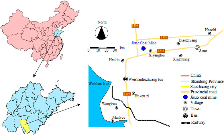
FIGURE 1. Mine location.
Since the 1990s, Jisuo Coal Mine has been operating for almost 20 years under the villages by means of strip mining. So far, 655 strips have been mined, and a total of 807,000 tons of coal resources have been recovered. However, 564 strip coal pillars as the support of the overlying strata are still left underground, resulting in a stagnant coal reserve of 717,000 tons. The untapped reserves under the village are about 5.61 million tons, as shown in Figure 2. With the depletion of recoverable reserves, the mine is facing the threat of closure and shutdown.
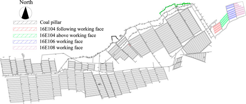
FIGURE 2. Distribution map of the remining pillars in Jisuo Coal Mine.
In order to investigate the feasibility of remining strip coal pillars, filling remining test was carried out on 16E104, 16E106, and 16E108 working faces. There are no buildings on the ground in this area. Surface subsidence was observed after backfilling to provide basis for the filling and remining of the other areas. The coal seam mined in the test working face is Coal 16, which has an average thickness of 1 m and a dip angle of 5°–10°. Its occurrence is stable or relatively stable, and its thickness variation is insignificant. The coal bed texture is simple and is a comparatively regular coal seam. The average vertical depth of mining is 120 m. The roof is limestone with a thickness of 5.3 m and the floor is mudstone with a thickness of 4.3 m. The length of the working face is 80 m. The original strip mining scheme of the working face was to mine at a 10 m interval in width, leaving pillars with equal width. Therefore, there are a large number of 10-m wide coal pillars left. Figure 3 shows the layout of the working face and the histogram of the rock stratum.
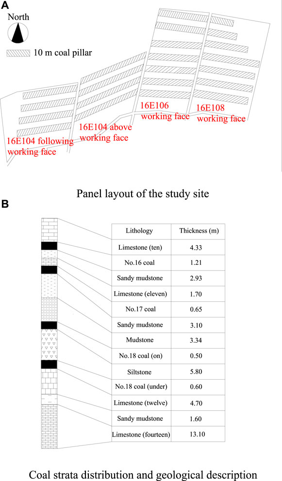
FIGURE 3. Panel layout of the study site and coal strata distribution and geological description, (A) Panel layout of the study site, (B) Coal strata distribution and geological description.
As strip mining (mining at a 10-m-wide interval) was applied before the 16E104, 16E106, and 16E108 working faces were filled, the direct roof above the working face showed a wavy flexual subsidence as a result of the load from the overlying strata while the overlying strata showed flexual subsidence as a result of its own weight (Deng et al., 2016; Zhou N. et al., 2019). As it was quite a long time since the working face was mined, after the first filling, the overlying roof remained the same state as before.
During the first filling, the last filling strip has to cure for 28 days. It takes 1–2 days to fill one single goaf. The working face cannot be remined until 38 days after the filling. Due to previous mining, the direct roof above the coal pillar in the first strip continued to sink flexually, with fine fractures being produced at the same time, but the direct roof in front of the working was not affected significantly, as shown in Figure 4.
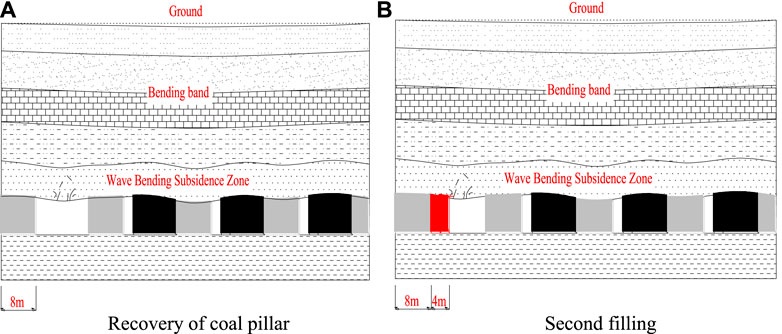
FIGURE 4. Change of direct roof, (A) Recovery of coal pillar, (B) Second filling.
After the last strip of coal pillar in the working face had been recovered, the working face has also been filled for the second time. Under the mine pressure, the direct roof above the original strip of coal pillar subsided flexually. The original goaf served as the “pier” due to the existence of the filling body. At the same time, more cracks began to appear inside the direct roof. At the end of the recovery of the working face, the subsidence of the wavy flexual subsidence zone above the working face gradually increased, as shown in Figure 5.
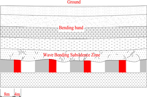
FIGURE 5. Replacement of all coal pillars.
The working faces of Jisuo Coal Mine include 16E104, 16E106 and 16E108, with an average depth of 120 m and an average length of 80 m. The width of the filling body is calculated according to the formula of total weight of overlying strata, as shown in (Eq. 1):
Where
In the filling scheme, the final setting strength of the filling body is calculated as 5 MPa, so the support strength per unit area is 5 MPa. The weight of overburden per unit area is 3 MPa, λ=1.6.
As shown in Table 1, increasing the filling width and strength can improve the stability of backfilling, but it also increases the filling cost. With the increase of mining depth, the stability of the strip filling body decreases, thus degrading the adaptability of the mining scheme. Considering the actual situation of the coal mine, the scheme with safety factor of 1.5 is selected for the scheme of “12 m filled 8 m left”.
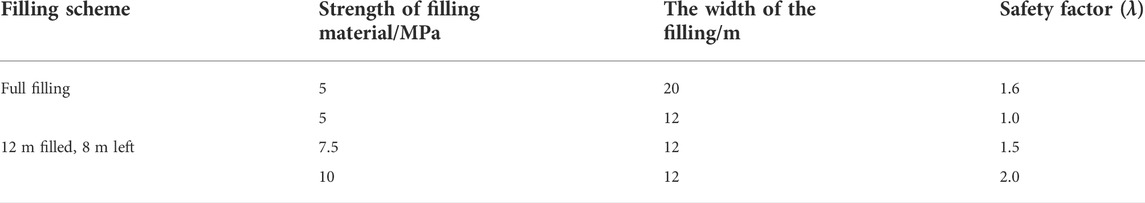
TABLE 1. Safety factors for different mining schemes.
1) Top-down filling system for Jisuo Coal Mine, first, the filling process system was installed in locations with suitable distance to the filling face to ensure short distance, low cost and convenient access. Second, filling aggregates, including coal gangue and construction waste, are crushed. Then, coal ash from power plants is utilized to mix well with the coal ganue, construction waste, cement and water with proper proportion in a mixer and stored in the material warehouse. The above processes form the aggregate processing system and paste material preparation system. The paste material conveying system uses a concrete pump to transport the filling material to the underground filling pump through the filling pipeline and to the goaf through the filling pipeline. Filling is operated in two stages: first filling and second filling after the residual coal pillar is recovered. The filling isolation system is composed of formwork and hydraulic pressure prop. The pathway for the filling material to enter into the well is independent from the pathway for coal recovery. The whole filling system can be divided into four parts: an aggregate processing system, a paste material preparation system, a paste material delivery system and a filling isolation system. The backfilling system and the process flow are shown in Figure 6.
2) Underground filling system to prevent the backfill concrete from flowing to other areas, a relatively closed room must be isolated so that the backfill concrete can well contact the roof. In this process, hydraulic pillars and building formwork are used as the frame. Braids are laid inside to form a temporary isolation wall, as shown in Figure 7. In this way, the backfill slurry can be pumped to the isolated backfill area through the pipe.
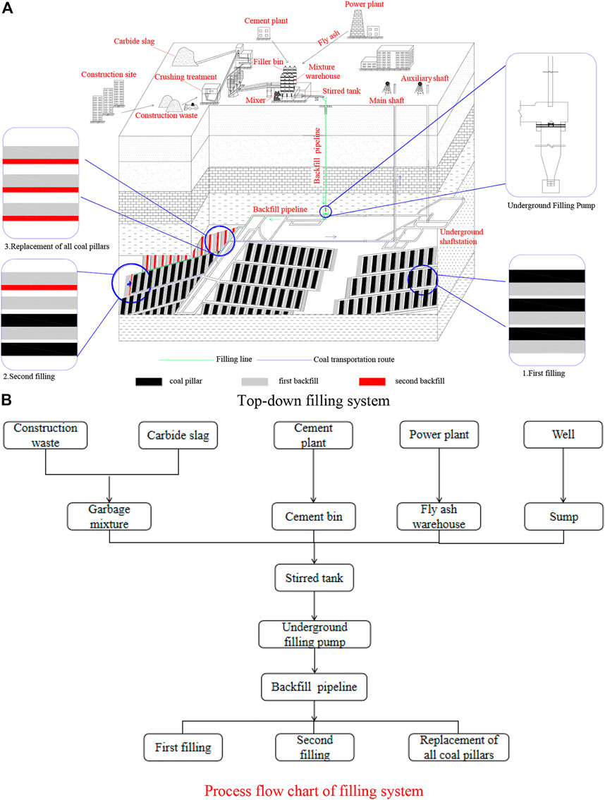
FIGURE 6. Filling system flow chart, (A) Top-down filling system, (B) Process flow chart of filling system.
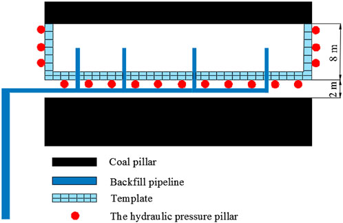
FIGURE 7. Transport diagram of filling paste.
To avoid serious pipeline blockage caused by filling pump faults and other reasons, a sedimentation tank was installed near the filling station in Jisuo Coal Mine. An emergency treatment ditch was excavated in the filling drilling chamber. Tees were mounted along the filling pipe at intervals to ensure that quick treatment was possible to avoid pipe blockage in case of any power interruption or machine shutdown.
According to the protection requirements of buildings and the actual mining situation of the mine, in order to ensure that the weight of overburden can be transferred to the “pier” successfully (Tan et al., 2017; Zhang et al., 2017), a filling and remining scheme of mined area (Coal 16) under village was adopted: first filling then mining, then strip remining and strip filling. In this scheme, the preparation for the first filling is to seal the area to be filled with building formwork and hydraulic pillars to prevent slurry leakage, and hang a layer of woven cloth on the inside to form a closed space. Because the coal seam inclination of Jisuo Coal Mine is small, four distribution pipes are evenly arranged in each filling strip to fill from the low end to the high end of the elevation. When the filling body reaches the expected strength, the middle pillar strip is mined, and the strip width is D1 = 8 m. After the coal pillar strip is completely recovered, the coal pillar is filled for the second time. The filling materials will connect with the initial filling body, serving as an integral filling pillar to support the roof. The backfilling width is D2 = 4 m.
1) According to the low-to-high direction of floor elevation, all mined-out strips in a working face are filled from north to south, with a filling width of 8 m. With concrete filling pouring in, stress meters are buried to monitor the stress change inside the filling body in real time.
2) There are generally 6–10 mined-out strips in a working face, and each will take 1–2 days to fill, thus in total it will take 15–25 days to fill all cavities in a working face.
3) When the last filling strip in the first working face meets the setting time of 28 days, the mining working face can be arranged according to the low-to-high direction of floor elevation, or from north to south in practice, and the original coal pillar strip can thus be mined. It takes 5–6 days for a coal pillar strip to complete mining. At this time, the second working face has been filled.
4) After the pillar strip mining is completed, the second backfilling shall be carried out in time with a backfilling width of 4 m, and corresponding dynamic monitors shall be arranged to monitor the corresponding variation characteristics of the surrounding rock in the goaf, including roof displacement, roof subsidence, bolt/anchor cable stress etc.
5) Generally, five to nine coal pillar strips need to be mined in a working face, thus it takes 25–45 days to complete all mining operations. Therefore, when the last pillar strip mining is completed, the first secondary filling body (4 m-wide filling body) in the first working face and the last primary filling body in the second working face have solidified for more than 28 days. At this time, the northernmost pillar strip of the adjacent second working face can be mined. The strip retreat mining method is adopted, with single hydraulic props and filling strips to support the roof, and full height mining is applied in operation. The filling sequence is shown in Figure 8.
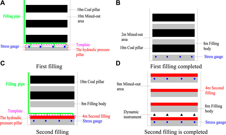
FIGURE 8. Filling sequence diagram, (A) First filling, (B) First filling completed, (C) Second filling, (D) Second filling is completed.
Aggregate processing mainly includes crushing, iron removal, impurity removal and screening. Construction waste is crushed in two stages by jaw crusher and impact crusher to ensure the particle size and the purity of filled aggregate can meet required standards. Jaw crusher is shown in Figure 9.
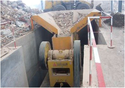
FIGURE 9. Jaw crusher.
In the process of backfill preparation, firstly, the processed aggregate is screened and subdivided according to the required ratio of backfilling materials. Secondly, it is mixed with fly ash, cementitious materials and water in a required proportion through the mixing system. Paste backfill concrete is thus formed, ready to be used for the next process. The filler bin and water sump are shown in Figure 10.
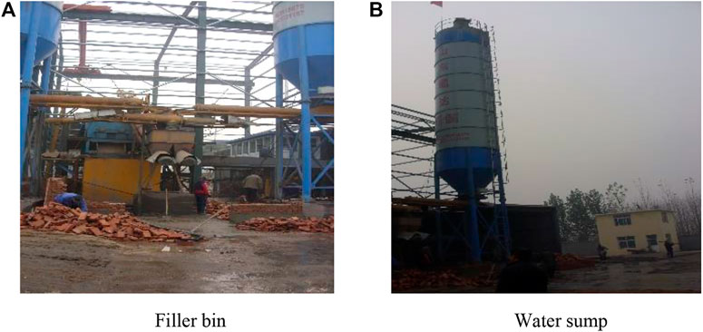
FIGURE 10. Backfill paste and concrete preparation system, (A) Filler bin, (B) Water sump.
As shown in Figure 11, fly ash and water are stored in one tank. The mixing plant is a three-stage continuous mixing plant, including three cylindrical devices with spiral stirring apparatus. The mixing plant has the following characteristics: 1) Three machines are installed on the same base to form a three-stage facility which can operate synchronously; 2) The upper machine entrance is square shaped and can be loaded automatically; 3) The intermediate machine is equipped with automatic water supply device; 4) The bottom machine is equipped with automatic raw material feeding and batching devices.
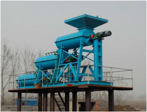
FIGURE 11. Concrete mixing device.
The system includes a concrete pump and a pipeline pumping system. The concrete pump is used to deliver the paste concrete to the filling working surface for filling. The mining concrete pump is one of the key equipment for goaf filling and mining, and its actual pumping capacity is not less than 120 m³/h. HGBS200/14-800 industrial filling pump, a large displacement concrete pump developed by China, is selected for the pumping purpose. The pipeline pumping system consists of filling standpipe, surface pipelines, underground trunk pipeline and underground branch pipeline. Pumping process: The concrete paste is delivered by two surface filling pumps to run through the ground pipes, drill pipes, tunnel pipes, working face pipes, three-way valves and then reach the slurry bin, from which it is pumped into the formwork to fill the goafs.
In order to master the control effect of strip filling and remining, strata movement monitoring was carried out on the underground filling mining face (Li and Aubertin, 2008; Widisinghe and Sivakugan, 2016; Liu et al., 2022). Monitoring indicators include roof displacement and vertical stress of filling body. Devices for filling body stress monitoring and roof dynamic monitoring are shown in Figure 12.
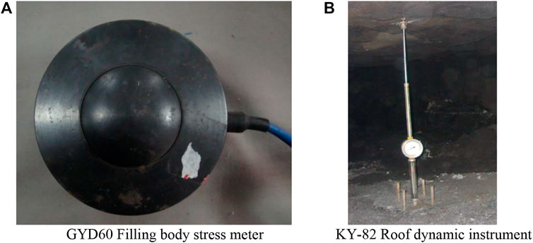
FIGURE 12. Monitoring equipment, (A) GYD60 Filling body stress meter, (B) KY-82 Roof dynamic instrument.
The function of the GYD60 filling body stress gauges are to measure the vertical stress in the backfilling area. Before the first strip filling, they were placed in the designated area, and the related monitoring equipment was also arranged, then filling commenced to cover the stress gauges and the stress data was collected and sent back to the collector through the communication line. The function of the KY-82 roof dynamic instruments is to measure the change of rock stratum displacement, monitor the cumulative subsidence of stope roof, and work with pressure measurement to reflect the characteristics of roof. The dynamic instrument was placed in the strip coal pillar, and space at regular intervals has been prepared to install the dynamic instruments. The observation data were collected on a regular basis.
Three groups of rock movement monitoring equipment were set for each 6 backfills, each containing four KY-82 roof dynamic meters and four GYD60 backfill stress meters. Four stress meters were placed in the filling body built in the first filling, with a length of 80 m and a width of 8 m. The spacing between two stress meters (used to monitor the vertical stress in the backfill body) was 20 m. After the second filling was completed, four roof dynamic instruments were placed in the 8-m-wide goaf to monitor the cumulative subsidence of stope roof, which worked simultaneously with the stress gauges to reflect the roof characteristics. The monitoring equipment layout is shown in Figure 13.
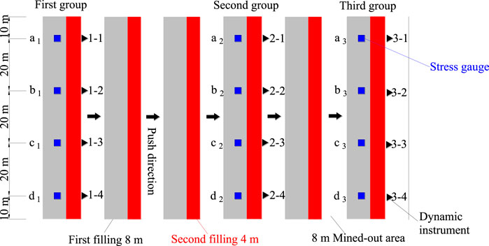
FIGURE 13. Top view of instrument layout.
In order to learn the surface subsidence and evaluate the effect of strip filling and re-mining, the surface subsidence observation stations were set up above the 16E104, 16E106, and 16E108 working faces of Jisuo Coal Mine. Monitoring indicators include vertical settlement, surface curvature and horizontal deformation. Observation lines were arranged along the 16E104, 16E106, and 16E108 working faces, and monitoring lines were arranged perpendicular to the 16E106 working face, as shown in Figure 14.
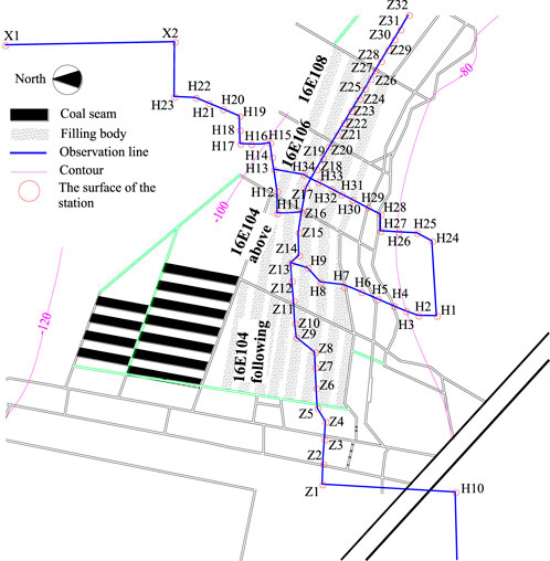
FIGURE 14. Location map of surface stations.
GYD60 stress meters were installed in the filling area in advance to monitor the vertical stress of the filling body (Helinski et al., 2010; Doherty et al., 2015). Three groups of strata movement monitoring equipment were set for every six filling bodies, and each group had four GYD60 stress meters. The monitoring results are shown in Figure 15.
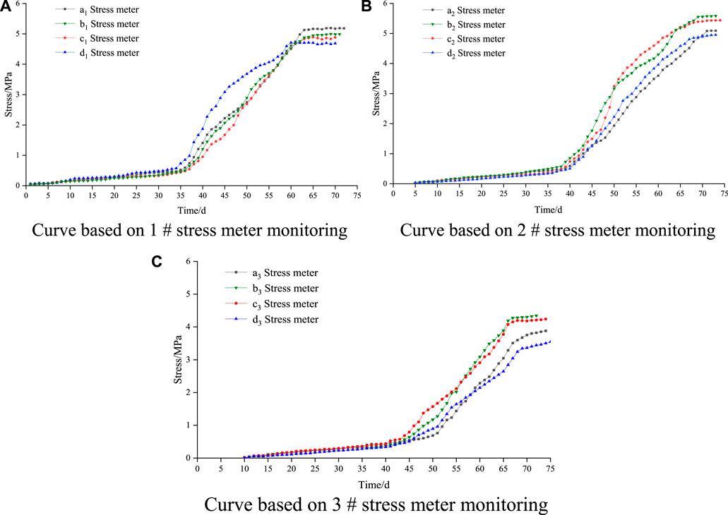
FIGURE 15. Stress evolution law, (A) Curve based on 1 # stress meter monitoring, (B) Curve based on 2 # stress meter monitoring, (C) Curve based on 3 # stress meter monitoring.
As can be seen from Figure 15A, the horizontal axis shows the number of days after the installation of the stress gauge, the longitudinal axis shows the stress value inside the filling body. The filling body of 1 # station became solidified within 35 days, and the stress change was relatively small. After 35 days, with the mining of coal pillar, the vertical stress in the filling area gradually increased. During the 50–60 days, the stress increased at the fastest speed. This phenomenon had an significant relationship with the distribution of bearing pressure in front of the working face until it reached the maximum value, and the internal stress of the filling body gradually levelled off during the 65–75 days. There were four groups of stress convergence values monitored by 1 # station, which were 4.74 MPa, 4.93 MPa, 5 MPa and 5.27 MPa respectively. As can be seen from Figure 15B, the change rate of the internal stress of the filling body at 2 # station was very small within the first 40 days, and the stress gradually increased during the 40–70 days. The rising rate was the fastest during the 55–65 days, and the stress reached the maximum value on about the 70th day and then gradually became stabilized. There were four groups of stress convergence values monitored by 2 # station, which were 5.04 MPa, 4.95 MPa, 5.54 MPa, and 5.66 MPa respectively. It can be seen from Figure 15C that the increase rate of internal stress in the filling body of 3 # measuring station began to accelerate on the 45th day. With the mining of the working face, the stress increased sharply during 50–70 days, and the stress reached the maximum on about the 70th day. There were four groups of stress convergence values monitored by 3 # station, which were 4.57 MPa, 4.62 MPa, 4.89 MPa and 4.92 MPa respectively.
The variation pattern of vertical stress in coal pillar recovery can thus be seen. With the replacement of coal pillar, the vertical stress increased in varying degrees. The stress change with stoping can be divided into three stages: It was relatively stable at the initial filling stage; stress increased gradually during the 35–45 days due to the occurrence of ground pressure; the stress gradually stabilized during the 65–75 days.
In the early days after the stress meters were installed in the filling body, the vertical stress barely increased, remaining at a stable state. It took about 65–75 days for the vertical stress to stabilize. The mine pressure distributed on the coal pillar can be transmitted smoothly to the filling body, and the filling belt was strong enough to bear the weight of the rock strata.
The displacement meter was used to monitor the roof displacement in the filling area, which could reflect the deformation law and the compression ratio of the filling body. Three groups of rock movement monitoring equipment were set for each 6 filling bodies, and each group was provided with four KY-82 roof dynamic instruments. Based on the monitoring results, the variation pattern of roof displacement was drawn. In these figures, the horizontal axis shows the time span for installing the displacement meters, and the vertical axis shows the underground roof displacement. The variation curve based on the monitoring results of the roof dynamic instrument is shown in Figure 16.
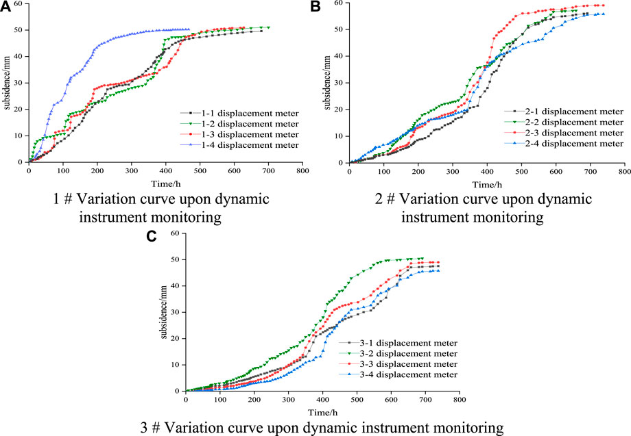
FIGURE 16. Variation curve upon dynamic instrument monitoring, (A) 1 # Variation curve upon dynamic instrument monitoring, (B) 2 # Variation curve upon dynamic instrument monitoring, (C) 3 # Variation curve upon dynamic instrument monitoring.
As shown in Figure 16A, by the monitoring results of 1 # station, the slope of curve is higher at first and the deformation rate of roof becomes increasingly faster, indicating that displacement took place between roof and floor; The deformation of roof was about 50 mm on about the 50th day, and then the slope decreased gradually. After about 70 days, the roof and floor reached a stable state, which was consistent with the vertical stress monitoring results. The abnormal curve of roof subsidence monitored by one to four instruments in 1 # station was due to the development of faults here, and thus the subsidence speed was fast; the changes of other subsidence curves were normal. The maximum roof displacement of the four groups monitored by 1 # station were 52 mm, 51 mm, 53 mm, and 52 mm respectively. The mining height was calculated as 1.21 m, and the average compression ratio of filling body was 4.3%. It can be seen from Figure 16B that the roof deformation monitored by 2 # station has increased significantly from the beginning, and the roof subsidence rate was the largest between the 45th day and 55th day. The roof subsidence levelled off around the 70th day, and the cumulative roof subsidence was 58 mm. The maximum moving amounts of the four groups monitored by 2 # station were 56 mm, 55 mm, 57 mm, and 58 mm respectively. The average compression ratio of the filling body was 47%. It can be seen from Figure 16C that the roof of 3 # station sank slowly from the beginning. With the mining of the working face, the roof subsidence increased gradually from Day 40, and the cumulative roof subsidence was 59 mm on about Day70. The maximum subsidence of the four groups monitored by the 3 # station were 57 mm, 56 mm, 59 mm, and 61 mm respectively. The average compression ratio of the filling body was 48%. After the mined-out area was filled, the roof rock beam became stable and the ground pressure became small, which means the requirement of replacing coal pillar has been met and the overlying strata was effectively controlled.
Surface deformation were surveyed to evaluate the effect of pillar extraction. The related indicators include the vertical settlement value, horizontal deformation value and surface curvature. All calculations were performed on the computer using specially designed programs.
The point with a subsidence of 10 mm was determined as the boundary point of surface subsidence basin according to the regulations (Chen et al., 2016; Janez et al., 2018). The angular parameters, including the strike boundary angle (59°), the inclined upward boundary angle (62°) and the inclined downward boundary angle (57°) were determined under this geological condition. The contour map of surface subsidence after mining of the test working face was drawn, as shown in Figure 17.
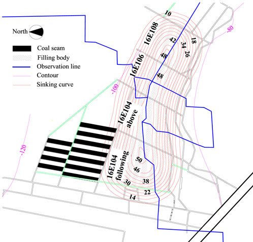
FIGURE 17. Surface subsidence contour map.
Surface subsidence is the vertical component of the surface movement vector of the main section (Qu et al., 2010). After the coal seam is mined, the stress state of the strata above the goaf is redistributed. With the increase of the goaf, different types of strata collapse and sink one after another until a stable condition is achieved (Guney and Gul, 2018; Zou et al., 2018a; Navid et al., 2019).
As shown in Figure 17, the three working faces of 16E104, 16E106, and 16E108 were adjacent to each other, and the overlying strata activities affected each other during the filling and mining of each working face. The subsidence values of the ground monitoring points at the same distance from the center line of the four working faces were of little difference and showed symmetry. From the initial movement to stability, the subsidence of the monitoring points in the middle of the working face was all greater than that at the boundary of the working face. Taking the monitoring points in the inclined direction of 16E104 working face as an example, after the surface was stable, the maximum subsidence was 50 mm, and the subsidence at the boundary was 14 mm. From the boundary of the working face to the center of the working face, the surface subsidence showed a steady increasing trend. The maximum subsidence in the inclined direction of 16E106 working face was 48 mm; The surface subsidence characteristics of 16E108 working face were similar to those of 16E104 working face. The subsidence increased steadily along the dip direction, and the maximum subsidence was 48 mm. The four working faces gave rise to a subsidence basin through surface subsidence, and the maximum subsidence value was in the center of the working face.
Detecting surface tilt is one of the main methods of fixed-point observation of surface deformation. Tilt refers to the change of subsidence per unit length of the surface. It mainly measures the relative movement in the vertical direction at a certain point on the surface. Inclination is the first derivative of surface subsidence. There are two groups of inclinations in different directions, the inclination between boundary point and maximum subsidence point has positive value and negative value.
As shown in Figure 18, the three working faces of 16E104,16E106, and 16E108 were adjacent to each other. The working face and its surrounding areas had tilted in different directions with varied degrees. The surface tilt value above the working face was larger than that at the boundary of the working face. The tilt contours in the middle of 16E104 working face and 16E108 working face were denser; On the whole, the surface tilt increased steadily from the boundary to the top of the working face, and the tilt degree increased gradually. The minimum surface tilt value around the three working faces was 0.05 mm/m, and the maximum surface tilt value above the working face was 0.65 mm/m. The surface tilt change was affected by the characteristics of surface subsidence. The surface tilt at the center of the four working faces was larger and the boundary tilt was smaller.

FIGURE 18. Surface tilt contour map.
Surface curvature represents the degree of surface subsidence and bending, Unit: mm/m2.
As shown in Figure 19, the three working faces of 16E104, 16E106, and 16E108 were adjacent to each other. The curvature contour at the boundary was denser than that above the working face, indicating that the surface curvature at the boundary was smaller than that above the working face; The greater the subsidence curvature of the curve, the more the subsidence bending will become. Due to the influence of mining, the subsidence curve at the roof of the working face had obvious depression and protrusion near the mining boundary, the subsidence curvature of the surrounding rock was less than that of the roof of the goaf, i.e., the roof protruded downward into the goaf, and a subsidence basin was formed on the surface above the goaf.
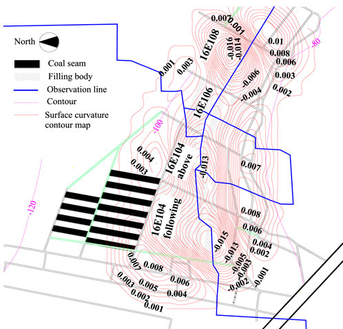
FIGURE 19. Surface curvature contour map.
The maximum curvature of 16E104 working face was 0.015 mm/m2; The minimum curvature was 0.001 mm/m2; The maximum curvature of 16E106 working face was 0.013 mm/m2, the minimum curvature was 0.002 mm/m2; The maximum curvature of 16E108 working face was 0.018 mm/m2; The minimum curvature was 0.001 mm/m2. Among the three working faces, the minimum curvature value was 0.001 mm/m2 and the maximum curvature value was 0.018 mm/m2, the variation characteristics of curvature was consistent with the surface subsidence and surface inclination. In conclusion, the filling effect was obvious and the surface subsidence was small.
Horizontal deformation represents the change in horizontal movement per unit length, Unit: mm/m. The physical meaning of positive horizontal deformation indicates that the surface is subject to tensile stress, while the physical meaning of negative value indicates the surface is subject to compressive stress.
As shown in Figure 20, the three working faces 16E104, 16E106, and 16E108 were adjacent to each other. Influenced by mining in the working face, the surface showed different degrees of horizontal deformation. Such deformation was relatively large in the south of 16E104 working face and the south of 16E108 working face, but the horizontal deformation of 16E106 working face was relatively small because it was in the middle of the three working faces. In addition, as it sank into a subsidence basin, the surface at the junction of the three working faces was subject to tensile stress, and the maximum horizontal deformation at the junction was 0.08 mm/m; the surface above the working face was subject to compressive stress and the maximum horizontal deformation was 0.16 mm/m.
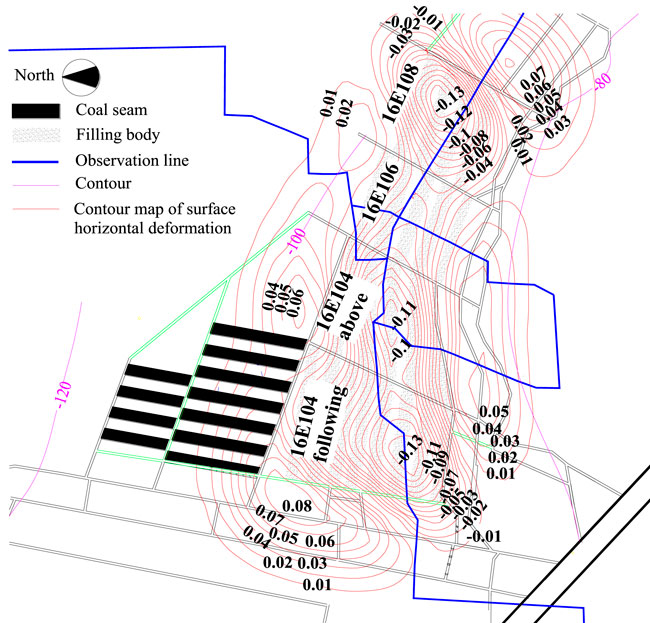
FIGURE 20. Surface horizontal deformation contour map.
Horizontal movement represents the horizontal component of the surface movement vector, and the variation of horizontal movement and tilt is similar.
As shown in Figure 21, horizontal movement from boundary point to working face increased gradually in three working faces of 16E104, 16E106, and 16E108. Due to the influence of mining, the contour lines of surface horizontal movement above the working face were dense. In the three working faces, the minimum horizontal movement was 0.5 mm and the maximum was 6 mm. As the terrain of the three working faces was relatively flat, from the curve distribution, the strike and inclination of surface movement generally conform to the general subsidence law. The horizontal movement deformation in the middle of 16E104 working face and 16E108 working face had an abrupt change, and the deformation value increased or decreased suddenly.
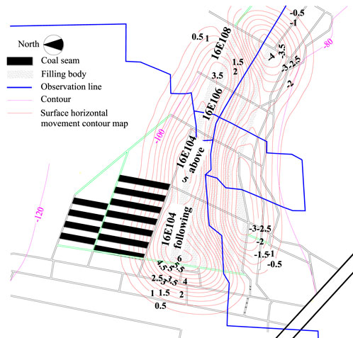
FIGURE 21. Surface horizontal movement contour map.
As mining of the working face proceeded, the surface subsidence gradually increased, and a subsidence basin was formed. According to the surface observation results, the maximum surface subsidence value was 44 mm (H13), and the subsidence at H32, H33, H34, H35, and H36 was 35 mm. By the follow-up observation results, the observation line of surface inclination and strike were gradually stabilized, and the 43 mm observed at point Z17 turned out to be the maximum change value of surface. Taking the subsidence process as a whole, there was no sudden change detected. The surface had continuous subsidence, and the whole subsidence basin fluctuated slightly with a fluctuation about 10 mm. In addition, it was concluded that the maximum surface subsidence after mining in 16E104, 16E106, and 16E108 working faces was 44 mm. The maximum inclination value was 0.65 mm/m; the maximum curvature value was 0.018 mm/m2; and the maximum horizontal deformation was 0.16 mm/m. All of them were less than the surface deformation value of buildings suffering from grade I damage.
Based on the comprehensive consideration of the deformation value of surface movement, the stability of composite support, social and economic benefits, the strip coal pillar under the village was re-mined, which improved the recovery rate of coal resources, prolonged the service life of the mine and maintained the sustainable development of the mine. Meanwhile, it fundamentally eliminated the hidden dangers of major disasters such as surface collapse and building damage caused by strip coal pillar instability, and ensured the happiness and stability of people’s life in the mining area, the harmonious development and long-term stability of society, which was of great practical and far-reaching significance.
In addition, Figure 22A showed the construction of filling formwork at the filling site, which was reinforced by hydraulic props to ensure that the concrete slurry would not leak. Figure 22B showed the effect of the filling body after removing the filling formwork. The filling body was well-structured and well-functioning, with no mechanical damage such as fracture.
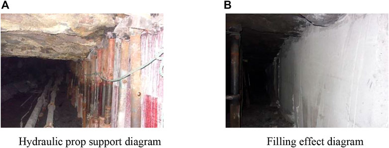
FIGURE 22. Filling support and effect diagram, (A) Hydraulic prop support diagram, (B) Filling effect diagram.
Taking the strip-filling and second-mining test in Jisuo Coal Mine as an example, this paper verified effectiveness of this technique by means of monitoring the underground mine pressure and observing the surface settlement. The results show that the strip re-mining technique after backfilling has an ideal effect in controlling surface settlement, effectively solving surface cracks and protecting ecology and surrounding environment.
1) In order to exploit the coal resources reserved under railways, rivers and buildings, a practical technique featuring strip re-mining after filling and disaster pre-control was proposed and implemented. With this technology, the construction waste is used as the aggregate to prepare the backfill material, and the self-developed three-stage continuous concrete mixing device and domestic large displacement concrete pump are used as the backfill power system. The workflow is determined as follows: aggregate processing, slurry preparation, slurry transportation and underground backfilling. The construction waste is used as the filling material to meet the needs of filling and mining. The whole schedule provides a new model for solid waste treatment of coal mine and green mining.
2) Taking Jisuo coal mine as the test object, this paper collected the data, through underground ground pressure monitoring and surface settlement observation, that the maximum stress is 5.27 MPa, the maximum roof subsidence is 59 mm, the maximum surface subsidence after mining is 44 mm, the maximum inclination is 0.65 mm/m, the maximum curvature value is 0.018 mm/m2 and the maximum horizontal deformation value is 0.16 mm/m. These deformation values did not reach the damage limit of surface buildings, which verified the success of the test scheme.
3) Practice has proved that the application of strip filling re-mining technique in coal mining, especially mines under railways, rivers and buildings, has improved the stress environment of the stope, played a positive role in controlling surface subsidence, and is of great significance to the sustainable development of the ecological environment around the mining area. Therefore, this technology can provide some useful clues for the remining research of foreign coal resources.
The original contributions presented in the study are included in the article/Supplementary Material, further inquiries can be directed to the corresponding authors.
Conceptualization, JH and AC; methodology, HB; software, XL; formal analysis, YS; resources, XW, JZ, and HL. All authors have read and agreed to the published version of the manuscript.
The study was financially supported by Taishan Scholars Project, the National Natural Science Foundation of China (Grant Number. 52174121 and 52104204), Natural Science Foundation of Shandong Province (ZR2021QE170).
We thank the reviewers for their constructive feedback.
The authors declare that the research was conducted in the absence of any commercial or financial relationships that could be construed as a potential conflict of interest.
All claims expressed in this article are solely those of the authors and do not necessarily represent those of their affiliated organizations, or those of the publisher, the editors and the reviewers. Any product that may be evaluated in this article, or claim that may be made by its manufacturer, is not guaranteed or endorsed by the publisher.
An, B. F., Miao, X. X., Zhang, J. X., Ju, F., and Zhou, N. (2016). Overlying strata movement of recovering standing pillars with solid backfilling by physical simulation. Int. J. Min. Sci. Technol. 26 (2), 301–307. doi:10.1016/j.ijmst.2015.12.017
Benzaazoua, M., Belem, T., and Bussie`re, B. (2002). Chemical factors that influence the performance of mine sulphidic paste backfill. Cem. Concr. Res. 32, 1133–1144. doi:10.1016/s0008-8846(02)00752-4
Cao, W. H., Wang, X. F., Li, P., Zhang, D. S., Sun, C. D., and Qin, D. (2018). Wide strip backfill mining for surface subsidence control and its application in critical mining conditions of a coal mine. Sustainability 10 (3), 700. doi:10.3390/su10030700
Cao, Z. Z. (2017). Study on instability mechanism and rock burst mechanism of coal pillar in roadway filling mining. China University of Mining and Technology.Beijing, China.
Chang, Q. L., Chen, J. H., Zhou, H. Q., and Bai, J. B. (2014). Implementation of paste backfill mining technology in Chinese coal mines. Sci. World Journa. doi:10.1155/2014/821025
Chen, Q. F., Zhou, K. P., and Wang, L. L. (2010). Stress field evolution law of mining environment reconstructing structure with change of filling height. J. Cent. South Univ. Technol. 17 (4), 738–743. doi:10.1007/s11771-010-0549-6
Chen, S. J., Wang, H. L., and Wang, H. Y. (2016). Strip coal pillar design based on estimated surface subsidence in eastern China. Rock Mech. Rock Eng. 49 (9), 1–10. doi:10.1007/s00603-016-0988-y
Cihangir, F., Ercikdi, B., Kesimal, A., Deveci, H., and Erdemir, F. (2015). Paste backfill of high-sulphide mill tailings using alkali-activated blast furnace slag: Effect of activator nature, concentration and slag properties. Miner. Eng. 83, 117–127. doi:10.1016/j.mineng.2015.08.022
Deng, X. J., Zhang, J. X., Kang, T., and Han, X. L. (2016). Strata behavior in extra-thick coal seam mining with upward slicing backfilling technology. Int. J. Min. Sci. Technol. 26 (4), 587–592. doi:10.1016/j.ijmst.2016.05.009
Doherty, J. P., Hasan, A., Suazo, G. H., and Fourie, A. (2015). Investigation of some controllable factors that impact the stress state in cemented paste backfill. Can. Geotech. J. 52 (12), 1901–1912. doi:10.1139/cgj-2014-0321
Du, X. J., Feng, G. R., Qi, T. Y., Guo, Y., Zhang, Y. J., and Wang, Z. H. (2019a). Failure characteristics of large unconfined cemented gangue backfill structure in partial backfill mining. Constr. Build. Mater. 194, 257–265. doi:10.1016/j.conbuildmat.2018.11.038
Du, X. J., Feng, G. R., Zhang, Y. J., Wang, Z., Guo, Y., and Qi, T. (2019b). Bearing mechanism and stability monitoring of cemented gangue fly ash backfill column with stirrups in partial backfill engineering. Eng. Struct. 188, 603–612. doi:10.1016/j.engstruct.2019.03.061
Ercikdi, B., and Yilmaz, T. (2019). Strength and microstructure properties of cemented paste backfill; Effect of class-c fly ash . Dokuz Eylul Univ. Fac. Eng. J. Sci. Eng. 21 (61), 15–23. doi:10.21205/deufmd.2019216102
Fall, M., Belem, T., Samb, S., and Benzaazoua, M. (2007). Experimental characterization of the stress–strain behaviour of cemented paste backfill in compression. J. Mat. Sci. 42 (11), 3914–3922. doi:10.1007/s10853-006-0403-2
Ghasemi, E., Ataei, M., and Shahriar, K. (2014). An intelligent approach to predict pillar sizing in designing room and pillar coal mines. Int. J. Rock Mech. Min. Sci. (1997). 65 (75), 86–95. doi:10.1016/j.ijrmms.2013.11.009
Guney, A., and Gul, M. (2018). Analysis of surface subsidence due to longwall mining under weak geological conditions: Turgut basin of Yataan-Mula (Turkey) case study, Int. J. Min., 33. 1–17. doi:10.1080/17480930.2018.1443691
Guo, G. L., Zha, J. F., Wu, B., and Jia, X. G. (2007). Study of “3-step mining”subsidence control in coal mining under buildings. J. China Univ. Min. Technol. 17 (3), 316–320. doi:10.1016/s1006-1266(07)60096-0
Hao, J., Shi, Y. K., Lin, J. H., Wang, X., and Xia, H. C. (2019). The effects of backfill mining on strata movement rule and water inrush: A case study. Processes 7 (2), 66. doi:10.3390/pr7020066
Helinski, M., Fahey, M., and Fourie, A. (2010). Coupled two-dimensional finite element modelling of mine backfilling with cemented tailings. Can. Geotech. J. 47 (11), 1187–1200. doi:10.1139/t10-020
Huang, Y., Tian, F., Wang, Y. J., Wang, M., and Hu, Z. L. (2014). Effect of coal mining onvegetation disturbance and associated carbon loss. Environ. Earth Sci. 73 (5), 2329–2342. doi:10.1007/s12665-014-3584-z
Janez, R., Drago, P., and Milivoj, V. (2018). Analysis of dynamic surface subsidence at the underground coal mining site in velenje. Slovenia through Modified Sigmoidal Function. Minerals 8 (2), 74. doi:10.3390/min8020074
Jiang, N., Wang, C. X., Pan, H. Y., Yin, D. W., and Ma, J. B. (2020). Modeling study on the influence of the strip filling mining sequence on mining-induced failure. Energy Sci. Eng. 8 (6), 2239–2255. doi:10.1002/ese3.660
Li, L., and Aubertin, M. (2008). An improved analytical solution to estimate the stress state in subvertical backfilled stopes. Can. Geotech. J. 45 (10), 1487–1496. doi:10.1139/t08-060
Li, X. L., Chen, S. J., and Wang, S. (2021). Study on in situ stress distribution law of the deep mine taking Linyi Mining area as an example. Adv. Mater. Sci. Eng. 9 (4), 5594181. doi:10.1155/2021/5594181
Liu, H. Y., Zhang, B. Y., and Li, X. L. (2022). Research on roof damage mechanism and control technology of gob-side entry retaining under close distance gob. Eng. Fail. Anal. 138 (5), 106331. doi:10.1016/j.engfailanal.2022.106331
Liu, J. W., Sui, W. H., and Zhao, Q. J. (2017). Environmentally sustainable mining: A case study of intermittent cut-and-fill mining under sand aquifers. Environ. Earth Sci. 76 (16). doi:10.1007/s12665-017-6892-2
Liu, S. M., Li, X. L., Wang, D. K., and Zhang, D. (2020). Investigations on the mechanism of the microstructural evolution of different coal ranks under liquid nitrogen cold soaking. Energy Sources A: Recovery Util. Environ. Eff., 1–17. doi:10.1080/15567036.2020.1841856
Luan, H. J., Jiang, Y. J., Lin, H. L., and Wang, Y. H. (2017). A new thin seam backfill mining technology and its application. Energies 10 (12), 2023. doi:10.3390/en10122023
Mkadmi, N. E., Aubertin, M., and Li, L. (2014). Effect of drainage and sequential filling on the behavior of backfill in mine stopes. Can. Geotech. J. 51 (51), 1–15. doi:10.1139/cgj-2012-0462
Mohamed, A. S, and Li, L (2017). Numerical investigation of the stresses in backfilled stopes overlying a sill mat. J. Rock Mech. Geotechnical Eng. 9 (3), 490–501. doi:10.1016/j.jrmge.2017.01.001
Mu, W. Q., Li, L. C., Guo, Z. P., Du, Z. W., and Wang, S. X. (2019). Novel segmented roadside plugging-filling mining method and overlying rock mechanical mechanism analyses. Energies 12 (11), 2073. doi:10.3390/en12112073
Navid, H., Ali, M., Misagh, M., Aref, F., and Kamyar, T. (2019). Fuzzy evaluation method for the identification of subsidence susceptibility in an underground mine (case study in Tabas coal mine of Iran). Nat. Hazards 99 (2), 797–806. doi:10.1007/s11069-019-03774-2
Ning, S., Zhu, W. B., Yi, X. Y., and Wang, L. L., (2021). Evolution law of floor fracture zone above a confined aquifer using backfill replacement mining technology. Geofluids, doi:10.1155/2021/8842021
Qian, M. G., Miao, X. X., and Xu, J. L. (2007). Green mining of coal resources harmonizing with environment. J. China Coal Soc. 32 (1), 1–7. doi:10.13225/j.cnki.jccs.2007.01.001
Qu, Q. D., Yao, Q. L., Li, X. H., and Rong, T. Y (2010). Key factors affecting control surface subsidence in backfilling mining. J. Min. Saf. Eng. 27 (4), 458–462.
Qu, X. K., Jiang, F. X., Wang, H. T., Zhu, S. T., Zhang, M., Xu, K., et al. (2017). Study on the mechanism of coal seam impact induced by pillar instability in goaf. J. Min. Saf. Eng. 34 (6), 1134–1140. doi:10.13545/j.cnki.jmse.2017.06.015
Raffaldi, M. J., Seymour, J. B., Richardson, J., Zahl, E., and Board, M. (2019). Cemented paste backfill geomechanics at a narrow-vein underhand cut-and-fill mine. Rock Mech. Rock Eng. 52 (12), 4925–4940. doi:10.1007/s00603-019-01850-4
Shao, X. P., Wang, L., Li, X., Fang, Z. Y., Zhao, B. C., Liu, E. S., et al. (2021). Conversion mechanism of a continuous pressure arch structure in strip filling mining. Arab. J. Geosci. 14, 1825. doi:10.1007/s12517-021-07918-2
Sun, D. Q., Wu, Q. L., Li, X. Y., Zhang, Z. M., Xu, X. T., Li, Y., et al. (2021). Sensitivity analysis and numerical simulation study on main controlling factors of surface movement and deformation in strip filling mining under thick unconsolidated layers. Geofluids 2021. doi:10.1155/2021/6615937
Sun, Q., Zhou, N., Song, W. J., and Zhao, X. (2021). Risk assessment and prevention of surface subsidence under buildings by cemented paste filling and strip mining methods: a case study. Adv. Civ. Eng.. doi:10.1155/2021/9965279
Sun, Q., Zhang, J. X., and Zhou, N. (2018). Study and discussion of short-strip coal pillar recovery with cemented paste backfill. Int. J. Rock Mech. Min. Sci. 104, 147–155. doi:10.1016/j.ijrmms.2018.01.031
Sun, X. K., and Wang, W. (2011). Theoretical research on high water material replacement mining the strip coal pillar above confined aquifer. J. China Coal Soc. 36 (6), 909–913. doi:10.13225/j.cnki.jccs.2011.06.018
Tan, Y., Guo, W. B., Bai, E. H., Yang, D. M., Xu, G. S., and Yan, H. (2017). Overburden failure induced by instability of coal pillar in strip wongawilli mining. J. Coal Sci. 42 (7), 1656–1662. doi:10.13225/j.cnki.jccs.2016.1163
Tuylu, S. (2022). Investigation of the effect of using different fly ash on the mechanical properties in cemented paste backfill. J. Wuhan. Univ. Technol. -Mat. Sci. Ed. 37 (4), 620–627. doi:10.1007/s11595-022-2576-1
Wang, S., Li, X. L., and Qin, Q. Z. (2022). Study on surrounding rock control and support stability of Ultra-large height mining face. Energies 15 (8), 6811. doi:10.3390/en15186811
Widisinghe, S, and Sivakugan, N, (2016). Vertical stress isobars for silos and square backfilled mine stopes. Int. J. Geomech. 16 (2). doi:10.1061/(asce)gm.1943-5622.0000499
Xuan, D. Y., and Xu, J. L. (2017). Longwall surface subsidence control by technology of isolated overburden grout injection. Int. J. Min. Sci. Technol. 27, 813–818. doi:10.1016/j.ijmst.2017.07.014
Yan, H., Zhang, J. X., Zhang, S., and Zhou, N. (2018). Physical modeling of the controlled shaft deformation law during the solid backfill mining of ultra-close coal seams. Bull. Eng. Geol. Environ. 78, 3741–3754. doi:10.1007/s10064-018-1335-1
Zhang, J. X., Sun, Q., Zhou, N., Jiang, J. Q., Germain, D., and Abro, S. (2016). Research and application of roadway backfill coal mining technology in Western coal mining area. Arab. J. Geosci. 9 (10). doi:10.1007/s12517-016-2585-5
Zhang, X. G., Lin, J., Liu, J. X., Li, F., and Pang, Z. Z. (2017). Investigation of hydraulic-mechanical properties of paste backfill containing coal gangue-fly ash and its application in an underground coal mine. Energies 10 (9), 1309. doi:10.3390/en10091309
Zhou, D. W., Wu, K., Bai, Z. H., Zhenqi, H., Liang, L., Yuankun, X., et al. (2019). formation and development mechanism of ground crack caused by coal mining: Effects of overlying key strata. Bull. Eng. Geol. Environ. 78 (2), 1025–1044. doi:10.1007/s10064-017-1108-2
Zhou, N., Yan, H., Jiang, S. Y., and Sun, Q. (2019). Stability analysis of surrounding rock in paste backfill recovery of residual room pillars. Sustainability 11 (2), 478. doi:10.3390/su11020478
Zhou, X. M., Wang, S., and Li, X. L. (2022). Research on theory and technology of floor heave control in semicoal rock roadway: Taking longhu coal mine in Qitaihe mining area as an Example. Lithosphere 2022 (11), 3810988. doi:10.2113/2022/3810988
Zhu, Li, Guo, R. F., and Jia, Q. C. (2020). Research on the influence of slurry filling on the stability of floor coal pillars during mining above the room-and-pillar goaf: A case study. Geofluids 2020 (1), 1–21. doi:10.1155/2020/8861348
Zhu, W. B., Yu, S. C., Xuan, D. Y., and Shan, Z. J (2018). Experimental study on excavating strip coal pillars using caving zone backfill technology. Arab. J. Geosci. 11 (18). doi:10.1007/s12517-018-3914-7
Zhu, X. J., Guo, G. L., Liu, H., Peng, X. N., Yang, X. Y., and Peng, Z. B. (2020). Research on the stability evaluation model of composite support pillar in backfill-strip mining. Math. Problems Eng. 2020, 11. doi:10.1155/2020/3138258
Zou, M. J., Liu, Y. Z., and Huang, Z. Q. (2020). Geological control of irreducible water within the coal matrix and its quantified evaluation model. ACS Omega 5 (16), 9540–9549
Zou, M. J., Wei, C. T., Zhang, M., and Lv, X. C. (2018a). Quantification of gas and water transfer between coal matrix and cleat network during drainage process. J. Energy Res. Techn. 140 (3), 032905-1–9
Keywords: second-mining of strip coal pillar, construction waste, backfill material, partial backfilling, subsidence control, field monitoring
Citation: Hao J, Chen A, Li X, Bian H, Shi Y, Wang X, Zhao J and Liu H (2022) A case study of pillar extraction techniques based on strip-filling and second-mining method. Front. Earth Sci. 10:1051245. doi: 10.3389/feart.2022.1051245
Received: 22 September 2022; Accepted: 24 October 2022;
Published: 11 November 2022.
Edited by:
Mingjun Zou, North China University of Water Resources and Electric Power, ChinaReviewed by:
Yongqiang Cui, China University of Petroleum, ChinaCopyright © 2022 Hao, Chen, Li, Bian, Shi, Wang, Zhao and Liu. This is an open-access article distributed under the terms of the Creative Commons Attribution License (CC BY). The use, distribution or reproduction in other forums is permitted, provided the original author(s) and the copyright owner(s) are credited and that the original publication in this journal is cited, in accordance with accepted academic practice. No use, distribution or reproduction is permitted which does not comply with these terms.
*Correspondence: Anfa Chen, YW5mYTEwODMwOEAxNjMuY29t; Xuelong Li, bGl4bGN1bXRAMTI2LmNvbQ==
Disclaimer: All claims expressed in this article are solely those of the authors and do not necessarily represent those of their affiliated organizations, or those of the publisher, the editors and the reviewers. Any product that may be evaluated in this article or claim that may be made by its manufacturer is not guaranteed or endorsed by the publisher.
Research integrity at Frontiers
Learn more about the work of our research integrity team to safeguard the quality of each article we publish.