 Zhenfeng Wang1,2
 Yu Wang
- 1School of Energy Science and Engineering, Henan Polytechnic University, Jiaozuo, China
- 2Yimei Group Postdoctoral Workstation, Yima, China
- 3Henan Xuchang Xinlong Mining Coal, Xuchang, China
This study aims to reasonably determine the influence radius of pressure relief of energy-accumulating blasting and water injection in the Liangbei Coal Mine and effectively eliminate local stress concentration and coal seam outburst risk. The change in gas parameters in each test hole before and after energy-accumulating blasting and water injection is determined through ANSYS/LSDYNA numerical simulation, theoretical analysis and calculation, and the application of the gas parameter method in the 32051 heading face of the Liangbei Coal Mine. The influence radius of pressure relief technology of energy-accumulating blasting and water injection in the Liangbei Coal Mine in the direction of energy-accumulating trough is studied, which provides reliable data for the layout parameters of energy-accumulating blasting and water injection hole in the working face of the Liangbei Coal Mine. The experimental results are as follows: 1) The simulation via ANSYS/LSDYNA shows that a blasting cavity is formed by an explosive shock wave in the borehole. The diameter of the blasting cavity in the energy-accumulating direction is 42 cm, which is 10 times the diameter of the energy-accumulating blasting and water injection hole. The diameter of the blasting cavity in the non-energy-accumulating direction is 14 cm, which is 3.3 times the diameter of the energy-accumulating blasting and water injection hole. The stress in the energy-accumulating direction is 2.9 times larger than that in the non-energy-accumulating direction. The crack length in the energy-accumulating direction is 294 cm, and the crack length in the non-energy-accumulating direction is 80 cm. 2) Theoretical analysis and calculation present that the crushing area of shaped charge blasting is 39 cm, the fracture area is 267 cm, and the vibration area is 159 cm. 3) Comparison of the change in gas parameters of each test hole in the field experiment before and after energy-accumulating blasting and water injection indicates that the influence radius of pressure relief in the direction of energy-accumulating trough is 300 cm. 4) The layout of energy-accumulating blasting and water injection in the working face of the Liangbei Coal Mine with 550 cm borehole spacing demonstrates that the verification index of gas drilling decreases, the analytical values (Δh2) decrease from 120–140 Pa to 100–120 Pa, the drilling cutting weight (S) decreases from 3.2 to 4.6 kg/m to 3.0–3.8 kg/m, and stress is released and transferred to deep coal. This study has guiding significance for outburst elimination by local arrangement of energy-gathering blasting and water injection borehole in the working face of the Liangbei Coal Mine.
Introduction
Energy-accumulating blasting is one kind of directional blasting, forming energy-accumulating flow in specific direction to cut coal body, creating large cracks, increasing the permeability of coal body, and eliminating local stress concentration of coal body (Zhai, 2010). Wei found that pressure relief blasting technology can reduce the degree of stress concentration in coal and rock mass and effectively avoid the occurrence of rock burst disasters (Wei et al., 2011). Cao determined that loose blasting can increase the length of pressure relief zone in front of stope (Cao et al., 2013). Dou found that the use of loose blasting in strong impact danger zone can make the peak stress transfer to the deep coal body (Dou et al., 2018). Guo discovered that the superposition effect of stress wave resulted in the formation of uniform pressure zone in the middle section of two blasting holes and its neighborhood (Guo et al., 2020; Guo et al., 2021). Yang used ANSYS/LSDYNA numerical simulation to study the cohesive blasting parameters of the surrounding hole and found that cohesive blasting can enhance the stress superposition on the connecting line of the surrounding hole, and the blasting stress is 1.4 times of that without cohesive tube blasting (Yang et al., 2019). Song used the ANSYS/LSDYNA software to study the concentrated blasting of the same segment with porous structure and found that the cracks mainly expanded along the connection line of blast holes, and the coal between adjacent blast holes was subjected to two blasting actions (Song et al., 2018). The effective influence range of cohesive blasting can be determined by comparing the change in parameters in the test hole (Gao et al., 2019; Guo et al., 2019). Blasting hole spacing has an important influence on the presplitting effect; too small will increase engineering quantity, whereas too large will alter the effect (Zhang et al., 2019). Hua found that when the charge length is fixed, the tangential maximum tensile stress decreases with the increase in hole spacing (Hua et al., 2020). Kim found that the energy transfer efficiency of hydraulic presplitting blasting was higher than that of ordinary presplitting blasting in tunnel excavation and surrounding rock vibration detection (Kim, 2007). Using a superdynamic strain test system, Zong found the advantage of hydraulic blasting by analyzing the stress and strain distribution characteristics of water and air blasting under different uncoupling coefficients (Zong and Luo, 2006). Bingxiang studied the control of water pressure to increase the amount of fracturing and found that with the increase in pressure, detonation cracks continued to expand. Under the action of detonation pressure, the propagation of coal joint cracks extended (Huang et al., 2011; Huang and Li, 2015; Li et al., 2022a; Li et al., 2022b). Wei studied the influence of hydrolyzing coupling charge structure on explosion stress fading and found that the hydrolyzing coupling coefficient of 2.57 is the best coefficient to induce cracking of gun hole (Yuan et al., 2018; Yuan et al., 2019). Low permeability of coal seam and difficult gas drainage, found that dynamic multifield coupling model of gas drainage (Zhang et al., 2021; Zhang et al., 2022). The action mechanism, influence parameters, and blasting results of concentrated energy blasting and hydraulic blasting were studied deeply by the above scholars, but most of them were about deep hole concentrated blasting. Local coal affected by mining and coal pillar will produce local stress concentration area. Few scholars have studied the energy-accumulating blasting and water injection technology, ignoring the effect of the wave energy of adjacent holes in the process of condensed energy detonation of local shallow holes.
Gas parameter meters are used to detect borehole flow, gas concentration, and borehole negative pressure. The pressure relief ring formed by explosive injection of coal, crack propagation in coal, flow rate, and gas concentration in borehole will change. Using a gas parameter meter to compare the numerical changes of borehole flow and gas purity before and after borehole cohesive energy explosion can determine whether the cracks around the borehole expand.
This study aims to reasonably determine the influence radius of energy-accumulating blasting and water injection in the direction of energy-accumulating trough in the Liangbei Coal Mine. Numerical simulation, theoretical analysis, and gas parameter method are used to carry out a field experimental study on the influence radius of energy-accumulating blasting and water injection in the direction of energy-accumulating trough. Reasonable radius parameters of energy-accumulating blasting and water injection in the direction of energy-accumulating trough provide reliable and reasonable data for the layout parameters of local energy-accumulating blasting and water injection holes in the Liangbei Coal Mine.
Engineering background
The elevation height of the 32051 intermediate base entry is -484.61–456.7 m, the buried depth is 568.3–595.5 m, the design length is 715.5 m, the average coal seam thickness is 4.5 m, the gas content is 2.41–7.57 m3/t, the gas pressure is 0–0.8 Mpa, the damage type of coal in mining section 32 is type V, and the gas permeability coefficient of coal seam is between 0.02011 and 0.0472 m2/Mpa2·d−1, which is difficult to extract. The consistent coefficient of coal is 0.151–0.33, and the coal quality is soft. The initial velocity of gas release is 16.81–36.8 mmHg. The 32,051 working face in the Liangbei Coal Mine has outburst hazard.
To solve the safety hazard of stress concentration in front of excavation work caused by a small coal pillar during water conservancy measures of the bottom roadway in the Liangbei Coal Mine, a large number of large-diameter outburst elimination boreholes should be constructed in accordance with the coal seam thickness in the excavation face. Lan found that a large number of boreholes can transfer the stress concentration area to the end of pressure relief hole and deep surrounding rock (Liu et al., 2007; Tan, 2011; Liu et al., 2012; Lan et al., 2013). Nevertheless, the amount of drilling is enormous, excessive drilling construction seriously affects the tunneling speed of the excavation face, and the effect of eliminating stress concentration is limited. Serious shortage of drill footage per month occurs, and mining and excavation replacement is seriously affected from both production and safety perspectives (Figure 1).
FIGURE 1. Schematic of the hydraulic flushing model.
In consideration of the above factors, directional pressure relief technology of energy-accumulating blasting and water injection in the Liangbei Coal Mine is researched. The influence radius of energy-accumulating blasting and water injection is studied to arrange blasting holes in the working face of the Liangbei Coal Mine reasonably.
Theoretical analysis
In accordance with the failure characteristics of coal, the area affected by energy-accumulating blasting and water injection can be divided into three zones: crushing zone, fracture zone, and blasting vibration zone. Owing to the energy-accumulating effect of the energy-accumulating pipe in the direction of the energy-accumulating trough in energy-accumulating blasting and water injection, the influence range of the energy-accumulating pipe is larger than that of deep hole blasting. In the calculation, a high detonation velocity is used to replace the energy-accumulating effect of the energy-accumulating pipe. The values of each parameter in the formula are shown in the following parameter data table.
Calculation of the scope of crushing zone
During energy-accumulating blasting and water injection, the blasting shock wave formed by the explosive is much larger than the compressive strength of the coal body, and the coal body is broken. Given that the crushing zone is under the constraint condition of the coal body, most of the energy consumption of the shock wave is consumed in the plastic deformation, crushing, and heating of the coal body, resulting in a rapid decline in the energy of the shock wave. The shock wave energy is insufficient to crush the coal body, so the radius of the crushing zone is small. The estimation formula is
In Eq. 1: Rc-radius of the crushing zone, m; Rb-cavity radius after blasting, m; σc-uniaxial compressive strength of coal, Pa; ρs-coal density, kg/m³; c-P-wave velocity of coal, 1,200–1,500 m/s.
The cavity radius formed after energy-accumulating blasting and water injection is
In Eq. 2: rb-blasting hole radius, cm; pm-average detonation pressure of explosives, Pa.
In Eq. 3: D-explosive detonation velocity, m/s; σ0-coal strength under multidirectional stress, Pa.
Substituting the parameters into Eqs 1–4 leads to Rc=39 cm.
Calculation of the scope of fracture zone
When the shock wave passes through the crushing zone, it continues to propagate to the coal body, but its energy attenuation is insufficient to cause deformation and fracture of the coal body. At this time, the high-temperature and high-pressure gas enters the coal fracture through the crushing zone and forms tensile stress in the fracture. Given that the tensile strength of coal is considerably less than its compressive strength, the coal is easy to form tensile failure. When the tensile stress formed by gas is greater than the tensile strength of coal, coal tensile failure and crack propagation occur. According to the quasi-static pressure of detonation gas, the calculation formula for fracture zone is
In Eq. 5: pj-quasi-static pressure acting on borehole wall, Pa. When the hole is not coupled, there is
In Eq. 6: rc-charge radius, cm.
Substituting the parameters into Eqs 5, 6 yields Ra=267 cm.
Calculation of the scope of blasting vibration zone
Outside the fracture zone, the stress generated by blasting shock wave and high-temperature and high-pressure gas is not enough to cause tensile and compressive failure of the coal body. It can only cause vibration of coal unit particle and local vibration of the coal body. The calculation formula for vibration zone is
In Eq. 7: Rs-radius of blasting vibration zone, cm; q-loading of coal per unit volume, 1.2 kg/m³.
Substituting the parameters into Eq. 7 results in Rs=159 cm.
In summary, the influence range of explosion fissure in the direction of energy-accumulating blasting and water injection includes the crushing and fracture zones. The scope of influence is
In Eq. 8: R-radius of energy-accumulating blasting and water injection, cm.
Substituting the parameters into Eq. 8 gives R=306 cm.
Numerical simulation
Numerical model
The influence range of directional pressure relief and increased permeability of energy-accumulating blasting and water injection in the Liangbei Coal Mine is studied. The ANSYS/LSDYNA numerical simulation software is used to establish a one-half three-dimensional calculation model. The model size is 600 cm×300 cm×1 cm. The borehole diameter is 4.2 cm, the explosive diameter is 2.4 cm, and the energy-accumulating pipe thickness is 0.2 cm (Figure 2). The model consists of coal, water, energy-accumulating pipe, and explosives. In the common joint of water, energy-accumulating pipe, and explosive, there is a gap between the explosive and borehole, which belongs to water-uncoupled charge. The calculation step is 0.9 μs. A coal failure criterion is added. Constraints are applied in z direction to the front and rear planes of the model, unreflected boundary condition constraints on the up, right, and left boundary of the model, and in y direction to the bottom planes of the model.
FIGURE 2. Schematic of the energy-accumulating blasting and water injection model.
Material parameters and state equations
The coal material parameters in the simulation are shown in Table 1.
TABLE 1. Coal parameters.
For the elastic–plastic material constitutive model of coal body, the keyword MAT_PLASTIC_ KINEMATIC in LSDYNA is defined.
For the three-stage emulsified explosive, the keyword MAT_HIGH_EXPLOSIVE_BURN in LSDYNA is defined. Table 2 indicated the parameters. The explosive change is described by the JWL equation of state:
TABLE 2. Explosive parameters.
The MAT_NULL material model in LSDYNA is defined for air, and the equation of state is defined by LINEAR_POLYNOMIAL. Table 3 presents the parameters.
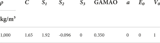
TABLE 3. Water parameters.
The MAT_PLASTIC_KINEMATIC material model in LSDYNA is defined for the energy-gathering pipe, and Table 4 indicates the parameters.
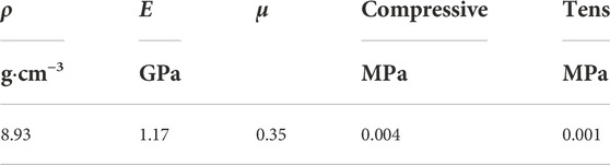
TABLE 4. Parameters of the energy-gathering pipe.
Analysis of numerical simulation results
Explosives explode in boreholes, forming explosion cavities around the boreholes. When the shock wave passes through the energy-accumulating pipe, it is compressed by the pipe, creating a jet in the direction of the energy-accumulating trough that penetrates the coal body and generates cracks.
Figures 3A–C depict that a blasting cavity forms rapidly around the borehole, and the area and stress of the blasting cavity in the energy-accumulating direction are larger than those in the non-energy-accumulating direction. Measurement of the blasting cavity area by using the measure button of LSDYNA shows that the diameter of the blasting cavity in the energy-accumulating direction is 42 cm, which is 10 times the diameter of the energy-accumulating blasting and water injection hole. The diameter of the blasting cavity in the non-energy-accumulating direction is 14 cm, which is 3.3 times of the diameter of the energy-accumulating blasting and water injection hole.
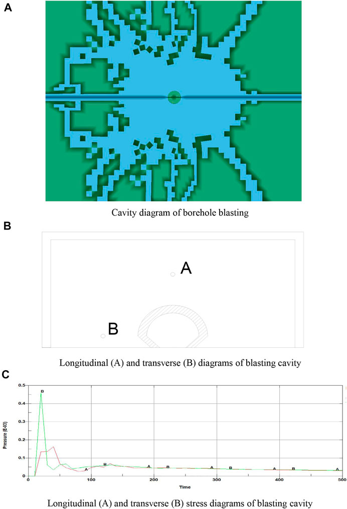
FIGURE 3. Cavity diagram of energy-accumulating blasting. (A) Cavity diagram of borehole blasting. (B) Longitudinal (A) and transverse (B) diagrams of blasting cavity. (C) Longitudinal (A) and transverse (B) stress diagrams of blasting cavity.
Two measuring points are selected in the borehole: energy-accumulating direction (horizontal) measuring point B and non-energy-accumulating direction (vertical) measuring point A. Their stress versus time diagram is output. The stress range is 0–46 MPa in the energy-accumulating direction and 0–16 MPa in the non-energy-accumulating direction. The stress in the energy-accumulating direction is 2.9 times that in the non-energy accumulating direction. Thus, the energy-accumulating pipe can effectively gather explosive explosion energy; in this direction, the coal body has large force and obvious crack propagation.
Stress waves move mainly in the direction of the energy-accumulating trough with formation of tensile stress concentration at the crack tip. The crack tip continues to expand under tensile stress. Owing to stress wave migration, fracture propagation, and the movement of coal around the fracture, the coal forms compressive stress concentration.
Figure 4 illustrates that in the energy-accumulating direction, two jets are formed by the action of the energy-accumulating trough, and the energy is greater than that in the non-energy-accumulating direction. Fracture length is measured using the measure button of LSDYNA. The fracture length in the energy-accumulating direction is 293.6 cm, and that in the non-energy-accumulating direction is 80.2 cm. That is, the fracture length in the energy-accumulating direction is 3.7 times that in the non-energy-accumulating direction.

FIGURE 4. Fracture propagation diagram.
As shown in Figures 5A–D crack is selected in the model to observe the stress changes before and after expansion. When the explosive explodes, the explosion shock wave is transmitted in the coal body to form a blasting cavity, and then the crack is expanded by the stress wave. Given that the compressive strength of coal is much greater than the tensile strength and the pressure formed by explosion is not greater than the compressive strength of coal, the coal is not damaged. When the stress tensile wave is greater than the tensile strength of coal, the tensile failure of coal extends cracks. Figure 5E shows that before the crack propagation, coal is subjected to pressure, and the peak stress is 23 MPa, which is less than the compressive strength of the coal unit. Hence, the coal crack does not expand. Under the action of tensile force, the peak stress is 8 MPa, which is greater than the tensile strength of the coal unit. Consequently, the coal unit fails, and the fracture expands.
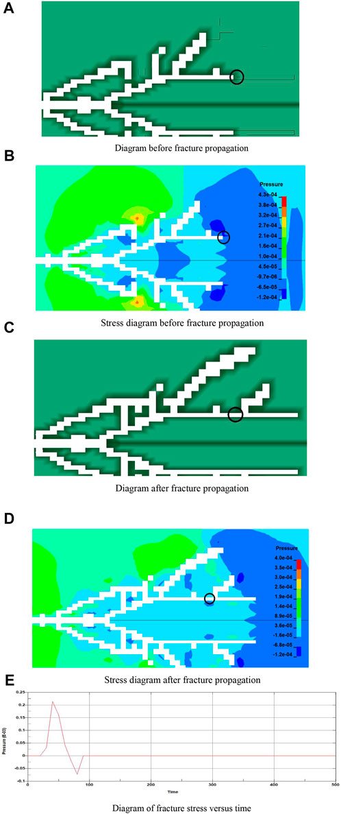
FIGURE 5. Variation diagram of local fracture propagation. (A) Diagram before fracture propagation. (B) Stress diagram before fracture propagation. (C) Diagram after fracture propagation. (D) Stress diagram after fracture propagation. (E) Diagram of fracture stress versus time.
Engineering experiment
Experimental arrangement
Energy-accumulating blasting and water injection and test holes are constructed along a coal seam at the same horizontal position of the excavation face. The interval between the blasting hole and test hole 1 is 200 cm, and the interval between each test hole and the previous test hole is 50 cm, as shown in Figure 5. To eliminate the influence of the gap in the test hole on the blasting shock wave, the depth of the latter test hole is 100 cm greater than that of the hole. The depth of the energy-accumulating blasting and water injection hole is 800 cm, that of test hole 1 is 300 cm, that of test hole 2 is 400 cm, etc. Explosives are loaded into a PVC pipe to form a “V”-shaped energy-accumulating structure, and the energy-accumulating pipe is placed horizontally (Figures 6–8).
FIGURE 6. Determination of the blasting influence radius of the working face borehole layout.

FIGURE 7. Explosive arrangement in the energy-accumulating pipe.
FIGURE 8. Principle of energy-accumulating blasting.
The energy-accumulating blasting and water injection hole uses a mud sealing hole, and the length is 200 cm. The length of the energy-accumulating pipe is 500 cm, the three-grade emulsion explosive is 5 kg, and a detonator is used. According to the research and engineering experience of scholars, the charge quantity of loose blasting is
In Eq. 11: Qs-charge quantity of loose blasting, kg; W-minimum resistance line, m.
The borehole wall of the test hole can be regarded as a free surface because the distance of the energy-accumulating blasting and water injection hole is 200 cm from the first test hole, so W is 200 cm.
Substituting the parameters into Eq. 11 leads to Qs=4.8 kg. In this experiment, the charge quantity of energy-accumulating blasting and water injection is 5 kg.
In the field experiment, due to the development of fractures around the borehole, it is not effective to fill the borehole with water, and the shock wave of shaped charge will influence the sealing effect of the test hole. Therefore, a new type of rubber bag water storage and pressure keeping device for the integration of energy-accumulating blasting and water injection and a rubber tire capsule sealing device are designed (Figure 9).
FIGURE 9. Water storage and pressure holding device.
The water storage and pressure holding device includes left rubber small bag, middle rubber large bag, and right rubber small bag. There is a certain thickness of through channel under the three bags for water circulation. The gap between the left small pocket and the middle pocket makes the energy-accumulating pipe far from the hole bottom. The gap between the right small bag and the middle bag is convenient for the loading of the energy-accumulating pipe, so that a certain distance exists between the energy-accumulating pipe and the sealing section. There are holes in the center position of the middle large bag for loading into the energy-accumulating pipe. A grouting nozzle and a shooting wire mouth exist on the right pocket for the connection of the grouting pipe and the shooting wire. Through the grouting pump, the water is filled in the whole device, and there is a certain water pressure under the action of the hole wall. The rubber bag is not permeable to obtain a good water storage effect and solve the problem that the development of borehole cracks does not allow to store water and maintain pressure. The external diameter of the water storage and pressure holding device is 4.2 cm, the length of the left bag is 50 cm, the length of the middle bag is 50 cm, the right bag is 50 cm, and the position diameter of the energy-accumulating tube is 2.4 cm (Figure 10).
FIGURE 10. Internal schematic of the blasting hole.
There is only one rubber tire bag on the sealing device, which is set on the gas drainage pipe. The grouting pipe injects the flexible gel sealing material into the tire bag through the grouting nozzle on the tire bag to seal the hole. Owing to the toughness and fluidity of the sealing device and material, when the borehole is deformed, the device can seal the borehole in real time, without air leakage gap. After the experiment, the flexible gel sealing material in the sealing bag can be released, and the sealing bag can be recycled. The length of the sealing device for testing hole sealing is 200 cm, and the diameter is 4.2 cm (Figure 11).

FIGURE 11. Internal schematic of the test hole.
Gas parameter methood
Changes in gas parameters occur in the borehole due to crack propagation after blasting. The influence range of blasting is determined by measuring the difference in gas parameters in the borehole before and after blasting. The stable drilling flow and gas concentration of each test hole are measured before blasting, and the pure amount is calculated. After blasting, the drilling flow and gas concentration of each test hole are measured every 10 min, and the pure amount is calculated. The gas parameter difference of the test hole before and after blasting is compared to determine whether the test hole is in the blasting influence range, as well as the size of the influence range, (Figure 12).
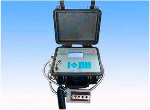
FIGURE 12. Gas parameter meter.
Result analysis
Figure 13 illustrates that before blasting of test hole 1, the borehole flow is 0.05–0.06 m3/min, and the pure quantity of gas is 0.015–0.04 m3/min; after blasting, the borehole flow is 0.08–0.09 m3/min, and the pure quantity of gas is 0.023–0.047 m3/min. Comparison of gas parameters in the borehole before and after blasting shows that the borehole flow is increased by 53.29% on average, and the pure quantity of gas is increased by 38.45% on average. With the crack propagation in test hole 1, the gas parameters change significantly.
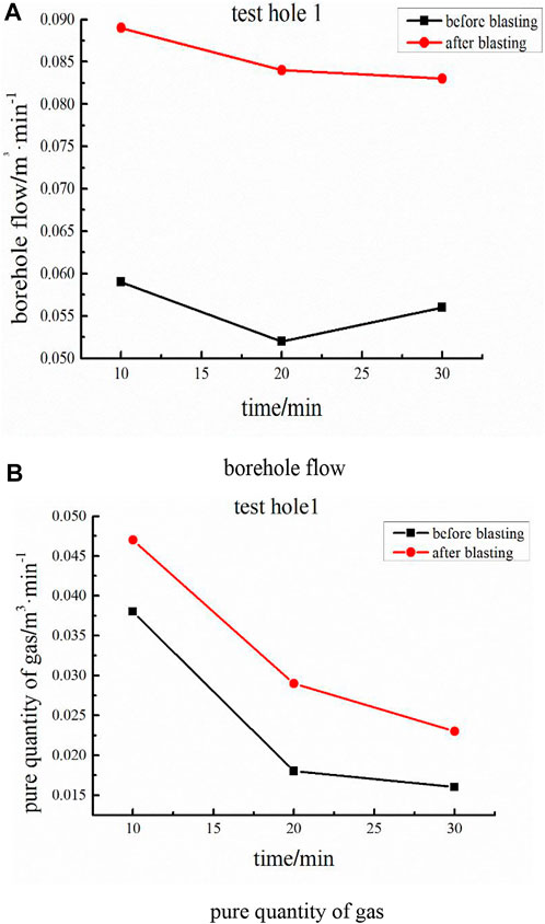
FIGURE 13. Comparison of parameters before and after blasting of test hole 1. (A) borehole flow. (B) pure quantity of gas.
Figure 14 depicts that before blasting of test hole 2, the borehole flow is 0.2–0.33 m3/min, and the pure quantity of gas is 0.06–0.095 m3/min; after blasting, the borehole flow is 0.47–0.55 m3/min, and the pure quantity of gas is 0.095–0.11 m3/min. Comparison of gas parameters in the borehole before and after blasting indicates that the borehole flow is increased by 81.09% on average, and the pure quantity of gas is increased by 26.44% on average. With the crack propagation in test hole 2, the gas parameters change significantly.
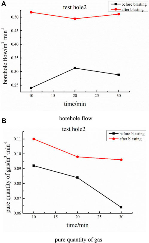
FIGURE 14. Comparison of parameters before and after blasting of test hole 2. (A) borehole flow. (B) pure quantity of gas.
Figure 15 presents that before blasting of test hole 3, the borehole flow is 0.25–0.33 m3/min, and the pure quantity of gas is 0.024–0.033 m3/min; after blasting, the borehole flow is 0.47–0.55 m3/min, and the pure quantity of gas is 0.033–0.035 m3/min. Comparison of gas parameters in the borehole before and after blasting shows that the borehole flow is increased by 75.90% on average, and the pure quantity of gas is increased by 22.63% on average. With the crack propagation in test hole 3, the gas parameters change significantly.
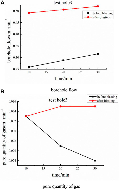
FIGURE 15. Comparison of parameters before and after blasting of test hole 3. (A) borehole flow. (B) pure quantity of gas.
Figure 16 demonstrates that before blasting of test hole 4, the borehole flow is 0.2–0.26 m3/min, and the pure quantity of gas is 0.024–0.032 m3/min; after blasting, the borehole flow is 0.21–0.28 m3/min, and the pure quantity of gas is 0.025–0.034 m3/min. Comparison of gas parameters in the borehole before and after blasting indicates that the borehole flow is increased by 7.69% on average, and the pure quantity of gas is increased by 6.25% on average. Test hole 4 is less affected by blasting, the crack propagation is weak, and the gas parameters change minimally.
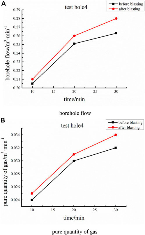
FIGURE 16. Comparison of parameters before and after blasting of test hole 4. (A) borehole flow. (B) pure quantity of gas.
Figure 17 illustrates that before blasting of test hole 5, the borehole flow is 0.023–0.027 m3/min, and the pure quantity of gas is 0.01–0.015 m3/min; after blasting, the borehole flow is 0.021–0.028 m3/min, and the pure quantity of gas is 0.01–0.016 m3/min. Comparison of gas parameters in the borehole before and after blasting shows that the borehole flow is increased by -1.32% on average, and the pure quantity of gas is increased by 3.37% on average. Test hole 5 under weak blasting stress wave action can only push coal, so that the cracks in coal are closed, cracks do not occur under coal expansion, and the drilling flow is decreased.
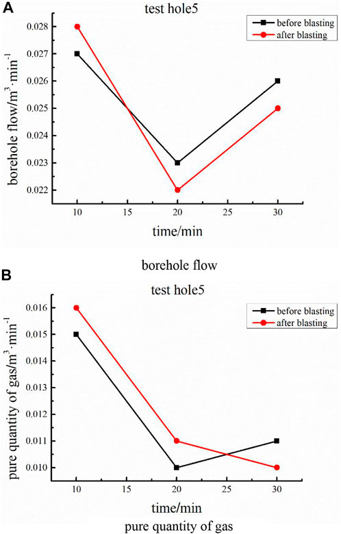
FIGURE 17. Comparison of parameters before and after blasting of test hole 5. (A) borehole flow. (B) pure quantity of gas.
Figure 18 depicts that before blasting of test hole 6, the borehole flow is 0.21–0.23 m3/min, and the pure quantity of gas is 0.033–0.056 m3/min; after blasting, the borehole flow is 0.2–0.27 m3/min, and the pure quantity of gas is 0.031–0.057 m3/min. Comparison of gas parameters in the borehole before and after blasting indicates that the borehole flow is increased by 9.39% on average, and the pure quantity of gas is increased by −1.06% on average. Blasting stress wave is not transmitted to test hole 6, and the change in gas parameters before and after blasting is not obvious.
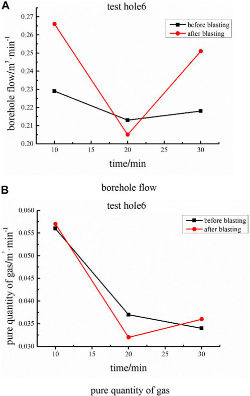
FIGURE 18. Comparison of parameters before and after blasting of test hole 6. (A) borehole flow. (B) pure quantity of gas.
In conclusion, the gas parameters of test holes 1–3 change obviously after blasting, which are in the range of blasting influence. By contrast, the gas parameters of test holes 4–6 change minimally after blasting, which are not in the range of blasting influence. Therefore, the distance from the blasting hole to test hole 3 is the influence range of energy-accumulating blasting and water injection in the direction of the energy-accumulating trough, which is 300 cm.
Engineering application
The layout of single-row-arrangement energy-accumulating blasting and water injection holes is determined in accordance with the actual situation of the Liangbei Coal Mine. The influence radius of energy-accumulating blasting and water injection is 300 cm. To prevent a blank zone, the blasting hole spacing is 550 cm. The blasting hole depth is 800 cm, the borehole diameter is 4.2 cm, the explosion hole sealing length is 200 cm, and the energy-accumulating pipe length is 500 cm, as shown in Figures 19, 20.
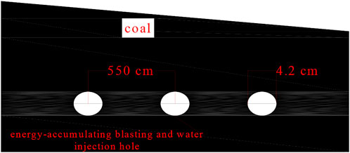
FIGURE 19. Front view of the blasting hole.
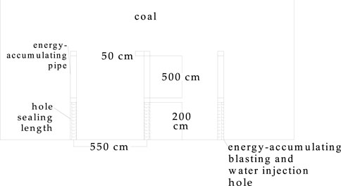
FIGURE 20. Vertical view of the blasting hole.
After the implementation of energy-accumulating blasting and water injection in the coal mining face of the Liangbei Coal Mine, the rupture and loosening of coal form a pressure relief ring, and the validation index of gas drilling declines. Comparative analysis indicates that the computed values decrease from 120–140 Pa to 100–120 Pa, and the drilling cutting weight decreases from 3.2 to 4.6 kg/m before the test to 3.0–3.8 kg/m. The permeability of blasting coal is improved. After the test, the methane concentration in the roadway increases obviously but does not exceed the standard. The water injection volume is effectively improved, and the dust is significantly reduced during tunneling. The single hole water injection is 0.1–0.7 m3, with an average of 0.5 m3. Compared with the water content in the original coal seam, the water content in the blasting area is increased from 1.26%–1.45% to 2.35%–2.75%, which effectively improves the mechanical properties of coal.
Conclusion
(1) The borehole is impacted by the shock wave of explosives, forming a blasting cavity. The diameter of the blasting cavity in the energy-accumulating direction is 42 cm, which is 10 times of the diameter of the circular hole. The diameter of the blasting cavity in the non-energy-accumulating direction is 14 cm, which is 3.3 times of the diameter of the circular hole. The stress range in the energy-accumulating direction is 0–46 MPa, and that in the non-energy-accumulating direction is 0–16 MPa. That is, the stress in the energy-accumulating direction is 2.9 times that in the non-energy-accumulating direction. Hence, the energy-accumulating pipe can effectively gather explosive energy.
(2) Fracture length is measured using the measure button of LSDYNA. The fracture length in the energy-accumulating direction is 293.6 cm, and that in the non-energy-accumulating direction is 80.2 cm. That is, the fracture length in the energy-accumulating direction is 3.7 times that in the non-energy-accumulating direction.
(3) Theoretical analysis and calculation indicate that the crushing area of shaped charge blasting is 39 cm, the fracture area is 267 cm, and the vibration area is 159 cm.
(4) Comparison of gas parameters before and after blasting by using a gas parameter meter shows that the gas parameters of test holes 1–3 change obviously after blasting and are in the range of blasting influence. On the contrary, the gas parameters of test holes 4–6 change minimally after blasting and are not in the range of blasting influence. The distance between the energy-accumulating blasting and water injection hole and test hole 3 is determined as the influence radius of the energy-accumulating blasting and water injection process. Through numerical simulation, theoretical analysis, and field experiments, the influence radius of directional pressure relief of energy-accumulating blasting and water injection in the Liangbei Coal Mine is determined to be 300 cm.
Data availability statement
The original contributions presented in the study are included in the article/supplementary material, further inquiries can be directed to the corresponding author.
Author contributions
ZW proposed the research. YW prepared the figures and tables and interpreted the test and data. All authors have read and agreed to the published version of the manuscript.
Acknowledgments
The authors appreciate the comments and suggestions by the editors and reviewers. This work is supported by the State Key Laboratory Cultivation Base for Gas Geology and Gas Control (WS2021B07).
Conflict of interest
The authors declare that the research was conducted in the absence of any commercial or financial relationships that could be construed as a potential conflict of interest.
Publisher’s note
All claims expressed in this article are solely those of the authors and do not necessarily represent those of their affiliated organizations, or those of the publisher, the editors and the reviewers. Any product that may be evaluated in this article, or claim that may be made by its manufacturer, is not guaranteed or endorsed by the publisher.
References
Cao, H., Jiang, C-L., and Zang, P. (2013). Feasibility analysis of loose blasting outburst prevention mechanism based on spherical shell instability theory. [J].Safety Coal Mines 44 (01), 153–156.
Dou, L-M., He, X-Q., and Ren, T. (2018). Mechanism of coal-gas dynamic disasters caused by the superposition of static and dynamic loads and its control technology[J]. J. Of China Univ. Of Min. And Technol. 47 (01), 48–59.
Gao, X-Y., Liu, J., and Zhang, C. (2019). Experimental study on permeability Improvement of deep hole pre splitting cumulative blasting in low permeability coal seam. J.Safety Coal Mines 50 (04), 23–26+31.
Guo, D-Y., Zhang, C., and Li, K. (2021). Mechanism ofmillisecond-delay detonation on coal cracking under deep-hole cumulative blasting in soft and low permeability coal seam[J/ol]. J. Of China Coal Soc., 1–10.
Guo, D-Y., Zhao, J-C., and Lv, P-F. (2019). Effective fracture zone under deep-hole cumulative blasting in coal seam[J]. Chin. J. Of Eng. 41 (05), 582–590.
Guo, D-Y., Zhao, J-C., and Zhu, T-G. (2020). Crack propagation and coalescence mechanism of double-hole cumulative blasting incoal seam[J]. Chin. J. Of Eng. 42 (12), 1613–1623.
Hua, X-Z., Liu, X., and Huang, Z-G. (2020). Stability mechanism of non-pillar gob-Side entry retaining by roof cutting under the coupled static-dynamic loading[J]. J. Of China Coal Soc. 45 (11), 3696–3708.
Huang, B., and Li, P. (2015). Experimental investigation on the basic law of the fracture spatial morphology for water pressure blasting in a drillhole under true triaxial stress. Rock Mech. Rock Eng. 48 (4), 1699–1709. doi:10.1007/s00603-014-0649-y
Huang, B., Liu, C., Fu, J., and Guan, H. (2011). Hydraulic fracturing after water pressure control blasting for increased fracturing. Int. J. Of Rock Mech. And Min. Sci. 48 (6), 976–983. doi:10.1016/j.ijrmms.2011.06.004
Kim, D-G. (2007). A study on notch bit system for controlling blast vibration and over-break in rock mass [J]. Tunn. And Undergr. Space 17 (3), 216–224.
Lan, Y-W., Gao, H-M., and Chen, X-H. (2013). Numerical simulation study on influence factors of borehole pressure relief effect[J]. Min. Saf. And Environ. Prot. 40 (03), 6–9.
Li, B., Shi, Z., Li, L., Zhang, J., Huang, L., and He, Y. (2022). Simulation study on the deflection and expansion of hydraulic fractures in coal-rock complexes. Energy Rep. 8, 9958–9968. doi:10.1016/j.egyr.2022.07.174
Li, B., Zhang, J., Liu, Y., Qu, L., Liu, Q., Sun, Y., et al. (2022). Interfacial porosity model and modification mechanism of broken coal grouting: A theoretical and experimental study. Surfaces And Interfaces 33, 102286. doi:10.1016/j.surfin.2022.102286
Liu, H-G., He, Y-N., and Xu, J-H. (2007). Numerical simulation and industrial test of boreholes destressing technology in deep coal tunnel[J]. J. Of China Coal Soc. (01), 33–37.
Liu, Y-K., Liu, C., and Ding, J-X. (2012). Study and application on destressing and elimination outburst technology in LargeDiameter hole[J]. Saf. Coal Mines 43 (02), 82–84.
Song, Y-Q., Li, X-S., and Guo, D-Y. (2018). Numerical simulation of multi-hole and same delaytime of cumulative blasting in coal seam and its application[J]. J. Of China Coal Soc. 43 (S2), 469–474.
Tan, D-Y. (2011). Research of heterogeneous drill rod and craft technology of construction for soft-extrude coal along level bed[J]. Coal Mine Mach. 32 (04), 220–222.
Wei, M-Y., Wang, E-Y., and Liu, X-F. (2011). Numerical simulation of rockburst prevention effect by blasting pressure relief in deep coal seam[J]. Rock And Soil Mech. 32 (08), 2539–2543+2560.
Yang, J-H., Hu, D-R., and Zhu, C-H. (2019). Study on numerical simulation on shaped charge blasting parameters of Peripheral holes[J]. Coal Sci. And Technol. 47 (01), 187–192.
Yuan, W., Wang, W., and Su, X. (2019). Experimental and numerical study on the effect of water-decoupling charge structure on the attenuation of blasting stress [J]. Int. J. Of Rock Mech. And Min. Sci. 124. doi:10.1016/j.ijrmms.2019.104133
Yuan, W., Wang, W., and Su, X. (2018). Numerical study of the impact mechanism of decoupling charge on blastingenhanced permeability in low-permeability sandstones [J]. Int. J. Of Rock Mech. And Min. Sci. 106 (300-10). doi:10.1016/j.ijrmms.2018.04.029
Zhai, H. (2010). An experimental study on A permeability improvement and pressure relieving technology by energy cumulative blasting in steeply inclined boreholes made upward through rock and coal seam[J]. Chinacoal 36 (04), 86–89.
Zhang, J., Li, B., and Liu, Y. (2022). Dynamic multifield coupling model of gas drainage and A new remedy method for borehole leakage [J]. Acta Geotech., 1–17.
Zhang, J., Liu, Y., Ren, P., Han, H., and Zhang, S. (2021). A fully multifield coupling model of gas extraction and air leakage for in-seam borehole. Energy Rep. 7, 1293–1305. doi:10.1016/j.egyr.2021.02.037
Zhang, S., Wang, X-L., and 'Zhao, W-F. (2019). Study on application of D-type energy gathering blasting tube on gob-side entry retaining[J]. Coal Sci. And Technol. 47 (10), 175–182.
Keywords: energy-accumulating blasting, water injection, energy-accumulating pipe, gas parameter meter, variation in gas parameters, radius of influence
Citation: Wang Z, Wang Y and Wang F (2023) Influence radius of pressure relief of energy-accumulating blasting and water injection in the heading face of the liangbei coal mine. Front. Earth Sci. 10:1026816. doi: 10.3389/feart.2022.1026816
Received: 24 August 2022; Accepted: 13 September 2022;
Published: 05 January 2023.
Edited by:
Guangyao Si, University of New South Wales, AustraliaReviewed by:
Junxiang Zhang, Zhongyuan University of Technology, ChinaJingyu Jiang, China University of Mining and Technology, China
Tao Yang, North China Institute of Science and Technology, China
Copyright © 2023 Wang, Wang and Wang. This is an open-access article distributed under the terms of the Creative Commons Attribution License (CC BY). The use, distribution or reproduction in other forums is permitted, provided the original author(s) and the copyright owner(s) are credited and that the original publication in this journal is cited, in accordance with accepted academic practice. No use, distribution or reproduction is permitted which does not comply with these terms.
*Correspondence: Yu Wang, MjQ3MTgwNTI4NUBxcS5jb20=