- 1School of Energy Science and Engineering, Henan Polytechnic University, Jiaozuo, China
- 2Collaborative Innovation Center of Coal Work Safety and Clean High Efficiency Utilization, Jiaozuo, China
- 3School of Safety Engineering, China University of Mining and Technology, Xuzhou, China
- 4Industrial Technology Research Institute, Henan Polytechnic University, Jiaozuo, China
The technology described as gob-side entry driving was adopted in the Zhaogu No. 1 mine to resolve the issues pertinent to mining succession tension, serious roadway deformation, and support difficulties. The key parameters of coal columns must be studied to ensure the stable support effect of along-air tunneling under high stress. A calculation for the vertical stress of a coal pillar is proposed, and the location of the breaking line in the top plate in the hollowed mining zone is determined by considering the breakage attributes of the basic uppermost large structure of the key layer, combined with the internal and external stress fields, and the limit equilibrium zone theories. FLAC3D software is employed to simulate the geological requirements of the mine, the characteristics of vertical stress of the coal pillar, and the surrounding rock of the roadway under the technical plan of leaving a 4.5-m coal pillar. The software is also used to verify and analyze the actual measurements. The outcomes suggest that the basic roof break is located at 2.65 m on the side of the coal pillar in the near mining area, and there is a trapezoidal internal stability region around the coal pillar that can provide lasting and stable support of the roadway. The displacement of the two helpers of the roadway is between 100 and 500 mm, and the displacements of the top and bottom plates are less than 300 mm, which ensures the roadway is surrounded by rock when the high-stress requirements occur. The safety of the roadway is determined under high-stress conditions.
Introduction
With increasing depth, underground coal mining causes the mining roadway to be affected by high stress after tunneling, which makes the surrounding rock unstable and the roadway deformation problem prominent. To improve the resource recovery rate of coal mining and slow succession tensions of mining, many mines have recently promoted the technology called gob-side entry driving (G-SED) in coal tunneling operations (Wang, 2012; Xu et al., 2015; Zhang, 2019). To solve the application problems of G-SED technology under high-stress conditions, research on the control of surrounding rock under high stress has become the focus of engineering research.
Several researchers have recently examined the deformation and damage process and its technology to control the rocks surrounded by the G-SED technology (Liu, 2017; Sun, 2019; Wang, 2016; Zhang, 2020). Zhang et al. (2019) researched and analyzed the mechanical evolution mechanism of coal rupture in the roof slab of the G-SED and proposed corresponding countermeasures. Li Xuehua et al. (Li et al., 2016) ran simulations that summarized and analyzed the factors influencing the deformed and damaged narrow coal pillars of the G-SED and studied the influence of different factors on their stability. He Fulian et al. (He and Zhang, 2015) derived an equation to identify the position where the peak tendency support pressure of the comprehensive caving working face is located, which provides an important reference for deriving reasonable parameters of the coal pillar of the header working face roadway protection. Li Jucai et al. (Jiang et al., 2014; Wang et al., 2019) studied and analyzed the evolution law of the fissure of the surrounding rocks in the G-SED and the force characteristics of the surrounding rocks at the coal pillar side. Zheng et al. (2012) run a simulation to investigate the relationship between the deformation of the rocks surrounded by the roadway, the anchor support’s strength, the stability of the coal pillar, and the coal pillar’s width in the G_SED.
Within this process, the characteristics of the stress variation for the rocks surrounding the tunnel and coal pillar retention parameters are crucial. For example, studies have examined the distribution of the stress and the characteristics of the deformation that occurred on the top rock layer, retained coal pillars, and solid coal side (Shi et al., 2004; Xie et al., 2002). The retention parameters need to consider the strength, bearing capacity, and applicability of the coal pillars (Xiaofei et al., 2020). The Holland–Gaddy formula (Golasowski et al., 2014) theoretical calculation, the empirical formula Obert–Dwvall/Wang formula (Tian et al., 2016), numerical simulation (Hu et al., 2012; Zhu et al., 2011), and other methods have been used to analyze the destabilization damage mode of retained coal pillars, reveal the destabilization mechanism of the top plate, left-in coal pillars, and the half arch of the cemented slab along the hollow boring (Jia and Hu, 2020), and make a remarkable contribution to the understanding of the left-in coal pillars.
The complex situation of the G-SED varies with the different geological conditions of coal mines, and limited research has investigated the mechanical characteristics of the G-SED under high-stress conditions in deep mines. Taking the Zhaogu No. 1 Coal Mine of the Jiaozuo Coal Group as an example, the dynamic change process of roadway instability and the mechanical attributions of coal pillar for the G-SED were studied, and the corresponding surrounding rock control technology and support scheme were proposed. This example enables us to observe the deformation that occurred on the surrounding rock of the roadway in the researched zone.
The background of the engineering
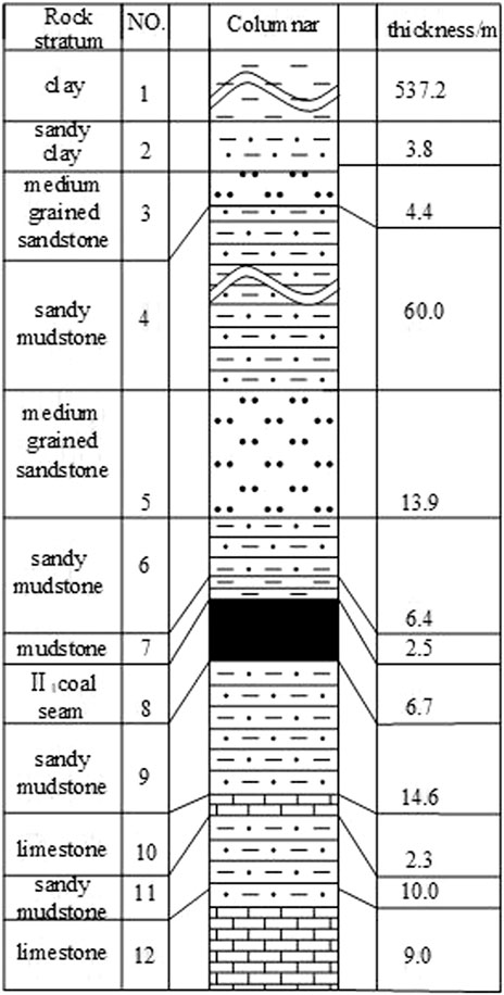
The coal seam II1 of the Zhaogu No. 1 Coal Mine of Jiaozuo Coal Group is now mined. The depth of the mine is about 630 m, and the loess coating cover is 537.2 m. The coal seam occurs stably. The thickness is between 6.4 and 7.1 m, and the dip angle is 4°–6°. The hardness f of coal and rock strata is 1–2. The natural tendency of the coal seam is not prone to spontaneous combustion, and the ground pressure is large. The original gas content is 3.59 m3/t. Figure 1 depicts the comprehensive histogram of the working face.
Figure 1 shows that the upper structures of the II1 coal seam (6.7 m) are clay (537.2 m), sandy mudstone (3.8 m), medium sandstone (4.4 m), sandy mudstone (60.0 m), medium sandstone (13.9 m), and sandy mudstone (6.4 m). The lower structures are sandy mudstone (14.6 m), limestone (2.3 m), sandy mudstone (10 m), and limestone (9 m).
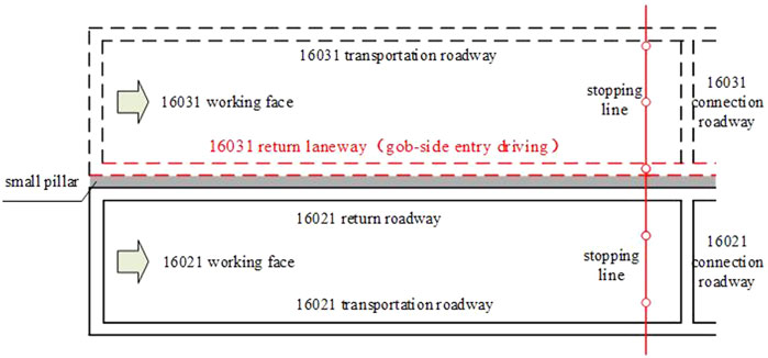
The working face numbered 16021, located in a horizontal upper stratified sixth-panel area on the Northeast side of the minefield, was studied. The western part is the 16011 goaf, and the eastern part is the planned 16031 working face, which is a typical high-stress working face. The northern part is solid coal, and the southern part is the north return air roadway of the mine, as shown in Figure 2. The G-SED is designed in the lower trough of the 16031 working face as the return air roadway. 16021 is now goaf, and the roof of the goaf is treated by the whole caving method.
Fracture characteristics of rock roof
Roof breaking process
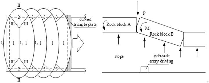
From the perspective of the goaf mechanics, when the upper section of the working face is mined from the open-off cut to the first weighting, the parallel fracture lines I1 and I2 were formed in the center of the exposed main roof and the centers of the two long sides, and then the fracture line II was formed in the short side, and it was connected with the fracture lines I1 and I2 to form an “O” fracture. Finally, the basic roof strata rotated along fracture lines I and II to form fracture line III, and an “X” fracture occurred. After the fracture, blocks 1 and 2 were formed. The working face continued to advance, and the roof periodically caved, followed by fracture lines I2 and II. Surrounding fracture line I2, a III rotation caused periodic roof caving, and the basic roof formed new structural blocks 1 and 3. This process is shown in Figure 3.
Driving mining vehicles on the working face roadway along the goaf and mining of the working face will cause instability of the basic roof. The rock mass A is affected by the rotation torque M′ and M and tends to turn and sink at the position of arc triangle B. The large structure balance of the driving roadway along the goaf is broken. At this time, the surrounding rocks are unstable, and the roof loses support, resulting in movement and deformation of the strata above the goaf.
Because the fractured site of the roof at the edge of the goaf is impacted by many attributes, such as rock occurrence, the mechanical features of the surrounding rock, the working face advancing speed, mining height, buried depth, and stope and roadway support, the post of the fractured line of the roof at the edge of the goaf is uncertain. In addition, the stress characteristics of the rock surrounded by the roadway along the goaf corresponding to different fracture lines are different.
Calculation of fracture line position
The theoretical results of the internal and external stress fields show that, with the fracture line as the boundary, the stress was transferred from the overlying strata to the coal seam, and the key block was divided into internal and external stress. The basic roof breaks after reaching the fracture step distance, and the collapsed basic roof is the main support pressure source in the S1 area of the internal stress field. The supporting pressure generated in the area of external stress field S2 mainly comes from the self-weight of the overlying strata. Figure 4 depicts the distributional cross-section fields related to internal and external stresses.
The field distance of the internal stress S1 is computed by (Song, 1988)
where L denotes the length of the working face, L = 180 m;L1 is the first roof weighting step, L1 = 28.7 m; Sp is the influence range of advanced pressure, Sp = 18 m; H is the thickness of arc triangle, h = 13.9 m; K represents the coefficient of the stress concentration, K = 1.4; H denotes the depth of roadway, H = 628 m.
The above field measurement values are substituted into Eq. 1, S1 = 2.65 m. That is, the post of the basic top fracture line is 2.65 m from the goaf flank of the coal pillar.
Calculation of vertical pressure of coal pillar
Induction of vertical stress model of coal pillar
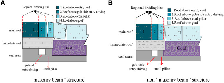
The large structure of the broken top can be divided into masonry beam and non-masonry beam structures. The key structural difference between the masonry beam and the non-masonry beam structures is that the fault block under the masonry beam structure squeezes the new roof after fracture due to mutual rotation. Accordingly, the new roof coupled with the broken roof leading to a newly formed structure impacts the coal pillar left in the G-SED. The fault block was separated from the new roof when the non-masonry beam structure was under consideration. The vertical stress pertinent to the fault block and the new roof on the coal pillar can be regarded as the respective action of two independent components. Due to the different positions of the fracture lines of the basic roof, the two models can be classified into four different fracture types: the fracture lines are located above the entity coal, above the G-SED, and above both the coal pillar and the goaf. When the position of the fracture line or the condition of mechanical balance varies, the vertical stress of the coal pillar will also change, as shown in Figure 5.
Without human intervention, the migration of the basic roof is a relatively slow process after the breaking trend occurs. The collapse mode of the broken roof (rock block B) is the rotary collapse in Figure 5A, and the masonry structure will inevitably form between the broken roof (rock block B) and the stable roof (rock block A).
Analysis of the vertical stress related to the coal pillar
Considering the comprehensive geological conditions, the 4.5-m narrow coal pillar roadway protection technology is selected in this mine. According to Eq. 1 and the field data calculation results, the fracture line is located at 2.65 m near the goaf side above the solid coal; that is, the fracture line is located above the coal pillar, and a masonry beam structure is formed between rock blocks. The mechanical model is shown in Figure 6.
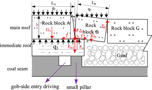
FIGURE 6. Diagram of the vertical stress mechanical model of a coal pillar. Physical quantity annotation: q1, overburden load on rock block A, MPa; q2, the support load of the direct roof to block A, MPa; q3, loading of overlying strata on rock block b, MPa; LA, length of rock block A, m; LB, length of rock block B, m; GA, the weight of rock block A, N; GB, self-weight of rock block B, N; FBA, the vertical force of rock block B on A, N; FCB, vertical force of rock block C on B, N; Fm, the stress transferred from the basic top to the coal pillar, N; FC, the stress transmitted by the gangue in the goaf to the rock block B, N; XA, the distance between the load force position transmitted by rock block A to coal pillar and the right end of rock block A, m; XB, the distance between the load force position transmitted by rock block B to coal pillar and the left end of rock block B, m; t, the horizontal force between block A, B, and C, N; θ − rotation angle of rock block B, °; h, the thickness of rock blocks A, B and C, m.
The rock mass of the basic roof far from the roadway is not destroyed, so a rock block called A can be regarded as a cantilever beam structure. The upper part is subjected to the uniform load q1 of the overlying strata. The lower part is subjected to the support load q2 of the direct roof and a force of the rock to block B and the support pressure of the coal pillar Fm. The rock blocks A and B sink synchronously at the occlusal point O1, and the load Fm transferred from the basic top to the coal pillar under the mechanical structure is obtained by solving the vertical settlement. Because AB forms a masonry beam structure, the supporting force on the left side of rock block B is provided by rock block A. As a result, the coal pillar does not directly affect rock block B.
As the principles of material mechanics and mechanical equilibrium analysis suggest, the stress analysis related to important rock blocks A and B is as follows.
(1) Analysis of rock block A
The subsidence of rock block A under the action of uniform load q1, q2, and self-weight GA is:
The subsidence of rock block A when the coal pillar has load Fm is:
The decrease of rock block A under the action of rock block B force FBA to is:
Therefore, the overall subsidence of point O1 at the intersection of rock blocks A and B is:
Taking vertical pressure Fm of coal pillar as the independent variable,
(2) Analysis of rock block B
The static equilibrium equations of the x direction and the y direction and the moment equilibrium equations of point O1 and point O2 are listed below:
Inserting Eq. 6yields:
In the formula, q1 is the rock load on block A, q1 = 1.2 × 10⁷ Pa; q2 is the support load of the direct roof to block A, q2 = 1.04 × 10⁷ Pa; q3 is the overburden load on block B, q3 = 6.9 × 10⁶ Pa; LA denotes the length of block A, LA = 200 m; LB represents the length of block B, LB = 5.7 m; GA denotes the weight of rock block A, GA = 7.01 × 10¹⁰N; GB represents the weight of rock block B, GB = 2.0 × 10⁹N; x represents the distance between the joint force position of the coal pillar and the right end of rock block A, x = 1.85 m; θ denotes the rotation angle of rock block B, θ = 16.6°; h represents the thickness of block A, B, C, h = 13.9 m; E is rock elastic modulus, E = 3.49 × 10⁹Pa; I is the moment of inertia of rock block A, I = 2.6 × 10⁶ m4, ω is the overall subsidence of rock blocks A and B after occlusion, ω = 0.15 m.
The coal pillar vertical pressure Fm = 2.27 × 10¹⁰ N, the coal pillar width is 4.5 m, the roadway strike length is 970 m, and the coal pillar vertical stress uniform load is 5.2 MPa.
The model in this paper considers the large structural fracture of the key strata in the roof of the goaf. For rock block B, the periodic fracture along the advancing direction of the working face will produce small blocks. The interaction between small blocks is not the focus of this study.
The characteristics of the vertical stress related to the coal pillar
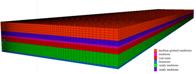
The deformation attributes of the rock surrounding the roadway when a small coal pillar was created were numerically simulated by FLAC3D software, and the distribution characteristics of the vertical stress for the coal pillar when the key strata are considered were analyzed. A Mohr–Coulomb model was constructed according to the determination of the research object and the simulation scheme. The model size was 200 m * 911 m * 46.4 m. In the numerical calculation, the movements of the model are constrained horizontally and vertically. A vertical stress of 12 MPa is implemented on the upper bound in the model to simulate the gravity of the overlying strata. The horizontal lateral pressure coefficient λ is selected as 1.6, and the coal seam and key layer roof and floor physical and mechanical parameters are shown in Table 1. The width of the coal pillar is set to 4.5 m, the width of roadway excavation is set to 4.7 m, the height is set to 3.5 m, the section shape is rectangular, and the excavation method is a step excavation with a 150-m range. The model is shown in Figure 7.
Vertical stress distribution of coal pillar
Figure 8A shows the stress distribution characteristics of the roadway under the action of vertical stress. The small coal pillar located in the stress reduction zone can be seen fairly. At this time, concentrated stress is generated within the coal pillar, and the body of coal near the side of the roadway by the coal pillar is plastically damaged and gradually unloaded; however, the prop support capability of the coal pillar has not altered substantially.
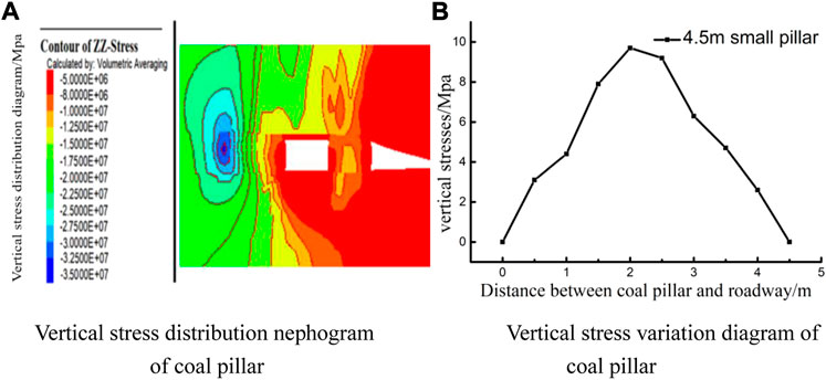
FIGURE 8. Coal pillar vertical stress distribution diagram. (A) Vertical stress distribution of the coal pillar. (B) Vertical stress variation diagram of the coal pillar.
The vertical stress on the solid coal side first increases and then decreases. The peak stress is at 6 m in the shallow part of the firm coal side of the G-SED, and the peak value is about 35 MPa. The stress was concentrated in a “butterfly wing” type distribution.
Figure 8B depicts the distribution of the vertical stress for the coal pillar. Under the premise of a 4.5 m coal pillar simulation, an increasing trend followed by a decreasing trend is observed in the vertical stress in the direction in which G-SED is applied to the goaf, and the impact interval is in the shallow part of the surrounding rock. The peak vertical stress value of the coal pillar, 9.2 Mpa, is reached at the 2.2 m depth within the roadway surface. Besides, the whole shallow surrounding rock area is characterized by “trapezoidal distribution”. In the area of 2.2–2.8 m, the diminishing ratio of the coal pillar stress slows, which indicates that there is a stable area of vertical stress, and the middle part of the coal pillar becomes stable. Therefore, this area has a stable coal pillar. If the uniform load in the overall interval of the coal pillar is considered, the uniform load after integration is 5.9 MPa.
Field practice
Roadway support
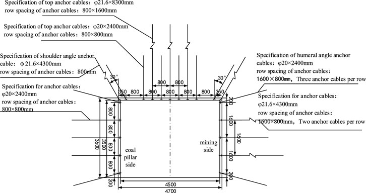
The roadway layout by G-SED technology needs to wait for the stabilization of the surrounding rock in the goaf. Roadway support strength must be improved to assure the protection of the roadway during excavation and mining. The roadway support scheme uses the combined support of bolts, JW is a steel strip model, steel strips in the form of a W, combined anchor cables, and metal mesh. The roadway was sprayed and reinforced in the early stage to suppress the gas leakage in the goaf of the 16021 working face. Later, it was sprayed and reinforced again to strengthen the rock structure surrounded by the roadway and inhibit the subsidence of the top layer under the action of mining. Figure 9 depicts the supporting section.
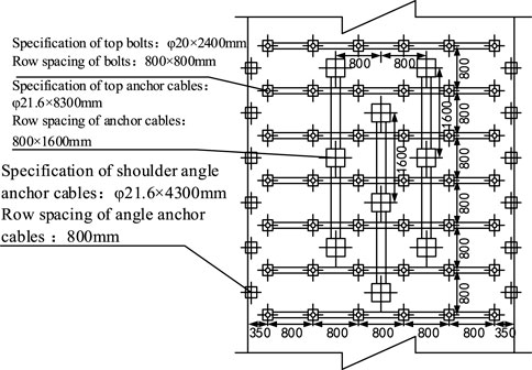
Roadway roof support: An anchor net and cable belt are responsible for supporting the roof, and ø20 mm × 2,400 mm high-strength left spiral steel bolts with no longitudinal reinforcement are used. One row of anchor cables is punched for every two rows of anchor bolts, and the JW high-strength steel belt and metal net mesh are suspended by anchor cables. A row of composite anchor cables (ø21.6 mm × 8 300 mm) was arranged in the middle of each two rows of bolts. The composite anchor cable was arranged vertically by 400 mm × 400 mm × 16 mm high strength pallets and supporting locks. The shoulder-angle anchor cables of ø21.6 mm × 8 300 mm and ø21.6 mm × 4 300 mm are arranged at the roof shoulder-angle mumps, with an inclination angle of 50°. The anchor cable is suspended with a 600 mm short-section I-steel, and the anchor cable tray is a 200 mm × 200 mm × 12 mm high-strength spherical tray. The roof support is shown in Figure 10.
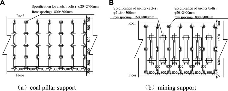
The support of two sides of the roadway: the coal pillar side is supported by an anchor net, and ø20 mm × 2,400 mm high-strength bolts without longitudinal reinforcement were selected. The roof angle bolts are 200 mm from the roof and inserted at a 15° upward angle with a guide gasket. The bottom angle bolts are 200 mm from the floor of the roadway and inserted at a 15° downward angle with a guide gasket. Other bolts are perpendicular to the coal wall. A 150 mm × 150 mm × 10 mm high-strength arch anchor tray, W-shaped steel plate (560 mm × 280 mm × 6 mm), and the metal mesh protection table were selected. Figure 11A depicts the support of the coal pillar. The mining side is supported by bolt-mesh-cable, and ø20 mm × 2,400 mm high-strength bolts without longitudinal reinforcement were selected. The roof angle bolts are 200 mm from the roof and inserted at a 15° upward angle with a guide gasket. The bottom angle bolts are 200 mm from the floor of the roadway and inserted at a 15° downward angle with a guide gasket. Other bolts are perpendicular to the coal wall. A 150 mm × 150 mm × 10 mm high strength arch anchor tray, W-shaped steel belts (3,600 mm × 280 mm × 3.75 mm), and a metal mesh protection table were selected. The ø21.6 mm × 4 300 mm short anchor cable was selected to be constructed in parallel with the anchor bolt. The 200 mm × 200 mm × 16 mm steel plate was selected as the anchor cable tray, and a 200 mm × 200 mm × 50 mm wood plate was sandwiched between the plate and the plate. The support of the mining side is shown in Figure 11B.
Displacement surveying of wall rock
The cross observation method was utilized to test the surface dislocation of the surrounding rock. The measuring points of the two sides of the 16031 return airway are located in the middle section of the roof and floor of the roadway, and the measuring points of the roof and floor are away from the side of the coal pillar and the middle of the firm coal.
In the 16031 gob-side entry driving 0–300 m, a measuring point will be laid out every 150 m, identified as A-C. The effect of the mining operation will be fully considered when the working face advances beyond the measuring point. Each observation will be recorded, and statistical analysis will be performed on the observation results.
Figure 12 depicts the alteration of the surrounding rock displacement related to each test point during the observation period. In measurement points A, B, and C, the roof subsidence is obvious in the early stage of observation, and then the subsidence gradually stabilizes. The roof subsidence is between 0 and 150 mm, which is in the allowable deformation range when the observation is conducted.
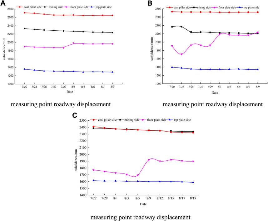
FIGURE 12. Displacement variation of the surrounding rock at each measurement point. (A) Measuring point roadway displacement of “A”. (B) Measuring point roadway displacement of “B”. (C) Measuring point roadway displacement of “C”.
By comparing the displacement of the floor of the three points, it can be seen that the subsidence of the floor can be stabilized at the later stage of observation. The analysis data are obtained at the bottom plate of measuring point A, and attention must be paid to preventing accidents. The bottom excavation phenomenon in the observation period of measuring point B occurred twice, but the floor gradually stabilized in the late observation period. There was a bottom excavation phenomenon in the observation period of measuring point C. In the late observation period, there was no continuous stable stage in the floor. However, the roadway formation was stable because the floor observation position was damaged by construction on August 15, and the displacement was affected by the relocation of measuring points. During the observation period, the floor displacement finally stabilized, and the displacement variation was between 200 and 500 mm, which is in the allowable deformation range.
Compared with the displacement change of the three points, the displacement change of the mining side is more obvious in the early stage of the observation. This is a normal phenomenon after the roadway excavation and pressure, and the support observation in the three directions of the roadway gradually stabilizes in the later stage. During the observation period of the three-point roadway, the displacement variation is between 100 and 200 mm, which is in the allowable deformation range.
To summarize the deformation characteristics of roadway surrounding rock displacement, the displacement of the rock surrounding the roadway changes little at the beginning of excavation. With the deepening of the excavation, the displacement of the floor begins to rise, which is the result of the transfer of the surrounding rock pressure on the other three sides to the floor due to the support effect. After the roadway is formed, the displacement of surrounding rock can stabilize, indicating that the support measures can achieve the desired results.
Summary
Internal and external stress field models are constructed to analyze the fracture position of the key roof layer and determine whether the 4.5 m coal pillar retained by G-SED technology when geological conditions are described as high stress can achieve the requirement of roadway stability maintenance. The vertical stress value of the coal pillar under the roadway stability is attained by theoretical calculation. FLAC3D software was used to simulate the vertical stress distribution law of the coal pillar under this condition. Finally, the roadway stability is analyzed through field measurement, and the following conclusions are obtained:
(1) The basic roof fractured at 2.65 m from the coal wall side of the goaf. Using the principles of material mechanics, the vertical stress for the 4.5-m coal pillar left under the basic roof fracture was mechanically deduced. The theoretical uniform stress was 5.22 MPa. The roof parameters of the working face were used for numerical simulation, and a stress of 5.9 MPa was uniformly applied to the coal pillar. The mechanical simulation results are close to the numerical simulation results, and the correspondence between the two values is good, indicating that the theoretical model under high stress can reflect the fracture characteristics of the roof.
(2) The actual geological requirements of the mine include unstable features of the surrounding rock, control of the G-SED, and high stress. Therefore, a combined support scheme of bolts, JW-type high-strength steel strips, steel strips in the form of a W, combined anchor cables, and metal mesh was adopted to assist the grouting treatment in strengthening the roadway. The cross observation method was utilized to monitor the displacement occurring on the side surface of the roadway. The monitoring results show that the distortion of the roadway is within the allowable range, and the overall structure is stable. This support condition can satisfy the safe mining conditions of the working face.
Data availability statement
The original contributions presented in the study are included in the article/supplementary material. Further inquiries can be directed to the corresponding authors.
Author contributions
WW: conceptualization, methodology, and software. YW: data curation, writing—original draft, and preparation. XL: writing—reviewing and editing. GZ: validation.
Funding
Supported by the Program for Innovative Research Team (in Science and Technology) of the University of Henan Province (22IRTSTHN005); Henan Province Science and Technology Project, 212102310603; Research on Stability Characteristics and Key Reinforcement Technology of Coal Pillar Dam under Complex Stress and Water Immersion; Henan University Young Backbone Teacher Training Program, 2019GGJS053, Study on damage and energy dissipation of coal samples under true three-dimensional dynamic and static combined; Innovative Research Team of Henan Polytechnic University, Study on Mechanism and Disaster Warning of Coordinated Exploitation of Coal and Natural Gas in Ordos Basin; Henan University Science and Technology Innovation Talent Support Plan, natural gas and coal resources superimposed area coordinated mining theory and key technology research, 23HASTIT011.
Conflict of interest
The authors declare that the research was conducted in the absence of any commercial or financial relationships that could be construed as a potential conflict of interest.
Publisher’s note
All claims expressed in this article are solely those of the authors and do not necessarily represent those of their affiliated organizations or those of the publisher, the editors and the reviewers. Any product that may be evaluated in this article, or claim that may be made by its manufacturer, is not guaranteed or endorsed by the publisher.
References
Golasowski, J., Vochta, R., and Dvorák, P. (2014). Room and pillar mining at OKD, as in the Czech Republic[J]. Int. Multidiscip. Sci. GeoConference SGEM Surv. Geol. Min. Ecol. Manag. 3, 529. doi:10.5593/sgem2014/b13/s3.069
He, F., and Zhang, G. (2015). Stability analysis and control of deep underground roadways subjected to high horizontal tectonicstress[J]. J. China Univ. Min. Technol. 44 (3), 466–476.
Hu, W., Cui, W., and Zhou, H. (2012). Application of RFPA software in rock fracture process [ J ]. Sci. Technol. Enterp. (23), 190. doi:10.13751/j.cnki.kjyqy.2012.23.006
Jia, C., and Hu, C. (2020). Rock instability mechanism and control technology of gob-side entry driving in thick coal seam [ J ]. J. Min. Rock Control Eng. 2 (04), 38–45. doi:10.13532/j.jmsce.cn10-1638/td.20200319.001
Jiang, B., Li, S., and Wang, Q. (2014). Comparative research on surrounding rock failure deformation and control mechanism in deep roadway driving along goaf based on discontinuous deformation analysis[J]. Rock Soil Mech. 35 (8), 2353–2360.
Li, X., Ju, M., Jia, S., and Zhong, Z. (2016). Study of influential factors on the stability of narrow coal pillar in gob-side entry driving and its engineering application[J]. J. Min. Saf. Eng. 33 (5), 761–769. doi:10.13545/j.cnki.jmse.2016.05.001
Liu, X. (2017). Study on the fracture position of basic roof above goaf along goaf roadway. J ] Min. Saf. Environ. Prot. 44 (5), 40–44.
Shi, P., Xu, S., and Chen, Z. (2004). Study on mine pressure behavior law of gob-side entry driving in fully mechanized caving [ J ]. Mine Press. roof Manag. (01), 32–33. + 31-118. doi:10.19389/j.cnki1003-5923(2004)01-0032-02
Song, Z. (1988). Practical mine pressure and control [M]. Xuzhou: China University of Mining and Technology Press, 200–207.
Sun, Z. (2019). Study on reasonable width of small coal pillar along gob roadway in fully mechanized caving of extra thick coal seam [ J ]. Coal Mine Saf. 9, 66–70.
Tian, L., Li, M., Jiao, S., Yang, D., and Kang, X. (2016). “Research on stability of coal pillars in wongawilli mining area of ganhe colliery[C],” in 4th International Conference on Management Science, Education Technology, Arts, Social Science and Economics, Jinan, P.R. China, October 15-16, 2016 (Atlantis Press).
Wang, D., Wang, H., and Li, S. (2019). Stress and deformation analysis of the side wall in a roadway driven along goaf incorporating the strength softening characteristics of coal mass[J]. J. China Univ. Min. Technol. 48 (2), 295–304.
Wang, F. (2016). Influence of basic roof fracture position on stability of gob-side entry driving with small coal pillar. J. ] Coal Technol. 8, 38–40.
Wang, L. (2012). The influence analysis and control technology of the basic roof breaking structure on the stability of narrow coal pillar [ D ]. Xi ' an: Xi ' an University of Science and Technology, 18–20.
Xiaofei, B., Wang, W., Tang, S., and Li, H. (2020). Surrounding rock control technology of gob-side entry driving with high stress roof cutting and pressure relief in deep wells. coal Sci. Technol. 48 (9), 172–178. doi:10.13199/j.cnki.cst.2020.09.022
Xie, G., Cao, W., Zhu, H., and Zha, W. (2002). Law of strata behavior and optimization of supporting parameters of gob-side entry driving in fully mechanized caving face [ J ]. Coal Sci. Technol. (12), 10–13. doi:10.13199/j.cst.2002.12.10.xiegx.004
Xu, X., Wei, H., Tian, S., and Zhang, B. (2015). The influence of coal pillar size on roof fracture structure and fracture development in fully mechanized caving face [ J ]. Coal J. 40 (04), 850–855. doi:10.13225/j.cnki.jccs.2014.3020
Zhang, G. (2020). Reasonable width analysis and determination of coal pillar for gob-side entry driving. J ] energy Environ. Prot. 6, 168–174. doi:10.19389/j.cnki.1003-0506.2020.06.038
Zhang, G., Wu, T., Wu, J., Dai, D., Shen, S., and Zhao, R. (2019). Mechanism and control technology of top coal extrusion fracture in gob-side entry driving at fully mechanized caving face [ J ]. Coal Sci. Technol. 47 (5), 95–100.
Zhang, K. (2019). Study on rational width design of narrow coal pillar in gob-side entry driving [ J ]. Energy Environ. Prot. 11, 159–162. doi:10.19389/j.cnki.1003-0506.2019.11.037
Zheng, X., Yao, Z., and Zhang, N. (2012). Study on stress distribution of small coal pillar in gob-side entry driving during the whole process of excavation [ J ]. Min. Saf. Eng. 29 (4), 459–465.
Keywords: high stress, gob-side entry driving, surrounding rock control, roadway support, roadway monitoring
Citation: Wang W, Wu Y, Lu X and Zhang G (2023) Study on small coal pillar in gob-side entry driving and control technology of the surrounding rock in a high-stress roadway. Front. Earth Sci. 10:1020866. doi: 10.3389/feart.2022.1020866
Received: 16 August 2022; Accepted: 26 September 2022;
Published: 11 January 2023.
Edited by:
Jianhua Yang, Nanchang University, ChinaReviewed by:
Yong Fan, China Three Gorges University, ChinaFangtian Wang, China University of Mining and Technology, China
Sen Wen, Henan University, China
Copyright © 2023 Wang, Wu, Lu and Zhang. This is an open-access article distributed under the terms of the Creative Commons Attribution License (CC BY). The use, distribution or reproduction in other forums is permitted, provided the original author(s) and the copyright owner(s) are credited and that the original publication in this journal is cited, in accordance with accepted academic practice. No use, distribution or reproduction is permitted which does not comply with these terms.
*Correspondence: Wen Wang, d3dhbmczMDZAZm94bWFpbC5jb20=; Xiaowei Lu, bHV4aWFvd2VpQGhwdS5lZHUuY24=
 Wen Wang1,2*
 Yiheng Wu