 Jianyong Han1,2
 Jun Wang1,2*Dongfeng Jia3Fushun Yan3Yue Zhao4*
 Xiaoyu Bai5Nan Yan5Guang Yang6Dong Liu1
- 1School of Civil Engineering, Shandong Jianzhu University, Jinan, Shandong, China
- 2Key Laboratory of Building Structural Retrofitting and Underground Space Engineering, Shandong Jianzhu University, Ministry of Education, Jinan, Shandong, China
- 3The Third Construction Co., Ltd. of CTCE Group, Tianjin, China
- 4Science and Technology Service Platform of Shandong Academy of Sciences, Qilu University of Technology, Jinan, Shandong, China
- 5School of Civil Engineering, Qingdao University of Technology, Qingdao, Shandong, China
- 6Shandong Hi-Speed Construction Management Group Co. Ltd., Jinan, China
In this study, an open-cut approach using steel-sheet piles and jet grouting piles for waterproofing was proposed to resolve the problem that ordinary pipe-jacking equipment cannot cross areas with existing anchor cables in soft stratum. The case history of a pipe-jacking project of a sewage treatment plant in the Jinan East Railway Station area was investigated. The mechanical properties of steel-sheet piles, horizontal displacement of piles, and ground surface settlement in the anchor-cable crossing area were investigated based on in situ observations. Numerical investigations were performed using the finite element method (FEM). The effects of existing anchor cables on the mechanical behaviors of retaining structures, deformation variation of the ground, and stability of the excavation were studied. The results indicate that the composite supporting structures of steel-sheet piles and jet grouting piles have a positive effect on waterproofing and deformation control in areas with existing anchor cables. When the steel-sheet pile touched the anchor cable during pile jacking, the compressive stress at the pile cap increased rapidly until it reached 62.8 MPa (the maximum pressure provided by the pile-pressing machine), which is twice the pressure under ordinary conditions. The maximum horizontal displacement of the retaining pile, δv, increased linearly with the excavation depth He. Existing anchor structures behind the excavation can restrain the deformation of the ground and retain the structure to a certain extent. The δv value of the pile with existing anchor structures behind is 6.5 mm or approximately 0.01% of the He value, which is 70% of that of the retaining pile without existing anchor structures. “Groove type” ground surface settlements are found on both sides of the excavation. The maximum ground settlements δh are 0.29% He and 0.05% He, respectively. The plastic zone at both sides of the excavation bottom extends to the ground surface with an angle of about 45°. When an excavation fails, the plastic zone range in the ground with existing anchor cables is significantly larger than it is in the ground without anchor cables. The key contribution of this research is to provide an effective and low-budget treatment for pipe-jacking crossing through an anchor-cable group region. The findings from this study also provide industry practitioners with a comprehensive guide regarding the specific applications and mechanical performance of the crossing excavation for obstacle treatment.
1 Introduction
With the growing demand for urban development, the construction of urban underground pipelines continues to grow. In cities, particularly in densely populated urban centers with heavy traffic volumes, the pipe-jacking technique can become particularly important when building underground pipe galleries (Ji et al., 2018; Ji et al., 2019; Li et al., 2021a). However, in most cities, the development of underground space has often been unplanned for a long time. Therefore, underground obstacles (e.g., waste foundations, reinforced concrete blocks, and underground pipelines) are inevitable during the pipe-jacking process, causing much inconvenience. Additionally, with deeper excavations in cities, anchor-cable structures have gradually become a common obstacle in the construction of urban railway systems and pipe galleries. If the head of a pipe-jacking machine touches a steel strand of an anchor cable during tunnel construction, then the steel strand and the machine can become entangled. This can lead to cutter head wear and jamming (Cheng and Lu, 2015).
Early research studies on tunnel or pipe construction crossing obstacles focused on the shield tunneling method. Wang et al. (2013a) and Wang et al. (2013b) studied cutter configuration for the direct shield cutting of large-diameter piles, based on several cases of shield tunnel projects in China. Their results indicate that the continuous shield cutting of large-diameter piles is feasible with an adequate cutter configuration. Yan and Chen (2011) conducted a series of effective analyses and research during shield cutting using numerical simulation. Xu and Zuo (2021) investigated the application of the JH-2 (Johnson-Holmquist-2) constitutive model for concrete or rock to simulate the process of metro shield cutting of a reinforced concrete pile. These studies provide important guidance for numerical investigation of shield tunneling crossing obstacles. However, research on the pipe-jacking crossing obstacle, especially the case of that crossing anchor cables, is still limited.
Cheng and Lu (2015) developed a risk assessment method for complex pipe-jacking construction projects. Their results indicate that issues during pipelines as they cross underground obstacles caused serious risks for construction. Xu et al. (2022) studied a pipe-jacking machine for crossing obstacles based on a case study of gas pipeline construction in China. Meanwhile, several methods have been explored for pipe jacking passing through areas with existing anchor cables. Qiao (2016) and Ye (2017) conducted tests using methods such as drilling into the pipe to obtain anchor cables or pulling out anchor cables after punching stress relief holes around the anchor cable, they then carried out economic and technical comparisons. Finally, they used a modified directional casing drill TT40. The soil was cut using a casing with a diameter of 200 mm, and the steel strand was separated from the anchorage grout using a casing with a diameter of 138 mm. Wang (2012) and Li (2014) studied a case history of pulling out existing anchor cables during the construction of the Zhengzhou Subway Line 1. An existing anchor treatment that combines manual hole excavation, and a hydraulic jack and reaction frame was used to pullout the anchors. This provided a solution to the engineering challenge of pulling out a large area of deeply buried anchor cables in a narrow space. Lv (2017) proposed a treatment that combines the removal of anchor cables by opening the earth chamber with pressure, manual excavation of shafts, and pullout of anchor cables with hydraulic jacks during the construction of cable tunnels in Shenzhen, China. A large area of deeply buried anchor cables was removed quickly and successfully. Han et al. (2019) proposed an innovative method for removing the anchors, which uses high-pressure jet grouting piles to pretreat the soil in the anchor-cable area prior to construction and dry rotary drilling to remove the anchor cables after the completion of reinforcement. These studies primarily focused on methods to remove the anchor cables prior to construction based on the location of the anchor cables and the surrounding environment. However, most of these treatments are complicated and have low construction efficiency. Few studies have focused on the mechanical response of an area with existing anchors during obstacle removal. Yuan et al. (2014) investigated the mechanical effects of a shield machine crossing existing bridge piles. They then analyzed the variation in the stress and horizontal deformation of the retaining structure and the ground settlement under different working conditions during the construction process. Fu et al. (2018) analyzed the deformation of soldier piles and the ground after the removal of anchor cables and during excavation construction, which was based on in situ observations and numerical simulations. Their results indicate that the treatment of the slope setting on the side of the excavation of the station is feasible. Although some beneficial technologies for pipe jacking across existing anchor groups have been proposed, the current technology is still in its infancy. Meanwhile, the theory of construction mechanics effect has not received much attention. Thus, further research is required on construction technology and theory for the rapid removal of existing anchor cables.
Given these technical issues, this study has conducted a comprehensive comparison of various treatments for existing anchor cables. Based on a case study of a construction project for an inlet and outlet pipe network of a sewage treatment plant in the Jinan East Railway Station area, a pipe-jacking crossing technology that uses a steel-sheet pile and a jet grouting pile for waterproof and open-cut method to cross the anchor-cable area was developed. The settlement of the ground behind the pile wall and the deformation of the retaining structure during the excavation of the existing anchor-cable area were analyzed based on in situ observations. Combined with a finite element method (FEM) simulation, the mechanical behavior of the excavation during construction under conditions with and without existing anchor cables was investigated. This study of construction technologies and mechanical effects will help provide theoretical guidance for the engineering issue of pipe-jacking crossing an anchor-cable area.
2 Project background
2.1 Project profile
The inlet and outlet pipe network of the sewage treatment plant is located in the Jinan East Railway Station area and belongs to the Daxin River sewage division. The pipeline was constructed using the pipe-jacking method. Figure 1 shows the line plan of the pipe-jacking crossing the existing anchor-cable area. An RC circular pipe with an inner diameter of 1.5 m and a buried depth of approximately 6.5 m was used for the pipeline. The southern part of the pipe-jacking line is located near the sewage treatment plant. The deep excavation of the sewage treatment plant was supported using tieback-anchored pile walls (see profile in Figure 2). As shown in Figures 1, 2, the pipe-jacking line must cross the first level of the anchor-cable structure, with a crossing length of approximately 60 m. The pile wall of a previous deep excavation was reinforced by tieback anchors, with five rows consisting of three or four strands and with a design inclination of 15° to the horizontal in a 0.15 m diameter drilling hole. According to the National Bureau of Standards (NBS) (GB/T 5224-2003) (National Bureau of Standards of China (NBS), 2003), each strand has a total cross-sectional area of 1.4 × 10⁻⁴ m2 with a nominal diameter of 15.2 mm, consisting of seven wires with a diameter of 5 mm and strength of 1860 MPa. The vertical spacing between the tieback anchors was 3 m. The horizontal spacing of the tieback anchors was 1.5 m. The free and fixed lengths of the anchors are shown in Figure 2.
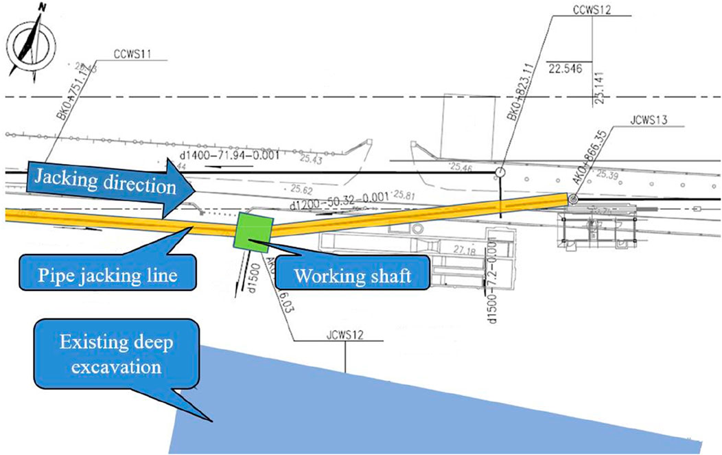
FIGURE 1. Plan of the pipe jacking line.
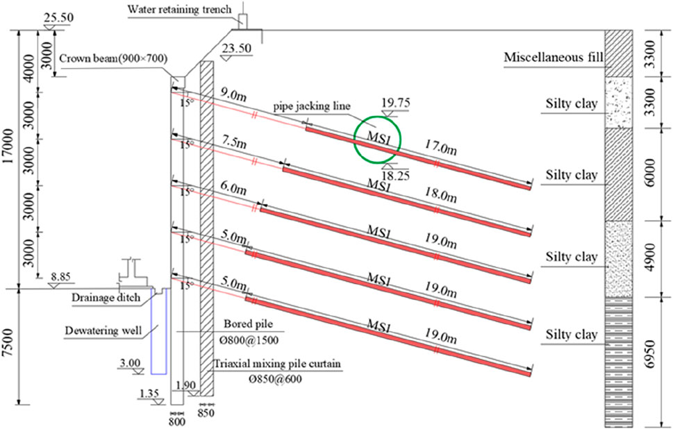
FIGURE 2. Profile of the retaining structure for the deep excavation of the sewage treatment plant.
The construction site is located in complex surroundings—adjacent to high-voltage lines, operating railway lines, and an existing sewage treatment plant (see Figure 3). As shown in Figure 3, working shaft JCWS1 was adjacent to the Shijiazhuang-Jinan high-speed railway line, which was in service at a distance of 40 m from the railway bridge pier. In addition, the working shafts JCWS1, JCWS2, and JCWS3 were next to 220-kV high-voltage transmission towers. Working shaft JCWS2 was approximately 15 m away from the high-voltage transmission towers.
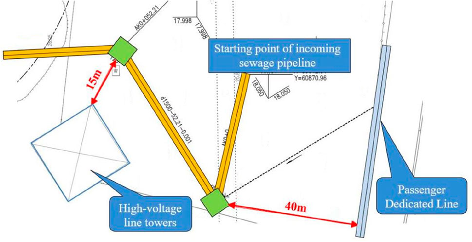
FIGURE 3. Location of the pipeline from the high-speed railway and transmission tower.
2.2 Geology and hydrology
The jacking pipe passed through a stratum composed of silty clay with a high silt content. The mechanical properties of in situ soils were obtained from laboratory experiments of the soil samples. The soil samples were obtained by a borehole at site. The mechanical properties of the soils are listed in Table 1. The ground at the site was a water-rich stratum with a high groundwater level. The groundwater level at the site was approximately 1.5 m. Thus, on this basis, engineering problems such as excavation surface failure and gushing water can easily occur.
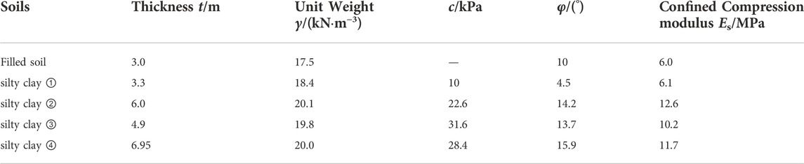
TABLE 1. Mechanical properties of soils.
3 Construction technologies for pipe-jacking crossing an existing anchor-cable group
3.1 Project difficulties
The primary construction challenges are based on the geological conditions, surrounding environment, and pipeline scenario of this project, which include
1) The area crossed by the existing anchor-cable group was large. The actual position of the anchor cables may deviate from the designed position owing to the construction deviation and geological conditions. Therefore, it is difficult to accurately identify the position of the anchor structure.
2) Anchor cables were densely distributed at the site. The normal pipe-jacking method for crossing this zone could would cause the anchor cables to be caught in the earth chamber of the pipe-jacking machine and wound screw conveyor, which would cause a failure of normal excavation and tunneling, and even damage the pipe-jacking machine.
3) The crossed soil layers are mostly composed of saturated silty clay with low mechanical properties, which belong to soft and water-rich strata. Therefore, excavation surface failure and gushing water can easily occur on this ground, which would present a high construction risk.
4) The working space at the construction site is restricted because it is adjacent to a deep excavation and a newly built structure at a distance of approximately 15 m. In addition, during the construction process, it is necessary to protect buildings and control their deformation.
3.2 Comparison of treatments for pipe jacking crossing an anchor-cable group
When the jacking pipe runs into an anchor group region, measures that deal with the anchor cable or improve the jacking devices need to be adopted to complete the construction of the subsequent sections. Currently, there are practical applications of pipe-jacking machines to cut through underground obstacles, such as isolated rocks and piles (Xu and Zuo, 2021). However, these pipe-jacking machines are under development and the technology is still in its infancy. Meanwhile, direct crossing large-scale anchor-cable structures has not yet been reported. Anchor tendons are often composed of strong and tough steel strands, which can easily wind around the cutter and damage the pipe-jacking machine. Based on the different anchor crossing and geological conditions, the anchor structures can be removed using different devices.
Based on this analysis, in this study, seven different treatments of pipe-jacking crossing anchor-cable group were compared and analyzed. The comparison and analysis results are listed in Table 2.
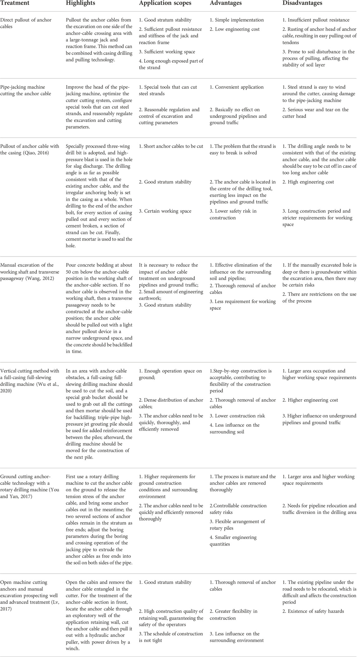
TABLE 2. Treatment comparison for the anchor-cable obstacle.
The advantages and disadvantages of various anchor-cable treatments are listed in Table 2. At the construction site in this study, the construction space is limited because the main structure located in the existing excavation has been constructed. Meanwhile, the friction and grip force of the anchor-cable structure are added because there are deviations in the anchor-cable drilling angles and serpentine drilling line. Therefore, it is not feasible to directly remove anchor cables and casing operations. The anchor-cable cutting method and rotary drilling machine method with full-casing and full-slewing drilling machines require complete removal of all anchor cables in the area of pipe jacking, which requires a great deal of engineering. In addition, the technology of direct cutting of anchor cables with a pipe-jacking machine and manual excavation of a transverse passageway is not yet mature. Therefore, the anchor-cable treatment of a steel-sheet pile and jet grouting pile for a waterproof and open-cut excavation method for crossing the anchor-cable area is proposed. The waterproofing is placed at the side wall of the excavation, with the joint efforts of a steel-sheet pile and high-pressure jet grouting piles at the rear. The anchor cables were removed using the open-cut excavation method. This scheme presents low risks and overcomes the problem of removing the anchor cables in the soft and water-rich stratum, and thus promotes the boring construction that assists in the jacking pipe’s rapid crossing of the anchor-cable section.
4 Treatment of the steel-sheet pile and jet grouting pile for the waterproof and open-cut method for crossing an anchor-cable area
4.1 Key construction technologies
In this case history, the treatment of 15 m-long Ⅳ Larsen steel-sheet pile, steel wales and jet grouting pile for a waterproof and open-cut excavation method for crossing the anchor-cable area was adopted. The profile of the steel-sheet pile is shown in Figure 4. The excavation depth of the excavation is approximately 8.5 m. Meanwhile, a 1.1-m working space is left on both sides of the jacking pipe at the bottom of the excavation. The steel wales were made of double-spliced 56C I-beams, which were set at 1 and 3.5 m below the top of the steel-sheet pile. Double-spliced 400 × 200 HN steel was installed between the steel wales as an internal support. Every 4 m of the steel strut support was welded to the steel wales and angle steel was welded at both ends of the support to prevent the support from falling off.
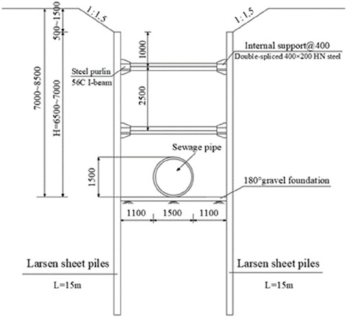
FIGURE 4. Profile of the steel-sheet pile support.
When the jacking pipe is about to be jacked into the anchor-cable area, Larsen sheet piles are applied within the construction control sideline but were placed away from any anchor cable (Figure 5). The ground is unloaded at the deeper excavation section within the range of 1.5 m on both sides of the steel-sheet pile, with a slope setting rate of 1:1.5.

FIGURE 5. Steel-sheet pile above the anchor cables cannot be overlapped. (A) Gap at pile head. (B) Gap between piles.
High-pressure jet grouting pile was set for waterproofing at the rear, without a steel-sheet pile (see Figure 6). The single pipe method was used for jet grouting and a jet grouting pile tightly coupled with the Larsen steel-sheet pile was adopted. The two drilling and intubation processes can be combined. Grouting is achieved with the help of jetting or vibration of the jet pipe. When the jet pipe sinks to the designed depth, the pressure of the high-pressure mud pump is increased to the designed construction value (20–40 MPa), which allows for 30 s of bottom-sitting and jetting. The drill bit is rotated while jetting and the drill pipe is lifted at the designed speed.
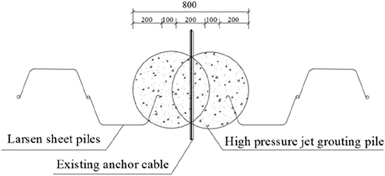
FIGURE 6. Overlapping of jet grouting piles and steel-sheet piles.
After the construction of the steel-sheet pile and jet grouting pile was completed, the anchor cable was cut with a toothless saw to release the tension stress of the anchor cable. The two severed sections of the anchor cables remained in the stratum as free ends. When the jacking pipe had crossed the anchor-cable area, the excavation was backfilled, the Larsen steel-sheet pile was pulled out in time for reuse, and sand was filled to reduce the ground settlement and displacement caused by excessive soil removal from the piles.
The construction method that is proposed in this case study to overcome the challenges from the pipe jacking crossing the anchor-cable group has significant advantages. First, the construction technologies used in this method are mature and reliable. Second, the cost of this method is acceptable, and is lower than those of the methods listed in Table 2. Third, waterproofing using a combination of Larsen steel-sheet piles and high-pressure jet grouting piles is effective and increases the stability of the excavation. Finally, high construction speed can shorten the construction period.
4.2 Study of the mechanical characteristics of a steel-sheet pile that is jacked into an existing anchor-cable area
It is important to measure whether the pile runs into the anchor-cable structure and learn about the mechanical characteristics of the steel-sheet pile during the construction process when applying a steel-sheet pile near an anchor-cable area. Therefore, we used a ZX-FBG-S01A surface fiber Bragg grating (FBG) sensor to monitor the mechanical response of the pile and actively take relevant effective measures for control or remedy to maximize the construction quality and safety of the soldier piles.
4.2.1 Basic principle of a surface FBG sensor and the layout of the measuring points
Surface FBG sensors were used to monitor the steel-sheet piles. Changes in the strain, stress, or other physical quantities measured around the grating cause a change in the grating period or refractive index of the fiber core, which leads to a wavelength shift of the grating FBG signal. The changes in the strain and stress of the steel-sheet pile can be obtained by measuring the wavelength shift, which can be derived from the following equation:
where λ is the measuring wavelength of the strain grating, in nm; λ0 is the initial wavelength of the strain grating, in nm; λt is the measuring wavelength of the temperature-compensated grating, in nm; λ’t is the initial wavelength of the temperature-compensated grating, in nm; a is the temperature sensitivity coefficient of the temperature-compensated grating, in nm/°C; b is the temperature coefficient of strain grating, in nm/°C; and K is the primary term coefficient of strain. This equation shows that the wavelength of the fiber grating is linearly related to the strain.
The layout of the fiber-optic grating sensors is shown in Figure 7. The sensors are placed vertically and welded in the middle of the grove side of the steel-sheet pile at approximately 0.5–1 m from the pile top. The two sensors were arranged symmetrically at a horizontal interval of 150 mm to obtain the measured wavelength of the strain grating of the steel-sheet pile under axial compression.
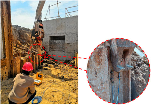
FIGURE 7. Position of the fiber grating sensor.
4.2.2 Analysis of the observation results
The measured wavelengths of the strain grating during the press-in and pullout of the steel-sheet pile were monitored throughout the process. The test signals were highly volatile because of the violent vibrations generated during the press-in and pullout of the steel-sheet pile. Therefore, FFT filtering is used to effectively filter the high-frequency signals and reduce the effect of vibration with a low-pass filter.
The mechanical characteristic curves of the measured and filtered values during the process of driving the steel-sheet pile into the anchor-cable area are shown in Figure 8. This figure also shows that before the steel-sheet pile was pressed in, there was no obvious deformation of the pile body and the wavelength fluctuated regularly. This indicates the high sensitivity of the FBG sensor. When the steel-sheet pile is pressed into the soil normally, the stress on the pile cap is roughly linearly related to the press-in depth. The soil layer is relatively uniform, and the maximum stress and strain are 31.2 MPa and 151.4 με, respectively. Subsequently, the steel-sheet pile was slowly pulled out. With the second press-in of the pile, the stress and deformation of the pile cap increased to the peak of the first press-in. When the steel-sheet pile touched the anchor cable during the press-in process, the compressive stress in the steel-sheet pile cap increased rapidly until it reached 62.8 MPa, which is the maximum pressure of the pile-pressing machine. The corresponding final strain of the pile body was 304.8 με, which is two times more than when the anchor cable was not touched.
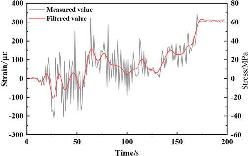
FIGURE 8. Comparison curve of mechanical characteristics of steel-sheet pile pressed into anchor-cable area.
5 Field measurement and numerical investigation
5.1 Field measurement analysis
The excavation followed an east–west direction. To further analyze the supporting effect of the steel-sheet pile and the settlement behind the pile during the excavation of the existing anchor-cable area, inclinometers behind the piles and settlement measuring points were laid during the construction (see Figure 9). Settlement measuring points were laid behind the position where the inclinometers were embedded. Seven surface settlement measuring points were laid in each group, perpendicular to the direction of the side wall of the excavation, at distances of 3, 5, 8, 11, 15, 20, and 25 m from the excavation.
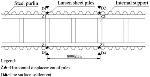
FIGURE 9. Layout of monitoring points.
5.1.1 Deformation variation of the sheet pile
The soil on the south side is the area crossing the anchor-cable group, which is reinforced by the anchor-cable structure. Thus, the pile on this side exhibited a small horizontal deformation. Therefore, this study mainly focused on the horizontal displacement of the pile on the north side of the excavation. Figure 10 shows the horizontal displacement curves of the piles at monitoring points Z1 and Z2 at various excavation depths. Figure 10 shows that the deformation at the top and bottom of the steel-sheet pile was relatively small because it was affected by the internal support constraints. The middle part of the pile protrudes into the excavation, showing a typical “fish-belly” deformation pattern. With an increase of the excavation depth, the horizontal displacement of the pile top did not change significantly. The maximum horizontal displacement of the steel-sheet pile was located at the bottom of the excavation, where He = 6.5 m (He represents the excavation depth). The maximum horizontal displacements of the piles at Z1 and Z2 are 6.01 and 5.83 mm, respectively, which are approximately 0.092% and 0.089% of the excavation depth He. The overall deformation was much smaller than the monitoring warning value (National Bureau of Standards of China (NBS), 2019). The anchor-cable area is supported by steel wales and internal support, combined with reinforcement with jet grouting pile waterproof at the rear of the steel-sheet pile. This can effectively suppress the deformation of the retaining structure.
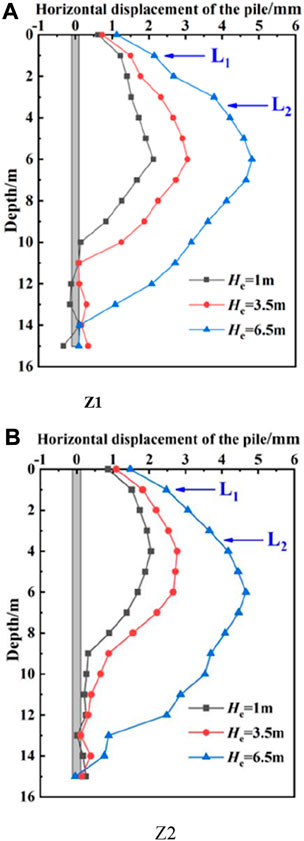
FIGURE 10. Horizontal displacement curve of retaining pile. (A) Z1. (B) Z2.
The relationships between the maximum horizontal displacement δv and excavation depth He of the excavation with and without anchor cables were analyzed. According to the results from a previous study (Han et al., 2017), δv increases approximately linearly with He. In this study, the measured data of excavation were collected for comparison, and the soldier piles were divided into a strut system and a tieback system based on the support type (see Figure 11). As shown in Figure 11, the statistics from the literature (Masuda, 1993; Ou et al., 1993) show a significant dispersion and a large deformation range of the retaining structure: δv is 0.03%–0.58% He and 0.14%–0.60% He, respectively, with a mean value of 0.28% He. The excavations at both sites were alternating strata of sand and clay. The design and construction technology of the support structure are relatively backward, which results in large deformation of the retaining structure. According to the statistics in the literature (Khoiri and Ou, 2013), the two square deep excavations retained by underground diaphragm walls and constructed with the top-down method were located in sandy soil stratum, with δv varying from 0.14%–0.33% He and with a mean value of 0.23%He.
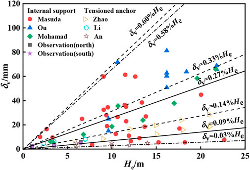
FIGURE 11. Relationship between maximum horizontal displacement of retaining structures and excavation depth.
According to the statistics in the literature (An and Gao, 2007; Li et al., 2008; Zhao et al., 2015), the variation range of the excavation data using pile-anchor support is reduced, with the δv between 0.03% and 0.14% He, indicating that the tieback system can provide superior control of the deformation of the retaining structure of the excavation. Among them, the soil layer where the excavation is located (An and Gao, 2007) has geological conditions similar to those of this project. It is primarily mucky and silty clay, which is soft. Therefore, the cable-anchored piles are adopted in the soft soil excavation, which effectively controls the deformation of the support structure and soil.
The average values of maximum lateral displacement under the support of the strut system and tieback system are 0.26% He and 0.11% He, respectively. This indicates that the tieback system can provide superior control of the deformation of the retaining structure of excavation with the improvement of construction technology. In this study, the maximum horizontal displacement δv of the soldier pile on the north side of the excavation was 0.09%–0.27% He, with a mean value of 0.15% He. Compared to the ordinary internal support system, the support method of the steel strut system combined with the jet grouting pile at the rear can better control the deformation of the retaining structure of excavation. There is an existing anchor structure on the south side of the excavation and the maximum lateral displacement of the soldier pile δv is 0.12% He, on average. This indicates that the existing anchor cable can reinforce the soil layer crossing the excavation to a certain extent. Therefore, the support scheme of the Larsen steel-sheet pile, steel wale support, and jet grouting pile waterproofing is better for controlling the deformation.
5.1.2 Ground surface settlement behind the piles
To analyze the surface settlement outside the excavation, representative measuring points on the north side of the excavation were chosen (see Figure 12). This figure shows that the surface settlement curve is in the “groove type.”. The settlement value first increases and subsequently decreases with the increase of distance, and the maximum surface settlement is observed at 8 m from the edge of the excavation. The settlement in the surrounding area increased with the excavation depth. The maximum settlement δh is 19.1 mm, which is approximately 0.29% of the excavation depth He. The settlement at 25 m from the edge of the excavation is 3.5 mm, which gradually tends to 0.
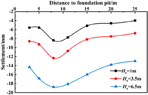
FIGURE 12. Ground surface settlement curve behind pile.
5.2 Numerical model
5.2.1 Numerical model establishment
To further analyze the overall safety of the support structure, the finite element numerical simulation method is used to investigate the mechanical effect of a retaining structure on the excavation and the stratum deformation variation in an area where the anchor cables cross. The influence of the anchor cables of the excavation support of the existing sewage treatment plant on the stability of the excavation was investigated. Considering the model’s accuracy, the influence of excavation on horizontal and vertical directions is generally around 3–5 times that of He (Wang et al., 2022). According to the dimensions of the existing excavation and the crossing excavation in the project, in this model the influence range of the excavation crossing the excavation on the depth and width around is considered to be 3.5 times of excavation depth. In addition, considering the calculation scale, half the size of the existing excavation was considered for modeling. Because the excavation across the anchor-cable area was longer in the longitudinal direction, the excavation angle effect was not significant. Therefore, the longitudinal extension size of the model was reduced and the final geometric dimension of the model was set to 79 m × 39 m × 24 m, using 61,150 elements; as shown in Figure 13. The normal movement was restrained for the lateral boundaries. All movements were restrained at the bottom boundary. All movements were allowed at the top of the boundary.
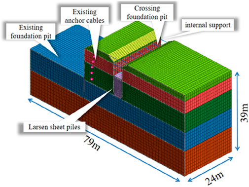
FIGURE 13. Profile of the numerical model.
The soil layer at the site is primarily silty clay. Given that the soil layer in the site is uniformly distributed, it is simplified for analysis. The Hardening-Soil (HS) model was used as the soil constitutive model. Taking the Mohr–Coulomb as the failure criterion, this model can consider both shear hardening and compression hardening, and can accurately reflect the nonlinear mechanical characteristics during soil loading and unloading (Zhao et al., 2018). The HS model implements 11 parameters (e.g., strength parameters, stiffness parameters, and advanced parameters), which were obtained from the triaxial and consolidation tests. The stiffness parameters in the HS model consist of three stress-dependent stiffness parameters, Eref50, Eref oed, and
The construction processes in the model primarily includes construction of existing excavation and stratified construction of the crossing excavation. There were 21 construction steps involved in the numerical investigation. The construction of existing excavation consists of unloading and slope setting, construction of cast-in situ bored piles, stratified precipitation of excavation, main soil excavation, and side wall anchor-cable support. Displacement clearing was carried out, and then construction of the crossing excavation was carried out, which mainly included the Larsen sheet pile support, steel strut installation, and anchor-cable removal in the excavation region.
The mechanical parameters of retaining structures in the numerical model are listed in Table 3. For the pile wall, the lateral force is the main load acting on the pile wall. The nonvolume, linear elastic plate elements, which can provide bending resistance, were used to simulate the behavior of the pile wall. The mechanical parameters of the piles were replaced by those of a diaphragm wall according to the equivalent of lateral stiffness. The equivalent wall had a thickness of 0.112 m. Soil–wall interaction was simulated with a zero-thickness interface element. The interfacial strength reduction factor Rinter was set as 0.6 (Khoiri and Ou, 2013). The separation and slip characteristics of soil–wall interaction were taken into account. The existing excavation was supported by a cap beam and anchor cable. The piles were anchored using five rows of prestressed anchor cables. The anchor cable was simulated with an implanted truss unit with a vertical spacing of 3 m and a horizontal spacing of 2 m. Prestress was applied to the anchor cables. The prestress designed value was 200 kN. The steel wales, cap beams, and steel struts were simulated with beam elements.
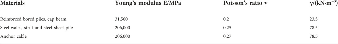
TABLE 3. Mechanical parameters of retaining structures in the numerical model.
To further analyze the influence of the anchor cable of the existing excavation on the stability of the crossed excavation, the mechanical effect of the retaining structure and the stratum deformation variation with and without anchor cables were studied. The cases of the ground with and without existing anchor cables were named Case 1 and Case 2. To ensure that the pile displacement of the existing excavation in Case 2 is the same as that in Case 1, this study used the displacement control method (DCM) to apply displacement to the existing excavation sidewalls to simulate the effect of previous excavation under the corresponding working conditions (Cheng et al., 2007). In the numerical investigation, the deformation of the piles of the existing excavation in Case 1 at each calculation step was recorded. When Case 2 was calculated, the nodes of piles of the existing excavation were controlled using displacement boundary according to the results recorded in Case 2. Based on this setting, the mechanical effect of anchor cables could be analyzed according to a comparison between Case 1 and Case 2.
5.2.2 Numerical model validation
To verify the accuracy of the finite element model and the selected parameters, the calculated values of Case 1 and measured values of pile horizontal displacement and surface settlement when the excavation is excavated to the bottom of the excavation (He = 6.5 m) are shown in Figures 14, 15, respectively. Due to the limitation of the clinometer, the measured deformation at the bottom of the soldier pile was 0. To facilitate the comparison between the numerical calculated results and measured data, the horizontal displacement curve of the pile from the numerical simulation was panned to the point where the horizontal displacement of the pile bottom was 0. Figure 14 shows that the change trend of the finite element simulation results and the measured results are basically consistent, especially at the peak of deformation at the pit bottom. There is a certain deviation between the measured and calculated values of horizontal displacement of the piles because the inclinometers were installed in the ground behind the steel-sheet piles. Figure 15 shows that the calculated value of surface settlement is soundly consistent with the measured results on site, and the surface settlement is in a “groove type.” The actual settlement value near the edge of the excavation was slightly larger than the calculated value, which was primarily due to the soil loss between piles during construction. By comparison, the calculated results are basically consistent with the measured data. This indicates that the accuracy of the model can meet the requirements of the research analysis.
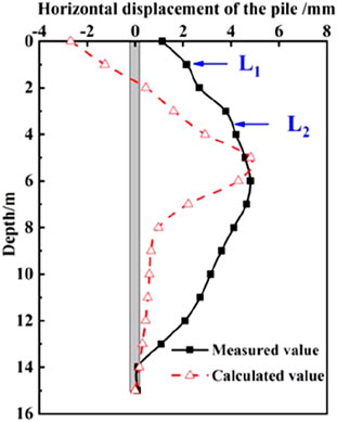
FIGURE 14. Horizontal displacement comparison curve of retaining pile.
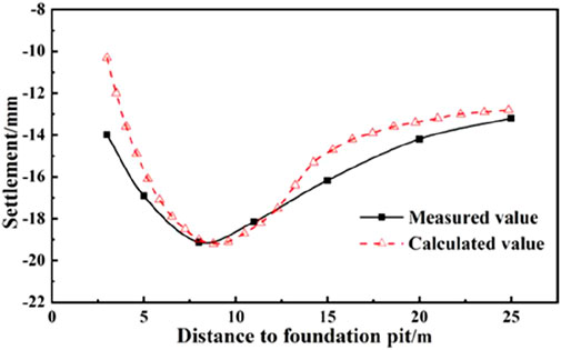
FIGURE 15. Comparison curve of surface settlement behind pile.
5.3 Numerical result analysis
5.3.1 Analysis of the mechanical effect of the retaining structure crossing the excavation
The horizontal displacement of the piles of Case 1 and Case 2 on both sides of the excavation is compared in Figures 16, 17, where L1 and L2 represent the positions of the internal supports. This figure shows that with the anchor-cable retaining, the peak horizontal displacement of the pile gradually increases with the excavation and its location moves down with the excavation. The maximum displacement in each stage occurs near the excavation bottom. The steel-sheet pile on the left-hand side of the excavation (e.g., the side adjacent to the existing excavation) shows an obvious displacement turning point at the application of internal support. Meanwhile, the horizontal displacement of the steel-sheet pile on the right-hand side (e.g., the side far from the existing excavation) is primarily affected by the lateral earth pressure behind the pile due to the large amount of soil behind the pile and also because the influence of internal support under the earth pressure is smaller.

FIGURE 16. Comparison of horizontal displacement of the retaining pile on the right-hand side of the excavation. (A) He=1 m. (B) He=3.5 m. (C) He=6.5 m.
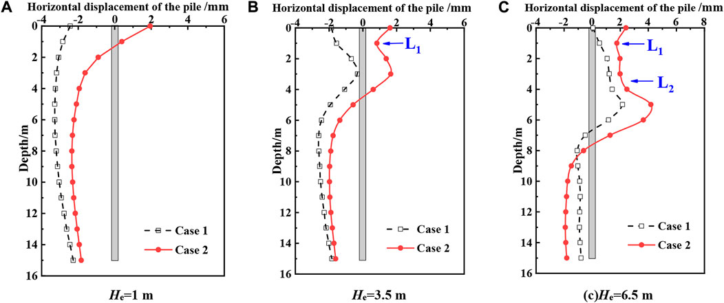
FIGURE 17. Comparison of horizontal displacement of retaining pile on the left side of excavation. (A) He=1 m. (B) He=3.5 m. (C) He=6.5 m.
Figures 16A, 17A show that without the anchor-cable support, the horizontal displacement curve of the soldier pile deviates greatly from the pile top toward the excavation at the early stage of excavation. This presents a typical deformation pattern of cantilever support structure, especially for the right-hand steel-sheet pile, of which the horizontal displacement changes completely opposite to that when with the anchor cable. This indicates that the anchor-cable group in the soil can obviously correct the tilt of the soldier pile. The deformation of the top of the soldier pile of Case 2 gradually decreases after the excavation, and following the application of wales and internal support. The trend of the horizontal displacement of the pile of Case 1 is basically the same as that of Case 2 from a position of 3 m from the pile top. The maximum horizontal displacement of the pile δv of Case 2 is 9.2 mm, which is approximately 0.014% of the excavation depth He, and is 41.5% greater than that of Case 1.
5.3.2 Analysis of stratum deformation variation
In addition to the horizontal displacement of the soldier pile, the environmental effect caused by the removal of the existing anchor cable using the open-cut excavation method is also crucial. Figures 18, 19 show the comparison curves of the ground settlement of both sides of the crossing excavation, the upper surface of the anchor-cable area, and the soil at 3 m underground of two Cases, respectively. Figure 18 shows that the settlement trend around the excavation of Case 1 is basically the same as that of Case 2, both presenting a groove shape. The major influence range of the settlement of Case 2 is twice the excavation depth, which meets the requirement of the horizontal range of the influence area (Hsieh and Ou, 1998). The influence range of the settlement of Case 1 is slightly larger as the integrity of the soil behind the excavation improves (Han and Lee, 2020). The settlement peaks δh at the surface and 3 m below the ground in the natural soil layer of Case 1 are 19.2 and 17 mm, respectively, both at 9 m from the excavation. When there are no anchor cables, the settlement peaks δh lag slightly, and are 17.8 and 15 mm, respectively, at 10 m from the excavation, which are 1.4 and 2 mm lower than those with anchor cables.
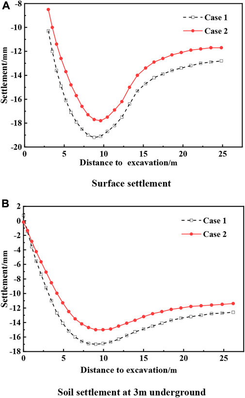
FIGURE 18. Settlement curves at the right side of Case 1 and Case 2. (A) Surface settlement. (B) Soil settlement at 3 m underground.
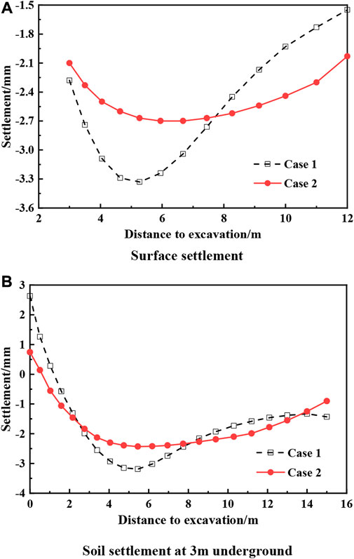
FIGURE 19. Settlement curves at the left-hand side of Case 1 and Case 2. (A) Surface settlement. (B) Soil settlement at 3 m underground.
Figure 19 shows that the settlement curve pattern at the left-hand side basically matches that at the right-hand side of the excavation and is consistent with the settlement change pattern of the support structure of a piled anchor. Figure 19A shows that with sufficient support, the surface settlement on the side near the existing excavation side is only 1.6 mm, whereas the surface settlement on the side of crossing excavation increases due to the weakness of the anchor cable. Because of the support of the existing anchor cable and the soldier piles on both sides, the peak of surface settlement is controlled at 3.3 mm, which is much smaller than the 19.2 mm on the right-hand side of the soldier piles.
5.3.3 Excavation stability analysis
The stability of an excavation or slope is important for a project’s safety (He and Kusiak, 2017; Li et al., 2021b; Li et al., 2021c; Cui et al., 2021; Zhou et al., 2021; Li et al., 2022). The methods of excavation stability analysis include the limit equilibrium method, limit analysis method and strength reduction method. The strength reduction method is used often in finite element analysis to calculate the stability of the excavation. Specifically, the strength parameters c and φ are reduced through small increments until the limit state of the soil is reached. The minimum safety factor and failure mode (Han et al., 2022) of the excavation construction are then determined according to various shapes, loads, and boundary conditions. The stability safety factor Fs of the excavation is determined using the following equation:
where c0 and φ0 are the initial strength parameters when defining the soil properties, and cr and φr are the reduced soil strength parameters. The strength reduction method was used to calculate the overall instability state of the excavation, and the reduction ratio was the stability safety factor of the excavation. The safety factors of excavation stability of Case 1 and Case 2 were calculated to be 2.3 and 1.5, respectively, which are high and this indicates that an excavation collapse will not easily occur.
Figure 20 shows the equivalent strain of the soil, which reflects the damage contour of the excavation surface when the soil reaches the limit state in the process of strength reduction. Figure 20A shows that the maximum plastic strain occurred on both sides of the excavation bottom and the plastic strain area extended in all directions at an angle of approximately 45°. Under the constraint of the anchor cable, the plastic strain area of the soil layer is smaller on the left-hand side of the crossing excavation and the deformation of the excavation bottom is well controlled. When compared with Figure 20B, it can be seen that without anchor cables, the plastic strain area is larger, extending from the bottom of the crossing excavation to the sidewall of the existing excavation, and the largest deformation occurs at the bottom of the crossing excavation. The bottom of the excavation swells. This indicates that the anchor cables in the sidewall of the existing excavation can effectively suppress the equivalent strain of soil during the excavation of the crossing excavation.
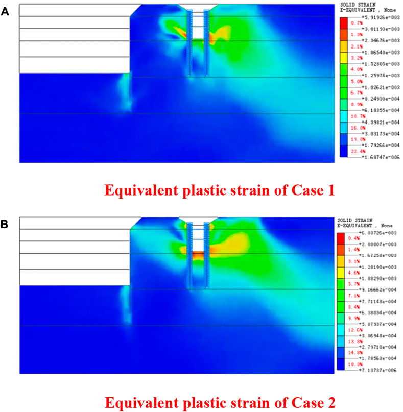
FIGURE 20. Comparison of equivalent plastic strain of the excavation. (A) Equivalent plastic strain of Case 1. (B) Equivalent plastic strain of Case 2.
6 Conclusion
Based on the construction project of the inlet and outlet pipe network of Jinan East Railway Station Area Sewage Treatment Plant, the following conclusions were drawn through the compilation and analysis of the on-site measured data during the excavation of the anchor-cable area. The conclusions were also based on the analysis of the mechanical effects of the retaining structure and stratum deformation variation with and without anchor cables using finite element simulation. The construction method presented in this case study guarantees the safe construction of the pipeline. This is a beneficial attempt for the pipe jacking crossing through obstacles and is an important guideline for other obstacle crossing project.
1) A construction scheme of the steel-sheet pile and jet grouting pile for waterproof and open-cut excavation for crossing the anchor-cable area is proposed for the engineering problem of pipe jacking crossing the dense anchor-cable section in soft and water-rich strata. When the steel-sheet pile is pressed in and touches the anchor cable, the compressive stress at the pile top rapidly increases to twice the stress in the case of the normal press-in. The maximum lateral displacements of the retaining structure on both sides of the excavation δv are 0.15% He and 0.12% He, respectively. This indicates a strong ability to control deformation.
2) The surface settlements on both sides of the crossing excavation are in “groove type,” increasing first and then decreasing with the increase of distance, which is consistent with the settlement change pattern of the support structure of the piled anchor. The maximum soil settlement δh is 0.29% He and 0.05% He, respectively. This indicates that the anchor cables of the existing excavation can effectively control the settlement of soil outside the excavation.
3) Without an anchor-cable support at the existing excavation sidewalls, the top of the soldier pile of crossing excavation presents a typical deformation pattern of the cantilever support structure. The maximum displacement at all stages occurs near the excavation bottom. The maximum horizontal displacement of the pile is 9.2 mm, which is 41.5% higher than that observed with the anchor cable. This indicates that the anchor-cable group in the soil can effectively control the deformation of the retaining structure.
4) The maximum plastic strain during the excavation construction occurs on both sides of the excavation bottom and the plastic strain area extends in all directions at an angle of approximately 45°. With anchor cables, the plastic strain area on both sides of the excavation is smaller and the deformation of the excavation bottom is well controlled; without anchor cables, the plastic strain area on both sides of the excavation is larger, which leads to an obvious decline in the stability of the excavation. The anchor cables in the sidewalls of the existing excavation can effectively suppress the equivalent strain of soil during the excavation of the crossing excavation.
Data availability statement
The original contributions presented in the study are included in the article/supplementary material; further inquiries can be directed to the corresponding authors.
Author contributions
JH: conceptualization, methodology, software, and writing—original draft. JW: writing—review and editing and data curation. DJ: investigation, writing—review and editing, and resource. FY and DL: data curation. YZ: language editing and investigation. XB: writing—review and editing. NY: formal analysis. GY: investigation.
Funding
This work was supported by the National Natural Science Foundation of China (Grant No. 42172310) and the Doctoral Research Fund of Shandong Jianzhu University (Grant No. X19080Z).
Acknowledgments
We deeply appreciate the warm and efficient work of the editors and reviewers.
Conflict of interest
Authors DJ and FY were employed by the company The Third Construction Co., Ltd. of CTCE Group. Author GY was employed by the company Shandong Hi-Speed Construction Management Group Co. Ltd.
The remaining authors declare that the research was conducted in the absence of any commercial or financial relationships that could be construed as a potential conflict of interest.
Publisher’s note
All claims expressed in this article are solely those of the authors and do not necessarily represent those of their affiliated organizations, or those of the publisher, the editors, and the reviewers. Any product that may be evaluated in this article, or claim that may be made by its manufacturer, is not guaranteed or endorsed by the publisher.
References
An, G., and Gao, J. (2007). Comprehensive analysis of deep foundation pits for underground space in Guangzhou. Chin. J. Geotechnical Eng. 29 (6), 872–879.
Brinkgreve, R. B. J., Swolfs, W. M., and Engin, E. (2010). PLAXIS version 8 material models manual. The Netherlands.
Cheng, C. Y., Dasari, G., Chow, Y., and Leung, C. (2007). Finite element analysis of tunnel–soil–pile interaction using displacement controlled model. Tunn. Undergr. Space Technol. 22 (4), 450–466. doi:10.1016/j.tust.2006.08.002
Cheng, M., and Lu, Y. (2015). Developing a risk assessment method for complex pipe jacking construction projects. Automation Constr. 58, 48–59. doi:10.1016/j.autcon.2015.07.011
Cui, S., Pei, X., Jiang, Y., Wang, G., Fan, X., Yang, Q., et al. (2021). Liquefaction within a bedding fault: Understanding the initiation and movement of the Daguangbao landslide triggered by the 2008 Wenchuan Earthquake (Ms = 8.0). Eng. Geol. 295 (20), 106455. doi:10.1016/j.enggeo.2021.106455
Fu, Y., Zhang, C., Yin, J., Gu, R., and Zhang, A. (2018). Scheme design for removing cables of existing foundation pit intruding into metro station foundation pit. Tunn. Constr. 38 (10), 1706–1711.
Han, J., and Lee, H. (2020). The effects of hardcore smokers' depression and self-esteem on daily smoking amount. Arch. Psychiatr. Nurs. 52 (4), 149–158. doi:10.1016/j.apnu.2020.02.006
Han, J., Liu, D., Guan, Y., Chen, Y., Li, T., Jia, D., et al. (2022). Study on shear behavior and damage constitutive model of tendon-grout interface. Constr. Build. Mater. 320, 126223. doi:10.1016/j.conbuildmat.2021.126223
Han, J., Zhao, W., Chen, Y., Jia, P. J., and Guan, Y. P. (2017). Design analysis and observed performance of a tieback anchored pile wall in sand. Math. Problems Eng. 2017, 1–23. doi:10.1155/2017/8524078
Han, W., Cao, J., Pang, L., Han, Z., and Lui, B. (2019). Construction technology of slurry balance shield passing anchor cable area. Constr. Technol. 48 (7), 75–79.
He, Y., and Kusiak, A. (2017). Performance assessment of wind turbines: Data-derived quantitative metrics. IEEE Trans. Sustain. Energy 9 (1), 65–73. doi:10.1109/tste.2017.2715061
Hsieh, P., and Ou, C. (1998). Shape of ground surface settlement profiles caused by excavation. Can. Geotech. J. 35 (6), 1004–1017. doi:10.1139/t98-056
Ji, X., Ni, P., Barla, M., Zhao, W., and Mei, G. (2018). Earth pressure on shield excavation face for pipe jacking considering arching effect. Tunn. Undergr. Space Technol. 72, 17–27. doi:10.1016/j.tust.2017.11.010
Ji, X., Zhao, W., Ni, P., Barla, M., Han, J., Jia, P., et al. (2019). A method to estimate the jacking force for pipe jacking in sandy soils. Tunn. Undergr. Space Technol. 90, 119–130. doi:10.1016/j.tust.2019.04.002
Khoiri, M., and Ou, C. (2013). Evaluation of deformation parameter for deep excavation in sand through case histories. Comput. Geotechnics 47, 57–67. doi:10.1016/j.compgeo.2012.06.009
Khoiri, M., Ou, C., and Teng, F. (2014). A comprehensive evaluation of strength and modulus parameters of a gravelly cobble deposit for deep excavation analysis. Eng. Geol. 174, 61–72. doi:10.1016/j.enggeo.2014.03.008
Li, G. (2014). Anchoring cable removing technology: Case study on hui-min shield-bored tunnel on line 1 of Zhengzhou metro. Tunn. Constr. 34 (5), 494–498.
Li, H., Deng, J., Feng, P., Pu, C., Arachchige, D. D. K., and Cheng, Q. (2021). Short-term nacelle orientation forecasting using bilinear transformation and ICEEMDAN framework. Front. Energy Res. 9, 780928. doi:10.3389/fenrg.2021.780928
Li, H., Deng, J., Yuan, S., Feng, P., and Arachchige, D. D. K. (2021). Monitoring and identifying wind turbine generator bearing faults using deep belief network and EWMA control charts. Front. Energy Res. 9, 799039. doi:10.3389/fenrg.2021.799039
Li, H., He, Y., Xu, Q., Deng, J., Li, W., and Wei, Y. (2022). Detection and segmentation of loess landslides via satellite images: A two-phase framework. Landslides 19 (3), 673–686. doi:10.1007/s10346-021-01789-0
Li, J., Yue, Y., Mao, Q., and Zhang, Z. (2008). Design of anchor piles brace structures for soft soil foundation pits. Rock Soil Mech. 29 (9), 2551–2555.
Li, T., Zhao, W., Liu, R., Han, J., and Cheng, C. (2021). Experimental study on the pipe-soil interface under the influence of pipe jacking stagnation time. KSCE J. Civ. Eng. 26, 1428–1438. doi:10.1007/s12205-021-0642-4
Lv, J. (2017). Countermeasures for shield crossing anchor cable group during construction of cable tunnel in North Ring of Shenzhen. Tunn. Constr. 37 (S1), 155–162.
Masuda, T. (1993). Behavior of deep excavation with diaphragm wall. Cambridge: Massachusetts Institute of Technology.
National Bureau of Standards of China (NBS) (2003). Steel strand for prestressed concrete (GB/T 5224-2003). Beijing, China: NBS.
National Bureau of Standards of China (NBS) (2019). Technical standard for monitoring of building excavation engineering (GB 50497-2019). Beijing, China: NBS.
Ou, C., Hsieh, P., and Chiou, D. (1993). Characteristics of ground surface settlement during excavation. Can. Geotech. J. 30 (5), 758–767. doi:10.1139/t93-068
Qiao, H. (2016). Comparison and selection of the treatment plan for the shield encountering anchor cable during construction. Railw. Constr. Technol. 4, 44–48.
Wang, F., Yuan, D., Dong, Z., Han, B., Nan, H., and Wang, M. (2013). Study on cutter configuration for directly shield cutting of large-diameter piles. China Civ. Eng. J. 46 (12), 127–135.
Wang, F., Yuan, D., Dong, Z., Han, B., Nan, H., and Wang, M. (2013). Test study of shield cutting large-diameter reinforced concrete piles directly. Chin. J. Rock Mech. Eng. 32 (12), 2566–2574.
Wang, J., Han, J., Chen, J., and Ding, G. (2022). Experimental and numerical study on the dynamic response of a superthick backfill subgrade under high-speed railway loading: A case study of qianjiang-zhangjiajie-changde railway. J. Constr. Eng. Manag.
Wang, M. (2012). Comparative study on schemes of shield tunneling under high-riser basement. Urban Mass Transit 15 (6), 104–108.
Wu, J., He, H., Zhao, D., Zhao, Y., and Fan, W. (2020). Combined application of the full-sleeve full-rotating drill rig and rotary drilling rig in ultra-thick backfill complex formation. Constr. Technol. 49 (1), 16–18.
Xu, P., and Zuo, S. (2021). Study on the JH-2 model parameters for metro shield cutting reinforced concrete pile. Geotech. Geol. Eng. (Dordr). 39, 5267–5278. doi:10.1007/s10706-021-01830-y
Xu, T., Wang, L., Zhang, P., Zhou, Y., Liu, K., Feng, X., et al. (2022). Key techniques for rapid jacking and laying of pipelines: A case study on ‘jingshihan’ gas pipelines in China. Energies 15, 2918. doi:10.3390/en15082918
Yan, Y., and Chen, Y. (2011). 3D numerical simulation of metal cutting processes using a thermomechanical coupled approach. J. Mech. Strength 33, 845–849.
Ye, J. (2017). Study on comprehensive removal technology of existing anchor rope for shield tunneling. J. Munic. Technol. 35 (3), 68–71.
You, J., and Yan, Y. (2017). Construction techniques for a shield running tunnel passing through the anchor cables of an adjacent foundation pit in soft strata. Mordern Tunn. Technol. 54 (5), 229–235.
Yuan, H., Wang, B., Zhu, D., Chen, S., Han, Z., and Yao, H. (2014). Mechanical behaviours of a shield tunnel adjacent to existing viaduct pile foundations. Chin. J. Rock Mech. Eng. 7, 1457–1464.
Zhao, W., Han, J., Li, S., and Guan, Y. (2015). Stresses and deformations in pile-anchor support system of deep foundation pit in sandy layers. Jouranl Northeast. Univ. Nat. Sci. 36 (4), 576–580.
Zhao, W., Han, J. Y., Chen, Y., Jia, P. J., Li, S. G., Li, Y., et al. (2018). A numerical study on the influence of anchorage failure for a deep excavation retained by anchored pile walls. Adv. Mech. Eng. 10 (2), 168781401875677. doi:10.1177/1687814018756775
Keywords: pipe jacking, crossing obstacles, anchor cables, deep excavation, numerical simulation
Citation: Han J, Wang J, Jia D, Yan F, Zhao Y, Bai X, Yan N, Yang G and Liu D (2023) Construction technologies and mechanical effects of the pipe-jacking crossing anchor-cable group in soft stratum. Front. Earth Sci. 10:1019801. doi: 10.3389/feart.2022.1019801
Received: 15 August 2022; Accepted: 27 September 2022;
Published: 10 January 2023.
Edited by:
Jingren Zhou, Sichuan University, ChinaCopyright © 2023 Han, Wang, Jia, Yan, Zhao, Bai, Yan, Yang and Liu. This is an open-access article distributed under the terms of the Creative Commons Attribution License (CC BY). The use, distribution or reproduction in other forums is permitted, provided the original author(s) and the copyright owner(s) are credited and that the original publication in this journal is cited, in accordance with accepted academic practice. No use, distribution or reproduction is permitted which does not comply with these terms.
*Correspondence: Jun Wang, d2FuZ2p1bkBzZGp6dS5lZHUuY24=; Yue Zhao, emhhb3lAc2Rhcy5vcmc=