
94% of researchers rate our articles as excellent or good
Learn more about the work of our research integrity team to safeguard the quality of each article we publish.
Find out more
ORIGINAL RESEARCH article
Front. Earth Sci., 30 September 2022
Sec. Solid Earth Geophysics
Volume 10 - 2022 | https://doi.org/10.3389/feart.2022.1008757
This article is part of the Research TopicUnconventional Hydrocarbon Resources Evaluation Through Geological, Geophysical and AIView all 9 articles
 Ibrar Iqbal1
 Bin Xiong1*
 Gang Tian2†
 Amjad Ali2†
 Sanxi Peng1
 Gao Wen1
 Xingfu Huang1
 Aqsa Anees3
 Umar Ashraf3*
 Amr Abd El-Raouf4
Ground-penetrating radar (GPR) is one of the most important techniques for obtaining high-resolution data in archaeological research, and it is becoming increasingly important. The continuous wavelet transform (CWT), which is non-numerical technique, gives an overcomplete representation of a signal by continuously varying the wavelet’s translation and scale parameters in the time series dataset. This paper focuses on the novel technique of integrating CWT and the wavelet transform maxima (WTM) to extract information from an archaeological test site in south-eastern China. For the characterization of archaeological features, we assessed the importance of dense and accurate data collection as well as GPR signal processing. The mathematical formulation and applicability of GPR attributes, particularly amplitude-based attributes, to identify and characterize archaeological buried targets are also discussed. GPR data is acquired using co-polarized and cross-polarized configurations with transverse-electric (TE) and transverse-magnetic (TM) broadside frequency plates at 100 and 200 MHz. Next, CWT was applied using six different wavelet levels, followed by amplitude comparison. The archaeological targets were successfully interpreted using peak amplitude and CWT. The proposed methodology has significantly improved data visualization and interpretation of GPR data, and it also gave us good results in identifying archaeological anomalies.
GPR is a non-destructive geophysical method that images the subsurface using radar pulses (Economou et al., 2015; Iqbal et al., 2020). GPR is notable for its notoriously difficult automated data analysis, although it is particularly promising for soil studies. The GPR method, which is based on wave propagation and operates in the frequency range of 10–6 GHz, is well known for its high resolution and is widely used for near-surface exploration. The basic themes in archaeology are attributes such as size, shape, depth, and, most importantly, the location of cultural remains and related stratigraphy. To accomplish this, the majority of the time critical reflections are identified and correlated with 2D profiles (Davis and Annan, 1989), (Zhao et al., 2013; Iqbal et al., 2018). Because of the wide spread of cultural material, archaeologists must explore and describe earthen archaeological properties in near-surface geophysical exploration. Earthen archaeological features include wedged platforms, Earth ovens, antique Earth walls, kiln sites, storage pits, and one around, most of which are found in prehistoric colonies. It is difficult to define rammed Earth archaeological traits from geophysical exploration and development due to minimal target/background contrast (Forte and Pipan, 2008; Zhao et al., 2015). Under ideal circumstances, GPR can quickly and efficiently provide detailed information about buried objects (Kumar et al., 2020). 3-D multichannel GPR arrays have also recently been introduced, allowing for the development of more advanced acquisition and processing techniques and higher resolution (Trinks et al., 2010; Lualdi and Lombardi, 2014). However, common offset (CO) measurements are still the most popular data acquisition method because they are faster to perform and process (Iqbal et al., 2021). In addition to identifying entombed remains (which would otherwise create significant research), GPR and electrical resistivity tomography (ERT) methods can help the archaeological research by mapping large areas and creating a more comprehensive view of eutrophication in the subsurface to allow researchers quickly identify settlement dynamic behaviour (Ortega-Ramírez et al., 2020). Similarly, geographical information system (GIS) has also played an important role and made it possible to study the dynamic process of damage in historical structures and archaeological exploration (Diz-Mellado et al., 2021).
CWT has been used for the GPR interpretation for example (Baili et al., 2009; Kumar et al., 2020) and (Wutke et al., 2020). For electromagnetic wave propagation using GPR data, the discrete wavelet transform and the CWT were devised. According to previous study, utilizing CWT for GPR data can enhance the signal-to-noise (S/N) ratio. According to recent studies, wavelet de-noising outperforms similar operating filters such as the elliptic filter. When soft thresh-hold is applied to GPR signals, the Daubechies order six outperforms the Haar and l mother wavelets at the same level of decomposition. The studies mentioned above did not discuss the Gauss filter, which is essential for identifying anomalies, particularly in archaeological exploration; simply denoising the data is insufficient for GPR exploration until we find the exact location of buried objects. Considering the above-mentioned techniques, we can look into wavelet analysis, which has made significant progress in time-frequency assessment and is one of the basic techniques for exploring GPR accumulated data (Kuloglu and Chen, 2010). Small-scale discontinuity characterization in a GPR signal is challenging, and it usually leads to confusion during interpretation. GPR gathers data using very pulses, leading to high shallow information and details. At relatively shallow depths, a variety of items may indicate the GPR output, perplexing it with the primary aim. Signal intervention, which can conceal the reflected signal, is a frequent GPR data acquisition problem. When processing GPR data, pre-filtering methods are commonly used. To enhance the characteristics detected in the GPR study, it is crucial to remove the noise while preserving the main pulse. In overcoming this challenge, the continuous wavelet transform (CWT) technique has proven to be the most efficacious (Zhou et al., 2006; Idi and Kamarudin, 2012), (Lee et al., 2009; Anees et al., 2019) and (Ehsan and Gu, 2020).
Using CWT and WTMM, we tried a new approach for analyzing GPR signals. The wavelet transform technique is a well-known method for analyzing gravity and magnetic data from wells (Goyal and Tiwari, 2014; Ehsan et al., 2018). There are only a few studies that use the wavelet transform to detect interfaces or discontinuities in GPR data (Abd El-Raouf et al., 2021; Liu et al., 2022).
As a case study, an archaeological test site in Liangzhu, eastern China, was selected. The EM wave engendered by the antenna at 100 and 200 MHz propagates within the Earth with various permittivity values based on the water content, dissolved substances, and sandy loam. A layer with different dielectric properties than the surrounding medium needs to reflect the wave to the surface, and the receiving antenna on the surface verifies the reflected signal. A surface transceiver antenna collects the reflected wave, which is classified scan and saved to a digital storage device for subsequent analysis. Due to the obvious propagation, the total transmission rate (T) of reflection waves is used to estimate the depth (D) of the geological interface with varying permittivity values (Iqbal et al., 2022). The continuous wavelet transform produces a time-frequency illustration of the signal that simultaneously depicts its position in time and frequency. CWT will be discussed in greater depth in the following sections.
The 1D Lines WTMM is based on a spectral estimation technique that contributes the (CWT) modulus to the maxima. The exponent spectrum and the singularity spectrum are determined by using a function that has been obtained. The WTM has been applied to a wide variety of computational calculations (Ouadfeul, 2006; Ouadfeul and Aliouane, 2010). The modulus maxima lines of a generalized wavelet transform have been widely used in the 2D domain to establish physical problems. The effectiveness of GPR as a tool to provide 3D structural information at the level of a historical site has seemed to be frequently hampered by performance problems (Lampropoulos et al., 2017). The primary solution strategy for this problem entails combining it with other quasi or analytical techniques. Nonetheless, the same functionality that troubles GPR frequently impedes these methods as well. That is the primary motivation behind creating a simple processing tool with GPR data, which is simple to collect, transport, and process from any archaeological test site.
This paper integrated the 2D WTMM and CWT to process GPR data to determine the topographical alignment issue and the best source line orientation to propose receiver and source line geometry in 3D GPR design. Moreover, the reliability criterion is evaluated using mean square error (MSE), which has the same dimension as signal amplitude, which is volt. The mean square errors of constants in original and de-noised signals are also evaluated to successfully differentiate the best wavelet function operating in parallel with the signal mean square error. Given that we have no information about the noise content of the signal when performing analysis on real data. Nonetheless, the optimum wavelet for GPR application sectors is one with the lowest Shannon entropy and a low MSE of signals and coefficients. The original GPR signal was combined with white Gaussian noise (WGN) and multiple SNR levels. The signal to noise ratio (SNR) of each dataset varied by 30, 45, and 60 dB for low, medium, and high noise, respectively. These are represented as db1-db5.
On the South-Eastern side of Mojiaoshan Premises, in the heart of the ancient civilization, the area of research is on an artificially Earthen console which has been recognized as possible prehistoric building traces (Shi, 1938). The Liangzhu location (Figure 1), in the lower echelons of the Qiantang River, is a well Neolithic emerald civilization centre. It used to be a part of an ocean bay that expanded over time into an enormous high plateau. This site is one of the earliest Chinese colonies; it was one of China’s wealthiest and most lively civilizations and it provides very detailed information about the Liangzhu ancient culture (Major and Cook, 2016). The site is also famous for the rammed Earth floor; rammed Earth is a construction technique that uses compacted natural raw materials such as Earth, chalk, lime, or gravel to build foundations, floors, and walls. It is an ancient technique that has lately been reintroduced as a sustainable building method.
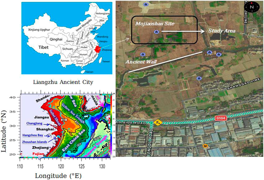
FIGURE 1. The study area’s location is in the Yangtze River’s lower reaches, Liangzhu Site, Zhejiang, South-eastern China.
The Liangzhu Culture flourished between 5,400 and 4,300 years ago, though, by the time it reached its zenith, it had disappeared from the Taihu Lake area. In the 1930s, archaeologists discovered the first indications of Neolithic culture as well as a huge portion of gemstone (Shi, 1938; Li et al., 2010). Between 7,600 and 6,600 calyr BP, flood plain inundation or tropical storms caused deposits in zone 5 in the Liangzhu City area rather than direct maritime submergence. The Liangzhu City area was indeed a lagoon with some soil salinity until about 5,100 years ago when it became best suited for Ancient settling and agriculture (Ling et al., 2021). Recently, in the South-Eastern corner platform, the prehistoric massive concrete layer about 10 m thick, and a charred soil sheet compounded slag and briquettes powder was discovered. The layer might have developed due to an ancient fire or religious events; however, the cause is currently unclear.
Prior GPR research has provided a small amount of information about the Liangzhu site’s encased prehistoric culture and identity due to the impact of moisture content on clay-rich soil types. Previously, the experimental studies failed to image a 1 m deep layer of stone blocks with an average diameter of more than 20 cm, which include 1 GHz and 500 MHz with a trace distance of 0.01 m and 250, 200, and 100 MHz with a trace range of 0.05 m (Lizan et al., 2019).
We focused on the rammed Earth platform and used polarization data acquisition and attribute-based data processing techniques to assess the suitability of non-traditional GPR methods for studying prehistoric archaeological targets in difficult subsurface conditions.
GPR data of the test site is acquired at a frequency of 100–200 MHz. The data is recorded at07 profiles, with a spatial spacing of 0.1 m between two shot points and a total distance of each profile is 20 m by using Pulse_EKKO PRO System (Sensors and Software Inc.) (Figure 2A). GPR polarization is an important technique for GPR surveys, especially when one needs to determine the shape, orientation, size, and exact location of any buried object. A linearly-polarized incident GPR wave experience polarization change upon scattering from the host medium, which highly depends upon the technique and antenna orientation, used for the acquisition of the GPR data. GPR electromagnetic field has a vector nature which is commonly associated with polarization. Pulse EKKO PRO system is used during data acquisition and is only displayed to show the line orientation, offset, and time window used for GPR data acquisition. Complete data acquisition parameters are shown in Table 1. The total length of the lines has been kept at 20 m each. Because the polarization effect offset plays an important role, therefore we tried three different offsets (0.1, 0.2, and 0.3 m). However, we found that 0.1 m offset gave us a much better quality subsurface image therefore we acquired the data with a 0.1 m offset.
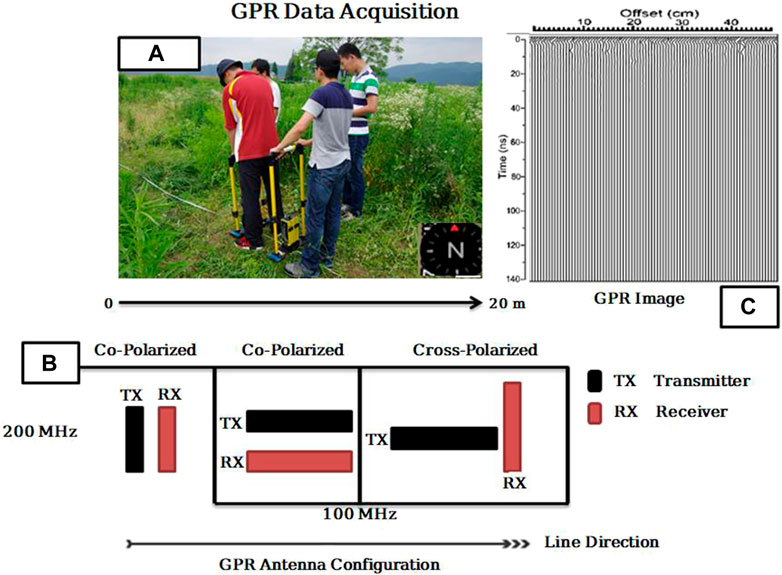
FIGURE 2. (A) GPR survey with 100–200 MHz antennas; (B) Antenna configurations used in the GPR study on the archaeological test site. The transmitting and receiving antennas are represented by black and red blocks, respectively. The antenna offsets for the 200 and 100 MHz bands are 0.5 and 1 m, respectively; (C) topography GPR image.
Unwanted effects from tree roots were predicted 9.1 m from the start of the GPR profile, at the location of a small peach tree, therefore we used three antenna configurations to take advantage of polarization effects caused by antenna, target, and tree root orientation (Figure 2B). The figure shows that our experimental geometry is co-polarizing for the 200 MHz frequency survey and cross-polarizing for the 100 MHz survey. Because our step size is nearly zero, the receiving antenna must move precisely to adjust the offset. Furthermore, rather than using a single frequency of antennas, we concentrate on connecting different antennas during the investigation. The signal generator in our detecting mode is a 200 MHz antenna, and a lower 100 MHz antenna is utilized in signal reception. As a result, the images are of good quality, and high resolution is predicted to attain during data processing analysis. Figure 2C depicts the topographic image of GPR data.
GPR data processing is the most important step in this study, which has been carried out in three steps, which is discussed as;
The purpose of this section is to provide a comprehensive understanding of GPR data processing techniques to the reader. More than 100 swaths were used to create the 3-D GPR data volume, which had a 100*120 m extension. Due to earlier excavated areas with ancient Liangzhu walls, boreholes, and little peach trees, the dataset was infrequent. First, using the GPR-Slice software (Geophysical), which has been specifically created for data processing and analysis of volume data, we applied a normal processing flow that also included bandpass filtering, editing, Dewow, sec and spherical divergence correction, amplitude recovery processing. To address specific data issues, especially the time unevenness between adjacent traces, specialized algorithms implemented in Matlab were used. The operator manually selected rectangular grids (chunks) within which swaths were interpolated, the complete processing flow chart is shown in Figure 3B.
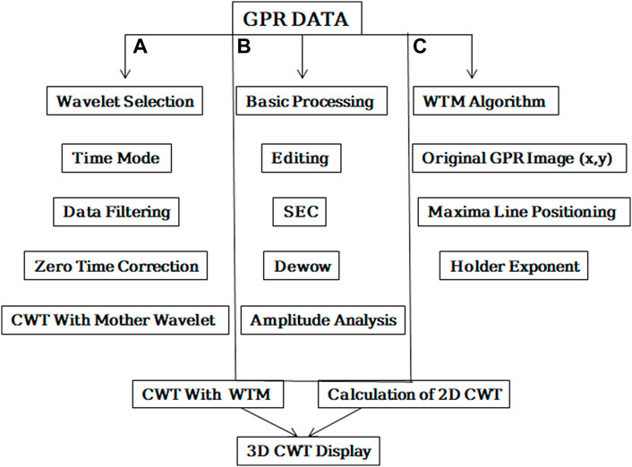
FIGURE 3. Showing data processing (A) conventional GPR data processing for the radar Gram display, (B) Overall GPR data processing methodology and CWT application (C) The WTMM’s flowchart.
CWT creates a time-scale map by dilation and translation of a wavelet. A single scale encompasses a frequency band and is inversely proportional to the dilated wavelet’s time support (Sinha et al., 2005; Sokolov, 2014). The method followed is mainly focused on the processing of GPR data and the use of the CWT methodology Figure 3A. Ultimately, using the CWT methodology, a coupled evaluation of conventional GPR data interpretation and understanding of GPR output was attempted. Standard procedures were used to process GPR data in point and time mode at first. Time zero correction was used to correct the signal position caused by the gap between the antenna and the subsurface. The signal has been enhanced using boxcar filtering, which removes various types of noise from the signal.
When using wavelet analysis as a tool to process signals from non-destructive diagnostics devices, engineering structures or their components are typically being monitored for condition. A continuous wavelet transform application in a vibration-based damage detection method for beams and plates is shown in the publication (Rucka and Wilde, 2006; Garbacz et al., 2017), the promising use of wavelet analysis of Impact Echo signals rating the effectiveness of concrete structure repairs is described. The processing of GPR data can be the same for any exploration but the interpretation is always different as per the requirements of the experimental data that is why we used the WTMM to extract topographical information from 3D GPR data in this section. The flow chart for this method is shown in Figure 3C.
Given the fact that many methodologies have been postulated, filtering unwanted files with wavelet analysis would be complicated because noises can substantially obstruct ground penetrating radar (GPR) signals. Noise levels are obtained by the probe, especially from deep locations, and they may obscure reflections due to signal attenuation at low altitudes. This article addresses the use of wavelet transform as one of the useful methods for data analysis. In the case of GPR signals, nevertheless, wavelet analysis would be difficult. It is indisputably necessary to note wavelet function, degradation level, cut-off point estimation method, and threshold transformation when de-noising and investigating signals; they must be carefully chosen because they have a significant impact on the results.
CWT is distinguished by the use of a set of basic functions known as wavelets that are well-localized (have compact support) in both time and frequency (Argoul et al., 1989). The Fourier Transform, on the other hand, has only “mono-localization,” meaning it cannot be localized in both time and frequency at the same time. The CWT of a function is written as
In Eq. 1, a is a scalar quantity, and b is the translation whereas
In general, the analytical function (z) is chosen to be spatial and temporal and the amplitude of the wave is confined. Usually, (z) only needs to have a zero mean, but for multi-resolution analysis, it also needs to be uncorrelated to some low order polynomials of degree n1 to have n receding moments:
Eq. 3 explains the p order moment of the wavelet coefficient at the scale of a, which replicates the computed parameters. Whereas filtering out trends, the wavelet transform demonstrates a signal’s distinctive features, particularly its singularities. The wavelet transform is shown to demonstrate the local properties of S at a point x 0. We have the power-law relationship, which is shown below (Morlet et al., 1982).
Where
The derivative of a Gaussian probability density function at time t yields the Gauss wavelet, which is complex-valued. It provides phase information and can be written by taking the path derivative function f;
Here,
The fractal dimension DF, which itself is linked to the Hurst exponent H, which statistically meaningful characterizes global surface roughness, has been used in most fractal techniques used to analyze geophysical impulses. To account for possible fluctuations in the rough surface’s local regularity, the multifractal formalism uses the Holder (local roughness) exponent h(r) of the function f (r), for whom the plot describes the rough surface under exploration (Kestener, 2003).
The 2D WTMM method can be used to calculate the D(h) singularity spectrum, which is defined as the Hausdorff dimension of the set of points r with the local roughness exponent h(r) equal to h. Let us define the two waves as
This is the basis of integration of CWT and WTMM where θ(x,y) function of smoothing. Let us suppose that θ as a Gaussian
This WTMM is found on connected chains when analyzing rough surfaces. This WTMM is divided up along linked curves along with all scales. From the start, the WT skeleton described by these maxima lines continues to hold all details about the hierarchical organization of the function f (r) singularities.
We have reached the point in the process where we must put the method into action, show the results, and discuss them. Before that, we’ll go over how the wavelet transforms method was implemented using the WTM and CWT integration in this section. The main challenge of the study is to detect the archaeological site using anomalies and make it visible with as much precision as possible. As we can see in (Figure 3C), the map is not conclusive, and nothing is visible on it. WTMM was applied to the data for this purpose. To solve the previously described problem, we analyzed the GPR image using the wavelet transform modulus maxima lines WTMM. The analyzing wavelet is the Mexican Hat.
The continuous wavelet transforms the modulus at the scale. The scales changed according to a power law (Siu and Constantinides, 1984);
Here,
The mathematical Eq. 11 shown above is the final version of the derived mathematics that can be used to extract the following data for the ongoing study of CWT and WTMM integration.
And
That will give us
The maxima of the modulus of the continuous wavelet transform are calculated using the first and second derivatives. These maxima are determined for each scale. Figure 4A shows GPR signals used for the wavelet transform; it can be seen that signal is compressed and dense because the intensity of the reflected signal is determined by the contrast between the adjacent layers, with higher contrast resulting in a stronger reflected signal. The continuous wavelet transform creates a time-frequency illustration of a signal, which provides time and frequency localization. The CWT is the convolution of a signal with the mother wavelet’s time version. Wavelet scale refers to the stretching and shrinking of the wavelet; a smaller scale factor results in a more compressed wavelet. When there are abrupt changes, the signal position that results from the space between the antenna and the subsurface has been corrected for time zero. By removing various forms of noise that were embedded in the signal, filtering has been used to improve it. The overburden depth, width, and position of the buried materials have been identified after all necessary processing steps have been applied.
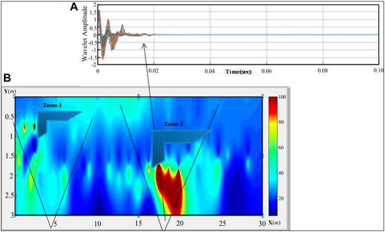
FIGURE 4. A 2D continuous wavelet transform of GPR data (A) mother wavelet application for continuous wavelet transform modulus (B) topographic GPR illustration of an archaeological test site with two marked zones named zone-1 and zone-2 which are the target area of this study.
The resulting set of maxima for all arranged scales is depicted in Figure 4B. It is referred to as the CWT skeleton. This will be used to detect anomalies using machine learning. As stated previously in the study, this map does not accurately represent topography and orientation. To solve the problem, an advanced processing tool is required. Structures are barely visible, but the spark and amplitude remain unclear; CWT will be advanced to 3D display which will further increase the impact of this study. The goal of this study is to identify the marked anomalies labelled zone-1 and zone-2. The contrast of the anomalies is always increased, and these areas are referred to as the Highs. Figure 4B was obtained in the coordinate projection system, which means that no physical quantity is involved, and these zones must be verified for physical quantities such as time and depth; further investigation of this study will focus on these two zones, which were detected anomalies on the archaeological test site.
To begin, a continuous mode survey was carried out to determine the precise location of the underlying buried material of the archaeological test site. In the following section, we have suggested the results for orientation, and exact location of underlying buried archaeological remains; we linked points of maxima using WTMM. The maximum points are crossed by the line curve that has been drawn. Exponents estimated at the modulus of CWT maxima are depicted in this section as well. The amplitudes and slope analysis can be determined using the local exponent. A general idea of access during the 3D GPRprospect realization can be obtained from the map of the set of these exponents.
Additionally, a wavelet has been chosen for CWT analysis at approximately the same time depth. At varied sub-bands, we have used a diverse range of mother wavelets, including Haar, Gauss, and Daubechies. For the same GPR scan, mother wavelets at various decomposition levels react differently. To solve this issue, each decomposition level has been subjected to CWT, and the mother wavelet has been chosen based on the maximum normalized mean power value of the wavelet coefficients. Only the maximum normalized mean power value of the wavelet coefficients for each mother wavelet has been shown as the outcome of CWT on GPR data.
The results were unclear when the Haar wavelet transform was applied to the data, so the Daubechies wavelet analysis was performed alongside Gauss and db3 for data interpretation. Nonlinear signal deposition into typical as an estimate and differencing as details are also used in the Daubechies wavelet, which is a revised and generalized version of the Haar transform. It has the advantage of being easier to implement and flip than Haar. The transformation uses four-level wavelet scaling functions or coefficients, which are rotted away into two sets of average c(n) and differenced (n) by a series of wavelet decomposition (Watson and Addison, 2002; Idi and Kamarudin, 2012).
Where
If the input signal x(n) is sequential, the local average c(n) will also be linear, but the local differential d(n) will be zero in this type of basis function. The transform is efficient for noise removal because it provides linear signals sparingly. When noise is whittled down, the amplitude gain and signal-to-noise ratio both increase making anomaly detection easier. The process is carried out in image processing by applying a 1-D wavelet transform to each row of pixel values in the image, which results in a horizontal approximation and details. After that, the process is repeated for each column, yielding vertical approximations and details (Afshari-Jouybari and Farahnaky, 2011).
Since the GPR data is acquired for two different types of frequencies, therefore, we have implemented CWT to each dataset separately. First, we’ll look at the data collected with co-polarized geometry at 200 MHz.
The image was analysed using the 2-D MATLAB wavelet toolbox. A four-ordered Daubechies (db-4) wavelet was computed for the horizontal, vertical, and diagonal details. Eqs 12, 13 were used to iteratively threshold the signals at various levels, with the intensity value below the threshold set to zero. Smaller amplitude wavelet coefficients were suppressed, but significant reflectance associated with larger anomalies was preserved. As a result, the image’s visibility improves, allowing for better observation of causative bodies’ locations. Not only are the anomalies clearer in 2D, but they are also more precise in 3D. Table 2 shows how several wavelet functions evaluate the reconstructed 100 MHz simulated signal up to six levels for signals masked with noise at the same level.
We found the reflection (R) in the 2D radar Gram, which was converted to the spark (S) in the 3D display, and we set the target area in each profile. The image is much better after applying CWT, but a comparative conclusion for anomaly detection has yet to be drawn. Therefore, it has a poor understanding of the distance travelled at any given instant. However, two edges that define the anomaly can be seen in both profiles. Because it is crucial to move the antenna at a constant speed (as the configuration was co-polarized for 200 MHz frequency), which is a function of the scan spacing (lateral resolution) of time-based data profiles, the GPR signature is not very clear in continuous mode (Figures 5A,D). We have used GPR data acquisition in point mode to pinpoint the precise location and overburden depth of the anomaly based on a continuous mode survey. The reflection events are clear in 2D profiles about 0.01 ns. The gain function for both the profiles confirms the anomaly detection in the 3D display. According to the ray theory, the principal GPR system’s conventional operation tends to result in resonance profiles, where the most of received signals are affected by reflections and diffractions from the subsurface due to heterogeneity. The system can also produce other radio wave types like direct waves in the air, and refracted waves. Because whenever CWT is applied we chose one specific wavelet which is called the mother wavelet as shown (Figures 5B,C) below as well. Application of CWT becomes easy and detection of the anomaly becomes further reliable.
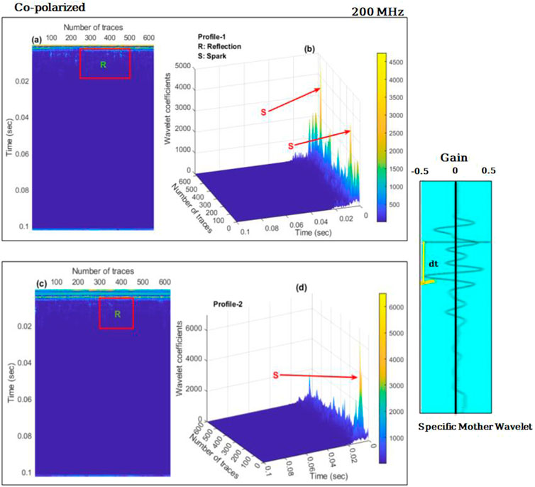
FIGURE 5. Continuous wavelet Transform (CWT) representation using co-polarized GPR data acquired at 200 MHz frequency, whereas (A) CWT in 2-D, where (R) represents the event reflection of profile 1. (B) After applying the CWT to 3-D GPR data In the figure, clear sparks (s) represent the buried archeology of the profile one test site (C) CWT in 2-D, where R represents the event reflection of profile 2. (D) 3-D representation of GPR data using the CWT in the figure, clear sparks (s) represents the buried archeology of the profile two test site. A specific mother wavelet with gain (−0.5- 0- + 0.5) is used for CWT.
The wavelet transform is used to detect anomalies in radar images even though radar signal energy is largely focused on a small set of measurements with fairly large coefficients. The wavelet coefficient energies of the context soil, on the other side, are scattered over a significantly bigger number of coefficients. In the transformed specifics images, the smaller coefficients are set to zero, uncovering the most vital information about better signal reflectors. The response of a point mode 100 MHz antenna with co-polarized geometry to GPR over a test site is shown in Figure 6. The edges (E1 and E2) in Figure 6A were identified at the same profile distance, with a 2 m width and depth of soil mass, and the results were nearly identical to those obtained with a 200 MHz antenna in point mode. The rectangular blocks (R) and the reflection events observed in Figures 6A,B confirm the underlying buried object at the archaeological site. These reflections are caused by the reverberation of the GPR reflected wave.
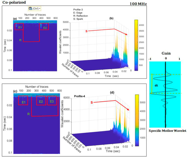
FIGURE 6. Continuous wavelet transformation (CWT) representation using co-polarized GPR data acquired at 100 MHz frequency, where (A) 2-D display of post-applied CWT E1 and E2 are the representation of the archeological edges, while rectangular R is the reflection event that appeared due to anomaly detection; and (B) post-application of Wavelet transform to the 3-D GPR data S defines the spark at the time mode, and these sparks are associated with the buried subsurface objects. (C) 2-D display of post-CWT E1, E2, and E3 are the archeological edges, while rectangular R is the reflection event that occurred as a result of anomaly detection. (D) After applying CWT to 3-D GPR data, S represents the spark in time mode; these sparks are associated with buried subsurface objects. The figure also includes a selected mother wavelet.
Figures 6B,D represent the spark that occurred at the same time mode of reflection event, in other words, two anomalies can be detected when CWT is used for 3-D display. Minor sparks can also be seen, particularly in Figure 6D, which can be attributed to subsurface heterogeneity and overburden pressure, which always damages the buried martial and cause various minor reflection events. Based on the interpretation of the GPR data, we chose a horizontal wavelet of approximately the same time depth as the anomalies were detected. CWT was applied to the selected GPR wavelet using various mother wavelets, as shown in the figure.
To test the method’s accuracy, we switched the antenna configuration from co-polarized to cross-polarized, and the frequency was reduced from 200 to 100 MHz for both transmitting (TX) and receiving (RX) antennas. Figure 7 represents all those events that have been discussed in the previous results for example (E1, E2) are the edges while (R) is the reflection event shown n Figure 7A, (S) is the representation of the anomaly sparks displayed in 3-D display Figures 7B,D and only one (R) reflection event can be observed in Figure 7C. In this type of configuration and frequency, the resolution of the sparks and anomalies is very low. Reflection events that were observed when using a frequency of 100 MHz and co-polarization are absent when using a frequency of 100 MHz and cross-polarization geometry. Moreover, when we compare the frequencies and polarized nature of GPR data, we discovered that co-polarization at 100 MHz provided better resolution after applying CWT and WTMM maxima, better reflection events, and better anomaly detection.
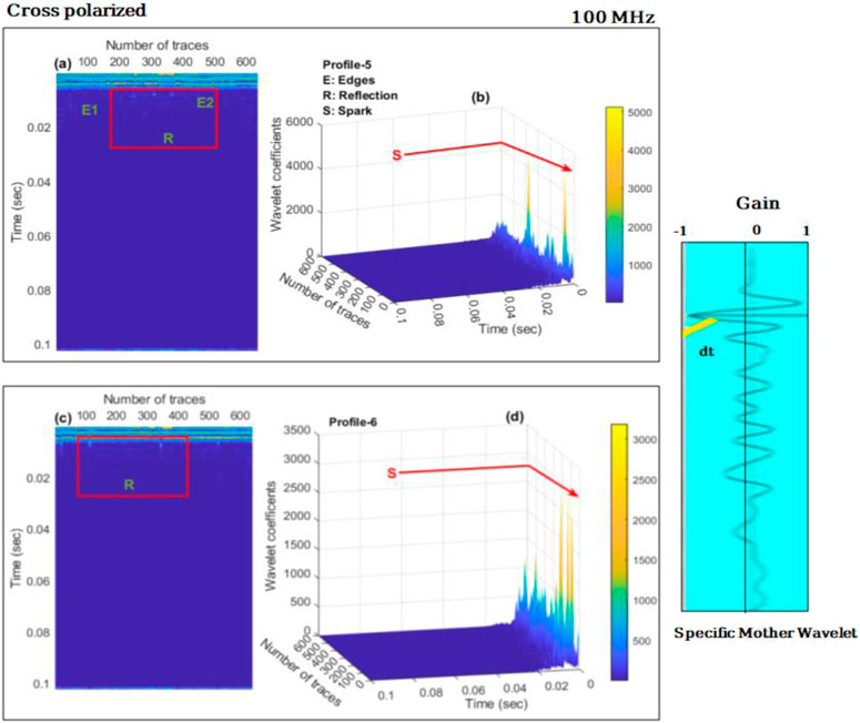
FIGURE 7. Continuous wavelet transformation (CWT) representation with cross-polarized GPR data acquired at 100 MHz frequency, where (A) 2-D display of post-applied CWT E1 and E2 are the representation of the archeological edges, while rectangular R is the reflection event that surfaced as a result of anomaly detection; and (B) post-application of Wavelet transform to the 3-D GPR data S defines the spark at the time mode, and these sparks are connected to the buried subsurface objects. (C) A rectangular R represents the reflection event that happened as a result of anomaly detection. (D) When CWT is applied to 3-D GPR data, the spark in time mode is represented by S; these sparks are connected to bury subsurface objects. A chosen mother wavelet is also shown in the figure.
The GPR results from various amplitudes should not be compared without extreme care for two primary reasons. First, multiple GPR units with multiple data transmission powers or centre frequencies may be used to collect the GPR data. Furthermore, various gains might be selected when gathering data, even if the data have been collected using the same GPR equipment. While comparing GPR data obtained from antennas tuned to different frequencies is inappropriate, it is assumed that data obtained from antennas tuned to the same frequency or from the same GPR unit will compare fairly well. In this section we will discuss how many decomposed levels the engineering discipline’s operator needs to choose for the correct balance of detail termination, to prevent losing critical information that might be disguised by noise in the high incidence component of the signal. The phases of breakdown range from one to eight (maximum breakdown stage, × = log2n, where (n) is the extent in time-domain signal illustrations). We must also determine the threshold below which the altitudes of the signal under investigation should be discarded (Javadi and Ghasemzadeh, 2017). In wavelet analysis, selecting the appropriate decomposition level is critical to the reconstruction process. A masked sample signal was generated to demonstrate how the de-noising process works; the original GPR signal is shown in Figure 8. A traditional frequency filter called an elliptic filter was used to filter the GPR signal for comparison.
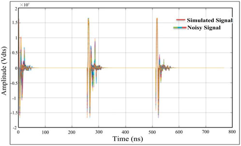
FIGURE 8. The mother wavelet is a simulated and noisy GPR signal that will be used for the CWT wavelet transform.
Figure 9 also shows how we were able to extract sample signals for our archaeology test site to investigate a wider range of antenna frequencies suitable for near-surface investigation. The mathematical representation of electromagnetic waves transmit in both time and space, as explained by the differential form of Maxwell’s equations is extensively used in the FDTD modeling techniques of the GPR signal (Balanis, 1989). The FDTD method’s complete principles and methods are reported in (Cassidy and Millington, 2009). This includes the three-line combined data from 0 to 0.02 ns, and there is the breakdown in one line that shows the break of the reflector because of the break in the ancient Liangzhu wall. The results show three-line data when CWT is applied with WTMM On the longitudinal survey lines 1,2, and 3, characteristic points Zone-1 and Zone-2 are two prominent extreme points on the CWT curves of single-channel GPR signals. Between the two characteristic points, the time difference is 0.585 ns. The height values of void fillers are calculated and shown in the results, as the GPR detection reflection time is a two-way travel time. This amplitude analysis also resembles with 2-D and 3-D display of CWT at the exact time point. Furthermore, it can be observed that with maximum amplitude analysis it has been demonstrated that adding a threshold to a noisy signal’s wavelet coefficients enables the restoration of the original signal’s smoothness. The procedure involves breaking down the data into an orthogonal wavelet basis, suppressing wavelet coefficients below a predetermined threshold, and then reassembling the data into its original domain.
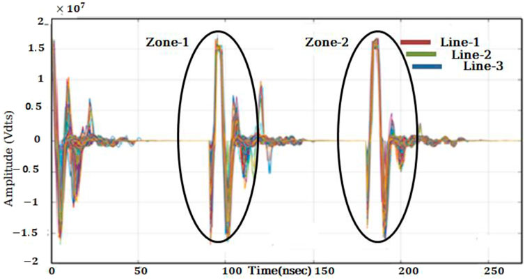
FIGURE 9. Transformed simulated signals at 100 MHZ frequency of combined three lines after editing in which time is included from 0 to 0.2 ns, which shows the maximum and minimum amplitude simultaneously, which is the anomaly of our study site Zone 1 and Zone 2 represent the anomalous body that is also called the target area of the test site.
Extensive analysis of the study reveals that the wavelet basis of the Daubechies is a good and compact choice for archaeology exploration, with a high degree of regularity when compared to the others. We used the db3 to obtain the module curve of the three different lines, which are line 1, line 2, and line 3, and applied it to the same wavelet we obtained earlier in the study to obtain the module of wavelet coefficients. The results are depicted in (Figures 10A–C). Derived from the analysis of the GPR data, we chose a longitudinal wavelet of e the same time depth as buried material was marked as the zone 1 and 2. CWT was applied to the selected GPR wavelet using mother wavelets. The plots of the relatively stable mean power of the Gauss and Daubechies mother wavelets are shown in Figures 10A–C. The maximum normalized mean power of CWT coefficients is connected with the Gauss mother wavelet at decomposition level 6 and the Daubechies mother wavelet at decomposition level 3. (db3). The module coefficients after CWT at db3 for the different lines are not the same, and the times obtained are also different, as seen in the results. The reason for this is that each wavelet has unique frequency localization properties. It is difficult to obtain an accurate signal by comparing these curves when using the db3 modules. Furthermore, the resolution and amplitude are not very effective.
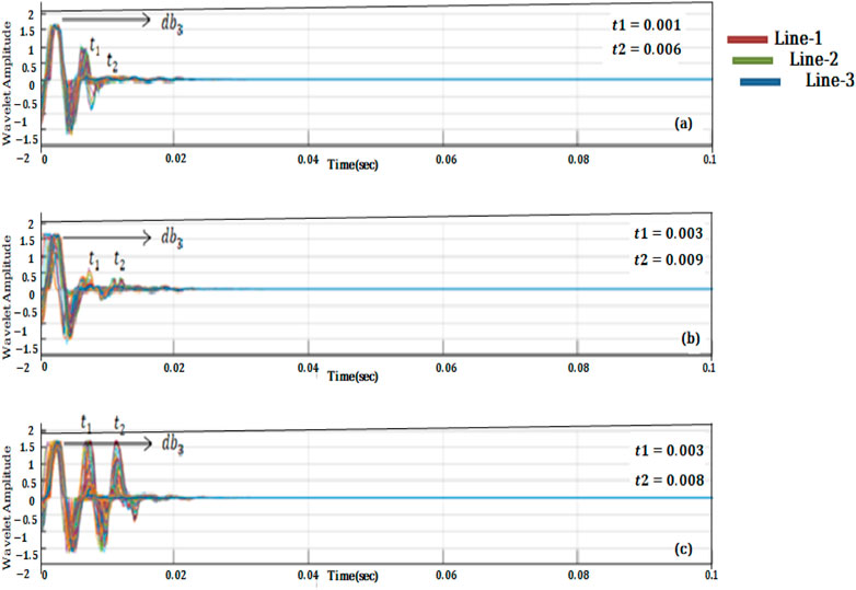
FIGURE 10. For (A) a typical single-channel signal on the survey line 1: db3 wavelet basis, the wavelet transforms coefficient module curves obtained by using different wavelet bases. (B) Wavelet basis of a typical single-channel signal on survey line 2: db3. (C) db3 wavelet basis for a typical single-channel signal on survey line 3.
Because only two zones of interest have been marked to detect the archaeological prospection, only two-time levels have been chosen as t1 and t2 in each wavelet composition. Furthermore, db3 is insufficient for detecting the anomaly.
The stretch factor has a major impact on the wavelet transform results when using the wavelet transform modulus maximum method for evaluating the bifurcation characteristics of a GPR signal. When the stretch factors are 2, 4, 6, and 8, and the modulus curves of wavelet transform coefficients are acquired, the db5 wavelet basis is used to operate wavelet transform on the GPR signal on survey lines 1–3. Figure 11 represents the results. As shown in Figure 11, the wavelet transform coefficient modulus curves obtained at different stretch scales are not exactly equivalent. As a result, when applying the wavelet transform to the GPR signal, the stretch factor differs, as does the GPR signal’s obtained singularity. Finally, when the modulus curves of Figure 10 are compared to the modulus curves in Figure 11, the proposed CWT method yields a higher resolution curve than the wavelet transform modulus maximum method. At the maximum deformation value, the depth was predicted using the CWT technique for all mother wavelets. The depth level is equitable to the deformation scale db5,6, culminating in the same burdening depth value (1.8 m) for all mother wavelets. The total number of scans collected for the profile is 200; with three scans per 1 m distance (scan/unit is 3). By subtracting both scan values and then dividing by 3 we can calculate the deformation level for any GPR data. Figure 11B indicates test site boundaries between scan numbers 140 and 195. Similarly, the mother wavelet (Figure 11C) indicates boundaries between scan numbers 145 and 195. Because choosing an appropriate mother wavelet is critical for conducting CWT, we chose a mother wavelet with a high normalized mean power value.
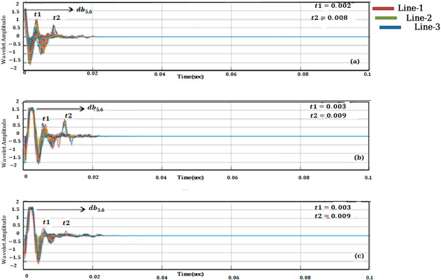
FIGURE 11. Modules curves of wavelet transform coefficients obtained by using wavelet transform for typical single-channel signal on survey lines 1, 2, and three are shown as (A–C) at various stretch scales: (A) = 1.9; (B) = 3.9; (C) = 5.9.
In this study, we chose mother wavelets at different decomposition levels. The normalized mean power of wavelet coefficient for Gauss and Daubechies mother wavelets is highest at levels db6 and (db3), which are then used for CWT. The same overburden depth of the buried materials is indicated by CWT using all three mother wavelets, which is approximately 1.8 m.
The wavelet transform is used to detect anomalies in radar images since the considerable amount of energy in a radar signal is largely focused on a small set of dimensions with large coefficients. On the other side, the energies of the wavelet coefficients in the reference soil are scattered over a larger number of coefficients. The smaller coefficients in the transmogrified details images are set to zero, showing the most vital information regarding strong signal reflectors. For all antenna frequency pairs and noise levels, the idea was to build a maximum push line that might better differentiate the wavelet function that yields the maximum amplitude. When going to compare functions, the best function would have to have the minimum signal and coefficients.
The proposed technique has a high level of robustness in resolving this issue and can help with the 3D GPR design. In our study, we first demonstrate the continuous wavelet transform’s sensitivity to noise when solving the same problem of land topography with the same data. The next step is to figure out a solution to the problem. The preferred framework for small scales is based on using a digital filter at the modulus of the 2DCWT. The paper begins with a description of the 2D continuous wavelet transform’s principle, followed by an explanation of the problem. When the data was collected, the amplitude level of the signal was very low, making it difficult to find the mother wavelet to apply the CWT. As a result, we had to develop a technique to distinguish between signal and noise, so we used WTMM.
The final result of any research should provide conclusive evidence and depict a brief and comprehensive analysis of the entire study. Figure 12 depicts the entire outcome of this research. If you recall from previous sections, we marked two zones, zone-1 and zone-2, which are the buried archaeological remains in the test site. The theme of the study is anomaly detection using CWT, for which we separately conducted studies for the amplitude, 2D, and 3D visualization of the test site, and we discovered that Daubechies mother wavelet to level 6 gives a clear indication of the anomalous zone, as shown in Figure 12A. We observed the signal and two clear reflection zones as evidence of anomalies present in the subsurface using the mother wavelet in the 2D data analysis Figure 12B. For conclusive evidence, the same mother wavelet is used for 3D wavelet CWT with WTMM integration, and two zones that were predicted in previous sections of this study are detected.
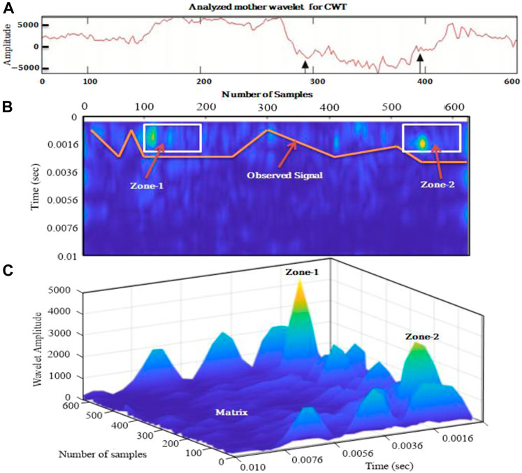
FIGURE 12. Combination of (A) mother wavelet used to analyze GPR data; (B) 2D anomaly detection with observed signal and two anomalous zones marked as zone-1 and zone-2; and (C) 3D visualization of the archeological test site with clear two anomalous zones with color contrast marked as zone-1 and zone-2, same color contrast is an unmarked zone which represents the matrix present in the subsurface.
The use of WTM and CWT distinguishes this study from earlier studies that were mostly used in seismic exploration. It is critical to understand that WTM and CWT are both wavelet transforms, and they both reduce noise and increase signal amplitude if both are applied carefully to synthetic data, they will produce much better results than conventional processing. Furthermore, WTM is used to clear the subsurface image and distinguish the anomaly region, whereas CWT is typically used to process individual signals to complete signal processing with the help of the mother wavelet.
Wavelet analysis has been proven to be helpful in the research of ground-penetrating radar results. Mother wavelet function sampling, discretization level, wavelet threshold transformation, and threshold evaluation are some of the parameters that have been debated as attempting to influence wavelet-based performance. Data from two GPR antenna frequencies have been used to investigate signals obscured by low, medium, and high noise to evaluate a particular case scenario. It should be concluded that the proposed technique can remove the noise signature from the 2D CWT’s plotted maxima. An effective tool that can retrieve a great deal of knowledge well about physics and attributes of the Earth is the evaluation of GPR data using the spectral framework revived by the continuous wavelet transform. To confront more geophysical problems, we advise applying the wavelet transform modulus maxima lines to more GPR data. We recommend incorporating the presented concept when using continuous or discrete wavelet transforms to analyze 2D or 3D GPR data. While using the wavelet transform to analyze raw GPR data, bear in mind that direct low pass filtering can eliminate many high-frequency pathogenic sources. A maximum of two and a minimum of six spectral levels are highly suggested. We suggest implementing three levels of putrefaction to account for low-energy reflections.
The data analyzed in this study is subject to the following licenses/restrictions: The data is confidential. Requests to access these datasets should be directed to aWJyYXJpcWJhbEBnbHV0LmVkdS5jbg==.
Conceptualization, II; methodology, II; software, II and AA; validation, XB, GT and PS; formal analysis, XB; investigation, II and XB resources, XB; data curation, GT and AE; writing―original draft preparation, II; writing―review and editing, AA and AE; visualization, II; supervision, XB; project administration, XB; funding acquisition, XB, XH, GW, UA and AA reviewed the manuscript and provided the necessary suggestions. XH, PS helped in processing the data and formatting. All authors contributed to the article and approved the submitted version.
This research work is sponsored by National natural science foundation of China (42174080and41674075) and Guangxi Natural Science Foundation of China (GXNSFGA380004).
Authors would like to extend my gratitude to the School of Earth Sciences Zhejiang University Hangzhou China for providing us the test site to acquire the data to complete this project. I am also grateful to reviewers who contributed their time and critical review of the article, making it more appealing to the geophysical community.
The authors declare that the research was conducted in the absence of any commercial or financial relationships that could be construed as a potential conflict of interest.
All claims expressed in this article are solely those of the authors and do not necessarily represent those of their affiliated organizations, or those of the publisher, the editors and the reviewers. Any product that may be evaluated in this article, or claim that may be made by its manufacturer, is not guaranteed or endorsed by the publisher.
Abd El-Raouf, A., Iqbal, I., Meister, J., Abdelrahman, K., Alzahrani, H., and Badran, O. M. (2021). Earthflow reactivation assessment by multichannel analysis of surface waves and electrical resistivity tomography: A case study. Open Geosci. 13, 1328–1344. doi:10.1515/geo-2020-0310
Afshari-Jouybari, H., and Farahnaky, A. (2011). Evaluation of Photoshop software potential for food colorimetry. J. Food Eng. 106, 170–175. doi:10.1016/j.jfoodeng.2011.02.034
Anees, A., Shi, W., Ashraf, U., and Xu, Q. (2019). Channel identification using 3D seismic attributes and well logging in lower Shihezi Formation of Hangjinqi area, northern Ordos Basin, China. J. Appl. Geophy. 163, 139–150. doi:10.1016/j.jappgeo.2019.02.015
Argoul, F., Arneodo, A., Elezgaray, J., Grasseau, G., and Murenzi, R. (1989). Wavelet transform of fractal aggregates. Phys. Lett. A 135 (6-7), 327-336.
Baili, J., Lahouar, S., Hergli, M., Al-Qadi, I. L., and Besbes, K. (2009). GPR signal de-noising by discrete wavelet transform. NDT E Int. 42, 696–703. doi:10.1016/j.ndteint.2009.06.003
Cassidy, N. J., and Millington, T. M. (2009). The application of finite-difference time-domain modelling for the assessment of GPR in magnetically lossy materials. J. Appl. Geophy. 67, 296–308. doi:10.1016/j.jappgeo.2008.09.009
Davis, J. L., and Annan, A. P. (1989). Ground‐penetrating radar for high‐resolution mapping of soil and rock stratigraphy 1. Geophys. Prospect. 37, 531–551. doi:10.1111/j.1365-2478.1989.tb02221.x
Diz-Mellado, E., Mascort-Albea, E. J., Romero-Hernández, R., Galán-Marín, C., Rivera-Gómez, C., Ruiz-Jaramillo, J., et al. (2021). Non-destructive testing and Finite Element Method integrated procedure for heritage diagnosis: The Seville Cathedral case study. J. Build. Eng. 37, 102134. doi:10.1016/j.jobe.2020.102134
Economou, N., Vafidis, A., Benedetto, F., and Alani, A. M. (2015). “GPR data processing techniques,” in Civil engineering applications of ground penetrating radar (Springer), 281–297.
Ehsan, M., Gu, H., Akhtar, M. M., Abbasi, S. S., and Ehsan, U. (2018). A geological study of reservoir formations and exploratory well depths statistical analysis in Sindh Province, Southern Lower Indus Basin, Pakistan. Kuwait J. Sci. 45 (2). doi:10.48129/kjs
Ehsan, M., and Gu, H. (2020). An integrated approach for the identification of lithofacies and clay mineralogy through Neuro-Fuzzy, cross plot, and statistical analyses, from well log data. J. Earth Syst. Sci. 129, 101–113. doi:10.1007/s12040-020-1365-5
Forte, E., and Pipan, M. (2008). “GPR rock mass imaging and characterization by attenuation analysis,” in 70th EAGE conference and exhibition incorporating SPE EUROPEC 2008 (European Association of Geoscientists & Engineers), cp-40.
Garbacz, A., Piotrowski, T., Courard, L., and Kwaśniewski, L. (2017). On the evaluation of interface quality in concrete repair system by means of impact-echo signal analysis. Constr. Build. Mat. 134, 311–323. doi:10.1016/j.conbuildmat.2016.12.064
Goyal, P., and Tiwari, V. M. (2014). Application of the continuous wavelet transform of gravity and magnetic data to estimate sub‐basalt sediment thickness. Geophys. Prospect. 62, 148–157. doi:10.1111/1365-2478.12053
Idi, B. Y., and Kamarudin, M. N. (2012). Interpretation of ground penetrating radar image using digital wavelet transform. Asian J. Appl. Sci. 5, 174–182. doi:10.3923/ajaps.2012.174.182
Iqbal, I., Bin, X., Tian, G., Wang, H., Sanxi, P., Yang, Y., et al. (2021). Near surface velocity estimation using GPR data: Investigations by numerical simulation, and experimental approach with AVO response. Remote Sens. (Basel). 13, 2814. doi:10.3390/rs13142814
Iqbal, I., Tian, G., Bin, X., and Wang, Z. (2022). GPR antennas geometry and its impact over detection of near-surface water contamination through AVO Data analysis at laboratory site. J. Appl. Geophy. 205, 104758. doi:10.1016/J.JAPPGEO.2022.104758
Iqbal, I., Tian, G., Liu, Y., and UsmanKhan, M. (2018). Theoretical investigation of low conductive NAPL using (AVO) analysis of GPR data," in Signal processing in geophysics. Zhejiang, China: Zhejiang Signal Processing Society.
Iqbal, I., Tian, G., Wang, Z., Masood, Z., Liu, Y., Zhao, W., et al. (2020). Symmetry between theoretical and physical investigation of water contamination using amplitude variation with offset analysis of ground-penetrating radar data. Symmetry (Basel). 12, 991. doi:10.3390/sym12060991
Javadi, M., and Ghasemzadeh, H. (2017). Wavelet analysis for ground penetrating radar applications: A case study. J. Geophys. Eng. 14, 1189–1202. doi:10.1088/1742-2140/aa7303
Kestener, P. (2003). Analyse multifractale 2D et 3D à l’aide de la transformation en ondelettes: Application en mammographie et en turbulence développée. Université Sciences et Technologies-Bordeaux I. Doctoral dissertation.
Kuloglu, M., and Chen, C.-C. (2010). “Ground penetrating radar for tunnel detection,” in 2010 IEEE International Geoscience and Remote Sensing Symposium, Honolulu, HI, USA, 25-30 July 2010 (IEEE), 4314–4317.
Kumar, S., Pal, S. K., Rani, S., and Saurabh, H. (2020). GPR data interpretation using continuous wavelet transform: A different approach. Curr. Sci. 118, 1104. doi:10.18520/cs/v118/i7/1104-1111
Lampropoulos, K. C., Moropoulou, A., and Korres, M. (2017). Ground penetrating radar prospection of the construction phases of the Holy Aedicula of the Holy Sepulchre in correlation with architectural analysis. Constr. Build. Mat. 155, 307–322. doi:10.1016/j.conbuildmat.2017.08.044
Lee, K., Szerbiak, R., McMechan, G. A., and Hwang, N. (2009). A 3-D ground-penetrating radar and wavelet transform analysis of the morphology of shoreface deposits in the Upper Cretaceous Ferron Sandstone Member, Utah. Am. Assoc. Pet. Geol. Bull. 93, 181–201. doi:10.1306/09230808018
Li, Y., Wu, J., Hou, S., Shi, C., Mo, D., Liu, B., et al. (2010). Palaeoecological records of environmental change and cultural development from the Liangzhu and Qujialing archaeological sites in the middle and lower reaches of the Yangtze River. Quat. Int. 227, 29–37. doi:10.1016/j.quaint.2010.05.015
Ling, G., Ma, C., Yang, Q., Hu, Z., Zheng, H., Liu, B., et al. (2021). Landscape evolution in the Liangzhu area since the early holocene: A comprehensive sedimentological approach. Palaeogeogr. Palaeoclimatol. Palaeoecol. 562, 110141. doi:10.1016/j.palaeo.2020.110141
Liu, Y., Irving, J., and Holliger, K. (2022). High-resolution velocity estimation from surface-based common-offset GPR reflection data. Geophys. J. Int. 230, 131–144. doi:10.1093/gji/ggac058
Lizan, A., Tian, G., Wang, Y., Chen, R., Shaihk, S., and Liu, H. (2019). Detection of a thin layer by seismic reflection with different geophones at a site in Liangzhu, Southeastern China. Arab. J. Geosci. 12, 752–759. doi:10.1007/s12517-019-4778-1
Lualdi, M., and Lombardi, F. (2014). Combining orthogonal polarization for elongated target detection with GPR. J. Geophys. Eng. 11, 055006. doi:10.1088/1742-2132/11/5/055006
Major, J. S., and Cook, C. A. (2016). Ancient China: A history. 1st Edn. Routledge. doi:10.4324/9781315715322
Morlet, J., Arens, G., Fourgeau, E., and Glard, D. (1982). Wave propagation and sampling theory—Part I: Complex signal and scattering in multilayered media. Geophysics 47, 203–221. doi:10.1190/1.1441328
Ortega-Ramírez, J., Bano, M., Cordero-Arce, M. T., Villa-Alvarado, L. A., and Fraga, C. C. (2020). Application of non-invasive geophysical methods (GPR and ERT) to locate the ancient foundations of the first cathedral of Puebla, Mexico. A case study. J. Appl. Geophy. 174, 103958. doi:10.1016/j.jappgeo.2020.103958
Ouadfeul, S.-A., and Aliouane, L. (2010). “Multiscale analysis of 3D GPR data using the continuous wavelet transform,” in Proceedings of the XIII Internarional Conference on Ground Penetrating Radar, Lecce, Italy, 21-25 June 2010 (IEEE), 1–4.
Ouadfeul, S. A. (2006). Analyse de signaux de géophysiques par la méthode des maxima du module de la transformée en ondelettes MMTO. Alger: Université des sciences et de la technologie Houari Boumediène. Doctoral dissertation.
Rucka, M., and Wilde, K. (2006). Application of continuous wavelet transform in vibration based damage detection method for beams and plates. J. Sound. Vib. 297, 536–550. doi:10.1016/j.jsv.2006.04.015
Shi, X. (1938). Liangzhu: Preliminary report on pottery cultural site. Zhejiang Province, Hangzhou: Education of Zhejiang Province Press.
Sinha, S., Routh, P. S., Anno, P. D., and Castagna, J. P. (2005). Spectral decomposition of seismic data with continuous-wavelet transform. Geophysics 70, P19–P25. doi:10.1190/1.2127113
Siu, W.-C., and Constantinides, A. G. (1984). On the computation of discrete Fourier transform using Fermat number transform. IEE Proc. 131, 7. doi:10.1049/ip-f-1:19840003
Sokolov, K. O. (2014). Frequency-time presentation of georadar profiles based on continuous wavelet transform. J. Min. Sci. 50, 256–259. doi:10.1134/s1062739114020070
Trinks, I., Johansson, B., Gustafsson, J., Emilsson, J., Friborg, J., Gustafsson, C., et al. (2010). Efficient, large‐scale archaeological prospection using a true three‐dimensional ground‐penetrating radar array system. Archaeol. Prospect. 17, 175–186. doi:10.1002/arp.381
Watson, J. N., and Addison, P. S. (2002). Spectral-temporal filtering of NDT data using wavelet transform modulus maxima. Mech. Res. Commun. 29, 99–106. doi:10.1016/s0093-6413(02)00236-7
Wutke, M., Lejzerowicz, A., and Garbacz, A. (2020). The use of wavelet analysis to improve the accuracy of pavement layer thickness estimation based on amplitudes of electromagnetic waves. Materials 13, 3214. doi:10.3390/ma13143214
Zhao, W., Tian, G., Forte, E., Pipan, M., Wang, Y., Li, X., et al. (2015). Advances in GPR data acquisition and analysis for archaeology. Geophys. J. Int. 202, 62–71. doi:10.1093/gji/ggv121
Zhao, W., Tian, G., Wang, B., Forte, E., Pipan, M., Lin, J., et al. (2013). 2D and 3D imaging of a buried prehistoric canoe using GPR attributes: A case study. Near Surf. Geophys. 11, 457–464. doi:10.3997/1873-0604.2013029
Keywords: continuous wavelet transform (CWT), module maxima line, scalogram analysis, archaeogeophysics, ground penetrating radar (GPR), applied geophysics
Citation: Iqbal I, Xiong B, Tian G, Ali A, Peng S, Wen G, Huang X, Anees A, Ashraf U and Abd El-Raouf A (2022) Analysis of 2D and 3D GPR data interpretation using continuous wavelet transforms: Case study from an archaeological test site. Front. Earth Sci. 10:1008757. doi: 10.3389/feart.2022.1008757
Received: 01 August 2022; Accepted: 13 September 2022;
Published: 30 September 2022.
Edited by:
Muhsan Ehsan, Bahria University, PakistanReviewed by:
Muhammad Zubair, Slovak Academy of Sciences (SAS), SlovakiaCopyright © 2022 Iqbal, Xiong, Tian, Ali, Peng, Wen, Huang, Anees, Ashraf and Abd El-Raouf. This is an open-access article distributed under the terms of the Creative Commons Attribution License (CC BY). The use, distribution or reproduction in other forums is permitted, provided the original author(s) and the copyright owner(s) are credited and that the original publication in this journal is cited, in accordance with accepted academic practice. No use, distribution or reproduction is permitted which does not comply with these terms.
*Correspondence: Bin Xiong, eGlvbmdiaW5AZ2x1dC5lZHUuY24=; Umar Ashraf, dW1hcmFzaDIwMTBAaG90bWFpbC5jb20=
†These authors have contributed equally to this work
Disclaimer: All claims expressed in this article are solely those of the authors and do not necessarily represent those of their affiliated organizations, or those of the publisher, the editors and the reviewers. Any product that may be evaluated in this article or claim that may be made by its manufacturer is not guaranteed or endorsed by the publisher.
Research integrity at Frontiers

Learn more about the work of our research integrity team to safeguard the quality of each article we publish.