 Hao Yuan
 Taoli Xiao*
95% of researchers rate our articles as excellent or good
Learn more about the work of our research integrity team to safeguard the quality of each article we publish.
Find out more
ORIGINAL RESEARCH article
Front. Earth Sci. , 06 January 2023
Sec. Geohazards and Georisks
Volume 10 - 2022 | https://doi.org/10.3389/feart.2022.1007439
This article is part of the Research Topic A Multi-Disciplinary Study of Dynamic Triggering: Field Observations, Numerical Simulations, and Laboratory Experiments View all 6 articles
Composite rocks comprise the rock structures that are commonly used in geotechnical engineering. The fracture configuration has a substantial influence on the mechanical behavior, failure mode, and crack propagation of composite rocks. In this study, we considered a composite rock with two prefabricated coplanar fractures. Through laboratory uniaxial compression tests and using a digital image acquisition system, we systematically studied the effects of different fracture lengths and inclination angles on the mechanical properties and failure characteristics of the rocks. We obtained the following results: 1) during the loading deformation of the rock sample, the peak stress and elastic modulus increased with an increase in the fracture inclination angle and decreased with an increase in the fracture length. The deterioration coefficient k (the ratio of the difference between the peak strength of intact and fractured rock sample to that of intact rock sample) decreased with an increase in the fracture inclination angle and increased with an increase in the fracture length. 2) The failure type of the rock samples was primarily controlled by the fracture inclination angle and material of the two rock types, and the fragmentation degree was primarily controlled by the fracture length. With an increase in the fracture inclination angle, the failure mode of rock sample exhibited the following order of changes leading to failure: a double-Y type (trwo wing and one antiwing cracks appeared on each prefabricated fracture) → double-Z type (two wing cracks appeared on each prefabricated fracture) → Z type (one wing crack appeared on each prefabricated fracture). 3) The type of coalescence of the rock bridge was controlled by the fracture inclination angle and structural plane. The crack positions were primarily affected by the fracture length. 4) At a low fracture inclination angle (α ≤ 30°), the propagation of the microcracks showed aggregated band formation. Above moderate fracture inclination angles (α > 30°), the microcrack aggregation band gradually weakened and expanded in the direction of dispersion.
With the development of underground engineering, soft and hard composite strata are inevitably encountered (Liu et al., 2013; Yan et al., 2020). When underground engineering is conducted in composite strata, improper construction may cause engineering disasters, such as uneven stress causing the surrounding rocks to collapse, along with other potential risks (Wu et al., 2019). Studies on composite strata have primarily focused on tunnel construction (Rad and AYassaghi, 2004; Tang and Xu, 2016; Yang et al., 2018; Wang et al., 2019) and coal mining (Liu et al., 2015; Zhang et al., 2018). In addition, rock masses with different physical characteristics in composite rock strata have different strengths, permeabilities, and other mechanical properties. Among them, soft and hard composite rocks highly influence tunneling and the technology supporting tunnels, and therefore, additional requirements are considered for constructions in these rocks. To understand the influence of the mechanical properties of composite materials, researchers have studied the construction of a large-span tunnel within a composite stratum (Sun et al., 2018; Tu et al., 2020). Similar to a single rock, composite rock also possesses numerous microcracks, fractures, joints, holes, and other defects. The initiation, expansion, and penetration of these defects reduce the strength of the original rock and can even cause instability and failure of engineering rock mass, thereby affecting construction safety. Therefore, understanding the mechanical behavior and failure mechanism of fractured composite rocks has important engineering value.
Numerous studies have been conducted on the mechanical behavior and crack propagation evolution mechanism of fractured rocks. Yang (2011) performed uniaxial compression tests on sandstone and granite with two coplanar fractures, analyzed the sequence and types of crack propagation in brittle sandstone during deformation, and determined the influence of the coplanar fracture inclination angle on the strength and deformation behavior of sandstone samples. Huang and Yang (2019) conducted triaxial compression tests on granite with two coplanar fractures, analyzed the influence of the fracture inclination angle and confining pressure on the strength characteristics of granite samples, studied the internal fracture characteristics of granite samples using X-ray computed tomography (CT) scanning technology, and determined four typical crack transfixion types. Dong et al. (2020) performed Brazilian splitting tests on rock-like materials with two coplanar fractures, analyzed the influence of the fracture angle and filling on the tensile strength of the sample, and studied the crack propagation process of a sample with an acoustic emission and digital speckle system. The results showed that the tensile strengths of the filled and unfilled specimens gradually decreased with an increase in the fracture inclination angle. Zhang and Zhou (2020) conducted uniaxial compression tests on granite with double fractures and studied the fracture mechanism and acoustic emission characteristics of fractured rocks over time using acousto-optical monitoring technology.
Several researchers have also studied multifractured rocks. Zhou et al. (2019) and Zhou and Zhang (2021) used digital imaging and AE techniques to analyze the process of crack growth in granite with three fractures and found that the complete cracking process could be classified into six stages: (I) crack closure, (II) linear elastic deformation, (III) process zone nucleation, (IV) crack initiation and stable crack growth, (V) critical energy release and unstable crack growth, and (VI) failure and postpeak softening. Zhou et al., 2019 analyzed the influence of the brittleness of rock-like materials on crack initiation, propagation, and coalescence in three fracture-containing specimens through uniaxial compression test and digital image acquisition (DIC) and found that the crack initiation mode transforms from tensile to shear as the brittleness index of rock-like materials decreases. Zhou et al. (2014) conducted uniaxial compression tests on rock-like materials with four fractures and identified five types of cracks, including wing, quasi-coplanar secondary, oblique secondary, out-of-plane tensile, and out-of-plane shear cracks. Zhou et al. (2018) performed uniaxial compression tests on rock samples with nine prefabricated fractures, and combined with the results of DIC, they revealed the mechanism through which brittle and ductile multifractured rock mass fractured. The results showed that the type of crack initiation transforms from shear to tensile cracks as the brittleness index increases.
Some researchers have used numerical simulation software to study the influence of fractures on the mechanical behavior and failure characteristics of rocks. Tian et al. (2017) used particle flow software PFC2D to simulate the fracture process of brittle sandstone with two coplanar fractures under different confining pressures. They found that the peak strength generally increased with the inclination in the coplanar fractures and that the final failure of the sample primarily occurred owing to shear. Chen et al., 2020 conducted particle flow simulations on soft–hard interphase composite rock samples with two coplanar fractures and analyzed the influence of the strata inclination angle and fracture inclination angle on the mechanical properties and failure characteristics of composite rock samples. Yin et al. (2015) used RFPA2D software to simulate composite rock with a single fracture and studied the law of the variation in the macroscopic mechanical properties of rock samples with changing interlayer inclination angle when no fracture occurred under uniaxial compression at the fracture inclination angle (α) of 45° and 135°. They also analyzed the failure mechanism of a composite rock with a single fracture under uniaxial compression using acoustic emission. Wang et al. (2020) used the particle flow software PFC2D to simulate uniaxial compression test of rhyolite and analyzed the influence of the fracture inclination angle, fracture length and width, and rock bridge length on the failure characteristics of the fractured rock mass. In terms of two noncoplanar fractures, Li and Li (2013) and Zhang et al. (2017) performed numerical simulations on the failure process of two fractured goose-shaped rock samples and analyzed the influence of the rock bridge and fracture inclination angles on the characteristics of crack evolution and mechanical behavior of the rock samples. The above numerical simulations were primarily based on PFC, and researchers have primarily studied the influence of the existence of prefabricated fractures on the final failure mode of the rock sample and the mechanical parameters of the rock sample. Yang and Liu (2012), Yang et al. (2014), Huang et al. (2016), and Fu et al. (2019) conducted triaxial compression test simulations on rock samples with two fractures and found that, compared with long-fractured rock samples, short-fractured rock samples require a longer time to reach peak strength, revealing that the macroscopic secondary shear zone in rock primarily comprises tensile cracks and a small number of shear cracks.
In addition to these results for double-fractured rocks, many researchers have investigated single-fractured rocks. Xiao et al. (2012a) conducted a triaxial compression test on a single-fractured marble and proposed three types of cracks: tensile (type I), sliding (type II), and tearing (type III) cracks. Wang et al., 2020 performed uniaxial compression simulation on composite rock samples with a single fracture and explored the influence of the fracture inclination angle and length on the mechanical properties and failure mode of the rock. They found that the larger the fracture inclination angle or length, the smaller the fracture extension range on the side with weaker mechanical properties. The failure mode presented the transition characteristics of “X” → “y” → “>.” Zhang et al. (2019) analyzed the influence of the comprehensive action of the fracture inclination angle, length, and position on the strength and failure characteristics of rock and found that the fracture inclination angle had a considerable effect on the initiation position and time of new cracks. The fracture length correlated with the integrity and stability of the rock. The fracture position affects the scale of crack propagation and failure mode, and the influence on the peak strength is as follows: length > inclination > position. Xi et al. (2020) conducted uniaxial compression tests on deep granite with prefabricated fractures and found that with an increase in the fracture inclination angle, the wing crack propagation speed increased, and the new cracks were distributed in a clockwise direction.
Most of the abovementioned results have been obtained for a single rock type; however, similar studies on composite rock, particularly on the strength and crack propagation evolution of composite rock with fractures, are lacking. Considering actual engineering conditions, fractures typically appear in two kinds of rocks, which change the mechanical properties and failure modes of the composite rock and eventually cause engineering disasters or potential risks. The fracture inclination angle and length are the major factors influencing the mechanical behavior and failure mechanism of rocks. This non-negligible, primary influencing factor forms the basis of the studies of composite rock strata investigating the mechanical properties, failure mode, and crack propagation law of composite rock with coplanar fractures, with the aim of guiding engineering practice. Therefore, in this study, we selected prefabricated composite rock with coplanar fractures as the research object and determined the influence of the geometric characteristics of fractures on the mechanics and failure mode of the composite rock through uniaxial compression tests. In addition, we used a DIC system to analyze the crack propagation law of composite rock containing coplanar fractures in the progressive failure process from the macro perspective. Finally, we used PFC software to analyze the microcrack propagation law from the micro perspective.
In uniaxial compression tests of fractured rock samples, numerous rock samples are required to study the crack propagation mechanism and law of crack evolution from initiation and propagation to failure. However, obtaining composite rock samples with same or similar fracture lengths and inclination angles through field sampling is difficult, which prevents meeting the requirements of several practical engineering tests. Therefore, we artificially prepared coplanar fracture composite rock samples with different fracture scales and distribution characteristics. We conducted sufficient research on the original rock prior to the initiation of the study (Li et al., 2012; Xiao et al., 2012b) and designed the mixture ratio using similarity theory (Li et al., 2007), which has been typically applied (Xiao et al., 2012b; Lu et al., 2014). Based on this, we determined a mature mass ratio to prepare a composite rock, as presented in Table 1. Table 2 lists the physical and mechanical parameters of the two materials.
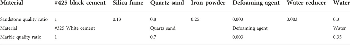
TABLE 1. Material ratios used for preparation of composite rock samples.
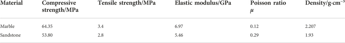
TABLE 2. Physical and mechanical parameters of two considered materials.
During the test, according to the test methodology set by the International Society of Rock Mechanics, we used a rectangular mold (143 × 70 × 70 mm; Figure 1A) to customize steel sheet 1 with the dimensions of 100 × 70 × 1 mm. We used 100 mm × L (fracture length) × 0.5 mm to customize steel sheet 2, both of which were inserted into the mold for pouring. We removed steel sheet 1 from a vibration table after 30 s of vibration, as shown in Figure 1B. The layered surface had improved bondage after 15 s of vibration. We let the plastic cover film stand for 10 h, and we removed steel sheet 2 to form the prefabricated fractures. After standing for 14 h, we removed the mold, which we placed in a standard curing room for 28 d to complete the preparation process. The final sample size was 143 × 70 × 70 mm, and the length of rock bridge b was 15 mm. The geometric configuration distribution of the sample with fractures is shown in Figure 2.
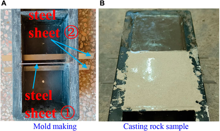
FIGURE 1. Process of preparing coplanar fracture composite rock sample. (A) Mold making, (B) Casting rock sample.
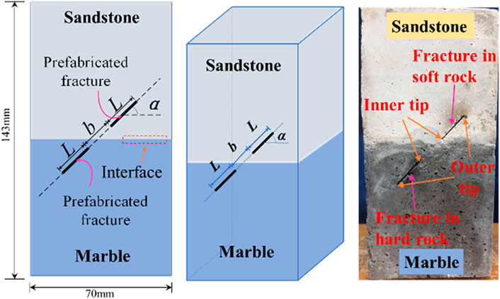
FIGURE 2. Configuration of fracture distribution.
The test system shown in Figure 3A included a loading module and DIC module. Figure 3B shows the photographic instrument used; the test method comprised uniaxial compression and a DIC test system.
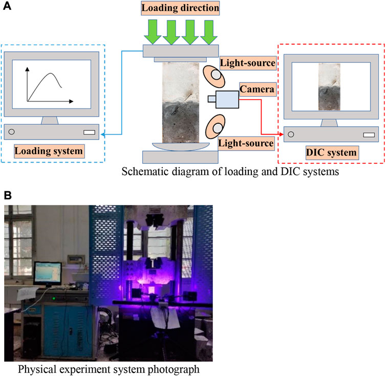
FIGURE 3. Schematic of testing system. (A) Schematic diagram of loading and DIC systems. (B) Physical experiment system photograph.
The loading system comprised a 100TWAW microcomputer-controlled electro-hydraulic servo universal testing machine, with a maximum load of 1,000 kN. The system not only controlled the force or displacement of the sample but also conducted uniaxial compression, tensile, cyclic loading, and creep tests. For the test, we adopted displacement control, and the displacement loading rate was 0.2 mm/min.
The DIC system comprised a noncontact, optical, three-dimensional measurement equipment for material displacement and strain measurement and analysis. The system primarily comprised a computer control system (DIC software and control box), support system (tripod, platform, and beam), and measurement system (camera and light source). We used double cameras at both ends of the beam for monitoring. The resolution, frame rate, lens focal length, light source focal length, and pixel size were 4096 × 3000 px, 30 fps, 12 mm, 10 mm, and 3.45 μm, respectively.
We conducted uniaxial compression tests using a 100TWAW microcomputer-controlled, electro-hydraulic servo universal testing machine. We used a DIC system to monitor the entire process of rock surface crack evolution. We used the inclination angle (α) and length (L) of the fracture as variables to investigate their influence on crack propagation and failure within the rock sample. The considered fracture inclination angles (α) were 0°, 30°, 45°, 60°, and 90°, and the fracture length (L) values were 6, 12, 18, and 24 mm. We designated the rock sample number according to the L–α format. Table 3 presents the test schemes and sample number.
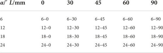
TABLE 3. Test scheme and sample number.
Figure 4 shows the stress–strain curve of the three intact rock samples. The peak strength of the composite rock (56.2 MPa) was between those of sandstone (53.8 MPa) and marble (64.4 MPa) and was closer to that of sandstone.
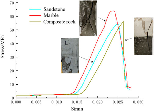
FIGURE 4. Stress–strain curves of three intact rock samples.
Figure 5 shows the law of the variation in the peak stress of the composite rock sample with respect to the fracture inclination angle and length. As shown in Figure 5A, when the fracture length was constant, the peak stress of the rock sample increased with an increase in the fracture inclination angle. When α = 90°, the peak stress of the rock sample was close to that of the complete composite rock sample. As shown in Figure 5B, when α ≠ 90°, the peak stress substantially decreased with the increase in fracture length, particularly when the fracture inclination angle was low; that is, when α ≤ 30°, the peak stress of the 24 mm sample decreased to 50% of that of the 6 mm sample. Furthermore, when α > 45°, the difference in the peak stress values of samples with different fracture lengths decreased; at α = 90°, the peak stress values of specimens with different fracture lengths were similar. Comparing the influence of the fracture inclination angle and length on peak stress, we found that the fracture inclination angle increased the range of peak stress, and the fracture inclination angle had a strong influence on rock strength.
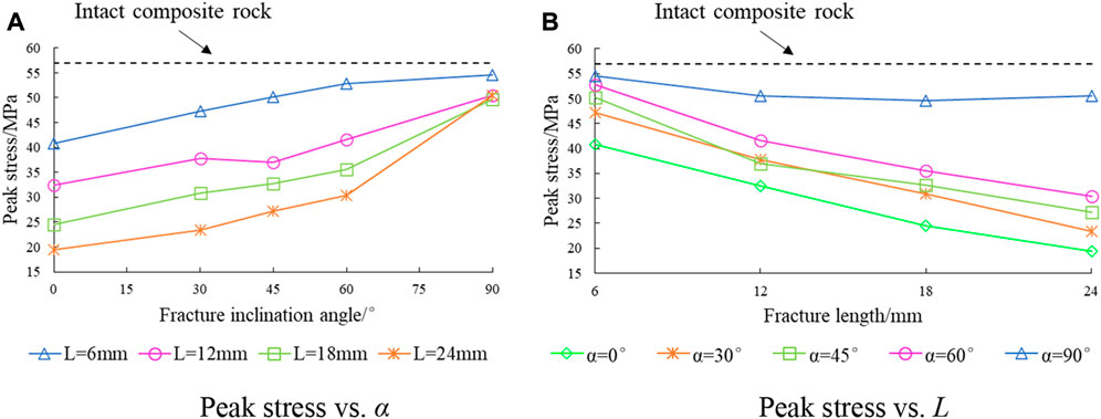
FIGURE 5. Variation in peak stress with fracture inclination angle and length. (A) Peak stress vs. α. (B) Peak stress vs. L.
To analyze the influence of geometric fracture characteristics on the strength of the composite rock samples, we used the degradation coefficient k, which can be defined as follows:
where σi and σ0 are the peak stress values of the fractured and intact composite rock samples, respectively; k is the degree of rock deterioration. The larger the k, the greater the rock sample deterioration and the lower the peak stress of the fractured composite rock sample, and vice versa. We determined the relationship between the fracture inclination angle and length and the deterioration coefficient, and the results are shown in Figure 6.
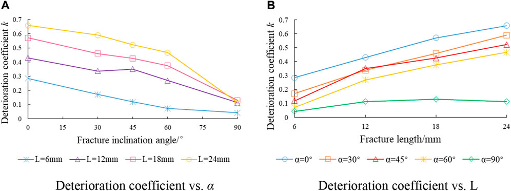
FIGURE 6. Relationship of deterioration coefficient with fracture inclination angle and length. (A) Deterioration coefficient vs. α. (B) Deterioration coefficient vs. L.
Figure 6A shows that the degradation coefficient decreased with an increase in the fracture inclination angle. When α = 90°, the degradation coefficient was stable, indicating that the increase in fracture inclination angle had an optimization effect on the strength of the rock samples. Additionally, when α ≤ 60°, the degradation coefficient slowly decreased with an increase in fracture inclination angle and remarkably decreased when α was close to 90°.
Figure 6B shows that at α ≤ 60°, the degradation coefficient slowly increased with the increase in fracture length, indicating that the increase in fracture length deteriorated the strength of the rock samples. When α = 90°, the degradation coefficient was hardly affected by the fracture length, and its values tended to fall between 0 and 0.1. Comparing the influence of the fracture inclination angle and length on the degradation coefficient, we found that the fracture inclination angle increased the range of the degradation coefficient and had a stronger influence on the rock strength. The failure types and mechanical properties of the rock samples became more complex under the joint action of the effects and deterioration caused by fracture inclination angle and fracture length. Therefore, the influence of geometric fracture characteristics on the mechanical properties of rock samples needs to be considered in actual engineering applications.
Figure 7 shows the law of variations in the elastic modulus with the changes in fracture inclination angle and fracture length. Figure 7A shows that 1) with an increase in the fracture inclination angle, the elastic modulus first slowly increased, then more rapidly increased, and finally slowed again; 2) when the fractured rock samples had both a low and high fracture inclination angle (α < 30°; α > 60°), the magnitude of the change in the elastic modulus was small: the range of the elastic modulus was the largest only when the fracture inclination angle was moderate (30 ≤ α ≤ 60°). Figure 7B shows that the elastic modulus decreased with increasing fracture length, the change range was small, and the maximum value was only 1.51 GPa (when L = 12 mm). Compared with the influence of the fracture inclination angle on the elastic modulus, the fracture inclination angle had a stronger influence on the elastic modulus and thus the rock deformation.
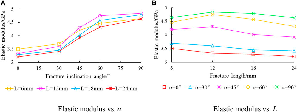
FIGURE 7. Relationship of elasticity modulus with fracture inclination angle and length. (A) Elastic modulus vs. α. (B) Elastic modulus vs. L.
Figure 8 shows the final failure modes of the composite rock samples with different fracture inclination angles and lengths. We used different colored lines in the figure to distinguish different types of cracks, namely red coarse lines for the prefabricated fractures, yellow lines for the cracks propagating from the prefabricated fracture tip to the principal stress direction, orange lines for the cracks at a certain distance from the tip of the prefabricated fracture and propagating in the direction of the principal stress, and blue lines for the cracks propagating from the end of the rock sample and locally existing cracks.
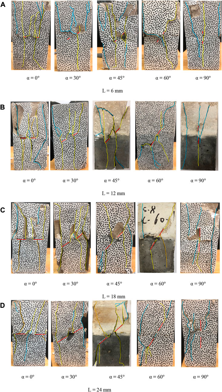
FIGURE 8. Final failure modes of composite rock samples with different fracture angles and lengths (A) L = 6 mm (B) L = 12 mm (C) L = 18 mm (D) L = 24 mm.
When the fracture inclination angles of the rock samples were the same, the final failure types of the rock samples were similar. The main difference was reflected in the intersection of the cracks in the rock bridge area. From the mechanics viewpoint, a change in the fracture inclination angle changes the break angle of rock samples and ultimately changes the failure mode of rock samples. When α = 0°, the wing crack at the inner and outer tips of the prefabricated fracture and the cracks generated in the middle of the prefabricated fracture expanded and penetrated in the principal stress direction, causing the rock sample to fail. When 30° ≤ α ≤ 60°, the failure of the rock samples was primarily caused by the propagation of wing cracks at the outer tip of the prefabricated fracture in the principal stress direction. The wing cracks at the inner tip of the prefabricated fractures penetrated the rock bridge or had a tendency to penetrate the rock bridge. When α = 90°, the tensile cracks at the end of the rock sample and the local cracks near the prefabricated fractures penetrated the rock sample, causing failure, which was similar to that of the complete composite rock.
The longer the fracture length, the fewer the macroscopic cracks generated, the higher the failure integrity of the rock sample, the lower the crack density in the rock bridge area, and the more difficult it is for the rock bridge to penetrate. These phenomena are the result of the influence of the fracture length on the compressive strength of the specimen, which also indicates that the failure mode of the specimen is the result of the joint action of the fracture inclination angle and rock strength.
When a fracture is present in sandstone, cracks more easily propagate, which break the sandstone apart. However, in cases where a facture develops in marble, the crack initiation stress is higher, and the crack propagates more quickly, resulting in more cracks in the sandstone section but only a few to no cracks in the marble section.
In summary, the geometric size of the fracture and the rock material properties change the failure mode of composite rock. The failure of the sample composite rock containing two coplanar fracture was primarily caused by wing or antiwing cracks at the tips of the two prefabricated fractures expanding in the direction of the principal stress, coalescing until they penetrated.
We summarize the failure characteristics of each rock sample in Figure 8 and Table 4. From the perspective of the microscopic failure mechanism, 1) when the fracture inclination angle was low (α = 0° or 30°), the cracks on the surface of the rock sample primarily comprised tensile cracks and we observed only few shear cracks, which were tensile failures, and double-Y-type failures (yellow lines in Figure 8A), where two main rupture cracks formed on its surface. 2) When α = 45° and 60°, the cracks generated on the surface were mixed shear and tension cracks , showing mixed tensile–shear failure. As the fracture length increased, the proportion of tension cracks also increased. When α = 45°, the surface of the rock sample formed a double-Z-type failure (yellow and orange lines in Figure 8D); when α = 60°, a main rupture Z-type crack failure (yellow lines in Figure 8C) formed on the surface of the rock sample. 3) When α = 90°, the cracks on the rock surface comprised mixed shear and tensile cracks, and the proportion of tensile cracks was large.
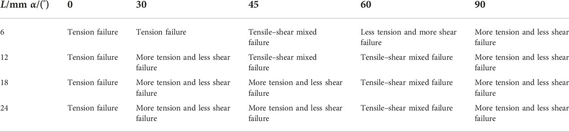
TABLE 4. Failure characteristics and composite rock samples.
In summary, compared with the influence of a single fracture or fracture in a single rock type (Fu et al., 2013; Miao et al., 2018; Wang et al., 2019), the influences of the fracture inclination angle of two fractures or composite rock on the mechanical properties of rock samples are similar. For example, as the fracture inclination angle increased, the peak strength and elastic modulus of the rock sample tend to increase; however, we observed substantial differences in crack propagation and failure mode. In the case of identical single fracture lengths, the fracture length of the double-fractured rock sample was longer than that of the single-fractured rock sample, which indicated that the proportion of defects was larger. Moreover, we found that the outer tips of the two fractures were closer to the end of the specimen; tensile cracks more easily formed when the crack expanded to the end of the sample. The coalescence of the rock bridge affected the failure mode of the sample, whereas the failure mode was not affected in the single-fractured rock sample.
Natural fractures are connected and penetrate each other, which leads to instability in rock mass structure and accidents. Therefore, the coalescence and penetration mechanisms of fractures must be studied. To further analyze the coalescence mode of coplanar fracture composite rock bridges, we defined four types of rock bridge coalescence: type I (no coalescence), type II (indirect coalescence), type III (coalescence trend), and type IV (direct coalescence). According to the four types of rock bridge coalescence, we classified the coplanar fractured composite rocks, as presented in Table 5.
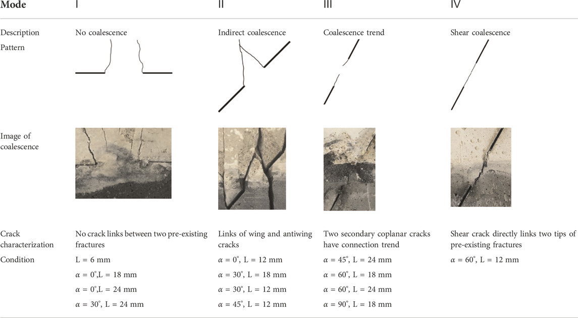
TABLE 5. Four typical modes of rock bridge coalescence in composite rock with coplanar fracture.
As shown in Table 5, type I coalescence primarily occurred in rock samples when α = 0° and L = 6 mm. When α = 0°, the direction of principal stress was perpendicular to the fracture, so the crack at the inner tip of the fracture extended in a direction perpendicular to the rock bridge. Thus, the rock bridge could not coalesce. When L = 6 mm, the fracture was too small, the length of the rock bridge was longer than that of the fracture, and the wing cracks at the inner tips of the fractures were far apart and could not penetrate. Type II coalescence primarily occurred when α = 30°, and types III and IV coalescence primarily appeared when α = 60°. We attributed the generation of type III coalescence to the inhibitory effect of the structural surface on the cracks. In many single-material rock samples with coplanar cracks (Yang, 2011; Huang and Yang, 2019), their rock bridges coalesce; thus, for composite rock, the difference between the two materials affects the coalescence of the rock bridge, thereby affecting the final failure mode. In conclusion, when L > 6 mm, the coalescence of the rock bridge was controlled by the fracture inclination angle. The larger the fracture inclination angle, the more easily the rock bridge coalesced. When α increased to 90°, the rock bridge no longer coalesced.
In the process of rock mass deformation and failure , cracks undergo four stages of expansion: compaction, initiation, expansion, and coalescence (Gao et al., 2016). Each stage corresponds to a specific stress threshold; that is, the characteristic stresses related to crack initiation, propagation, and coalescence include initiation, damage, and peak stresses. To analyze the law of the evolution of cracks at different stages, based on the three stress thresholds, we selected the time corresponding to the four characteristic stress points to analyze the law of the evolution of cracks in rock samples, namely initiation (σci), elastic (σce), peak (σpeak), and failure (σcf) stress, as shown in Figure 9.
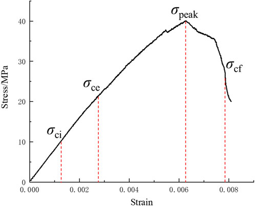
FIGURE 9. Four stress moments during compression.
We tracked and photographed the process of crack propagation of the rock samples at four moments using DIC, and we observed and analyzed the sequence of crack propagation With DIC, we captured photos, with number 6–0 as an example, and we more intuitively analyzed the law of crack propagation by sketching, as shown in Figure 10.
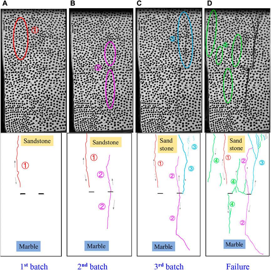
FIGURE 10. Propagation and distribution of surface cracks on specimen. ①, ②, ③, and ④represent the crack batches, and the arrow represents the direction of crack propagation. (A) 1st batch, (B) 2nd batch, (C) 3rd batch, (D) Failure.
The law of crack propagation on the surface of the rock samples was as follows: 1) At a low stress level, as shown in Figure 10A, the first batch of cracks appeared in the sandstone part and propagated in the principal stress direction. This batch of cracks were far-field cracks, which were primarily due to the uneven upper and lower ends of the rock sample or the uneven force on the end face. 2) At medium stress levels, cracks began to appear in the middle and tip of the prefabricated fractures and propagated in the direction of the principal stress, as shown in the second and third batches of cracks (Figures 10B,C). 3) At a high stress level, as shown in Figure 10D, cracks appeared at the tips of both prefabricated fractures, which rapidly propagated in the direction of the principal stress, and fused with other batches of cracks, forming main failure cracks and spalling blocks. At this time, the stress suddenly dropped, and the rock samples were destroyed.
For each batch of cracks marked in the failure diagram of the rock samples in Figure, we found that in the compaction stage at a low stress level, the stress required for crack initiation in the rock sample was not reached due to the low stress. Due to human error, the end of the rock sample could not be completely flat or smooth, resulting in the end effect, so that the first batch of cracks primarily generated from the end of the rock sample. With an increase in stress, the second batch of cracks appeared in the elastic stage, whereas the third and fourth batches of cracks appeared in the yield and after-the-peak stage, respectively. The dynamic change in the failure characteristics of the rock sample not only explained the law of crack propagation with the increase in stress but also revealed the failure characteristics of the rock sample. Therefore, we used a diagram of the failure characteristics to discuss the law of the change in the failure characteristics of the rock samples for different inclination angles and fracture lengths at different times. Figure 11 depicts the results.
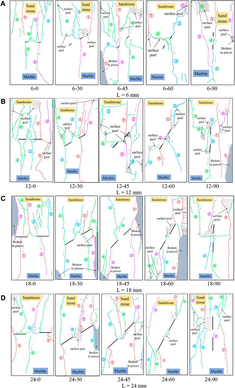
FIGURE 11. Variation in failure characteristics of rock samples with fracture angle under different fracture lengths. 6-0, 6-30, 6-45, 6-60, 6-90 (A) L = 6 mm. 12-0, 12-30, 12-45, 12-60, 12-90 (B) L = 12 mm. 18-0, 18-30, 18-45, 18-60, 18-90 (C) L = 18 mm. 24-0, 24-30, 24-45, 24-60, 24-90 (D) L = 24 mm.
Figure 11 shows that when α ≠ 90°, the positions of the four batches of cracks generated on the rock sample surface were primarily affected by the fracture length. This was due to the following reasons: 1) when L ≤ 12 mm, the first and second batch cracks primarily appeared in the right half of the rock sample, whereas the third and fourth batches of cracks primarily appeared in the left half. When L > 12 mm, this phenomenon weakened, and different batches of cracks uniformly covered the rock sample surface. 2) With the increase in fracture length, the evolution of the first batch of cracks was as follows: generated from the end of the rock sample → generated from the tip of the prefabricated fracture in sandstone → generated from the tips of the two prefabricated fractures. The evolution of the second batch of cracks was as follows: generated from the tip of the prefabricated fracture in sandstone → generated from the tips of the two prefabricated fractures → generated from the end of the rock sample. Because the crack initiation stress in sandstone was lower than that in marble, the cracks in the early batches were initially generated from the tip of the prefabricated fractures in sandstone. 3) With the increase in fracture length, the crack initiation stress of the composite rock decreased. Simultaneously, the stress of the prefabricated fracture in the sandstone and marble required to initiate a crack initiation is also continuously reduced to a state with a small difference, and therefore, the crack initiation stresses of sandstone and marble were close. Consequently, the cracks uniformly appeared on the rock sample surface. When α = 90°, the locations of cracks in the same batch were also similar. The first and second batches of cracks were primarily generated from the end of the rock sample and extended in the principal stress direction. The third batch of cracks was primarily generated near the prefabricated fractures, and the fourth batch of cracks primarily comprised far-field cracks.
Particle Flow Code 2D (PFC2D) software is typically used to simulate the mechanical properties of rocks. In this study, we used PFC2D to conduct uniaxial compression tests on the composite rock samples with coplanar fractures to explore the failure modes and crack propagation processes at different fracture inclination angles and lengths. We introduced a discrete element fracture network to represent the soft–hard layers, and we replaced the flat joint contact model intersecting the fracture network with the smooth joint contact model. Figure 12 shows the generated model, and Table 6 presents the bond parameters of the particles.
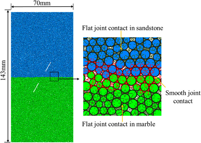
FIGURE 12. Schematic diagram of composite rock model with coplanar double fractures.
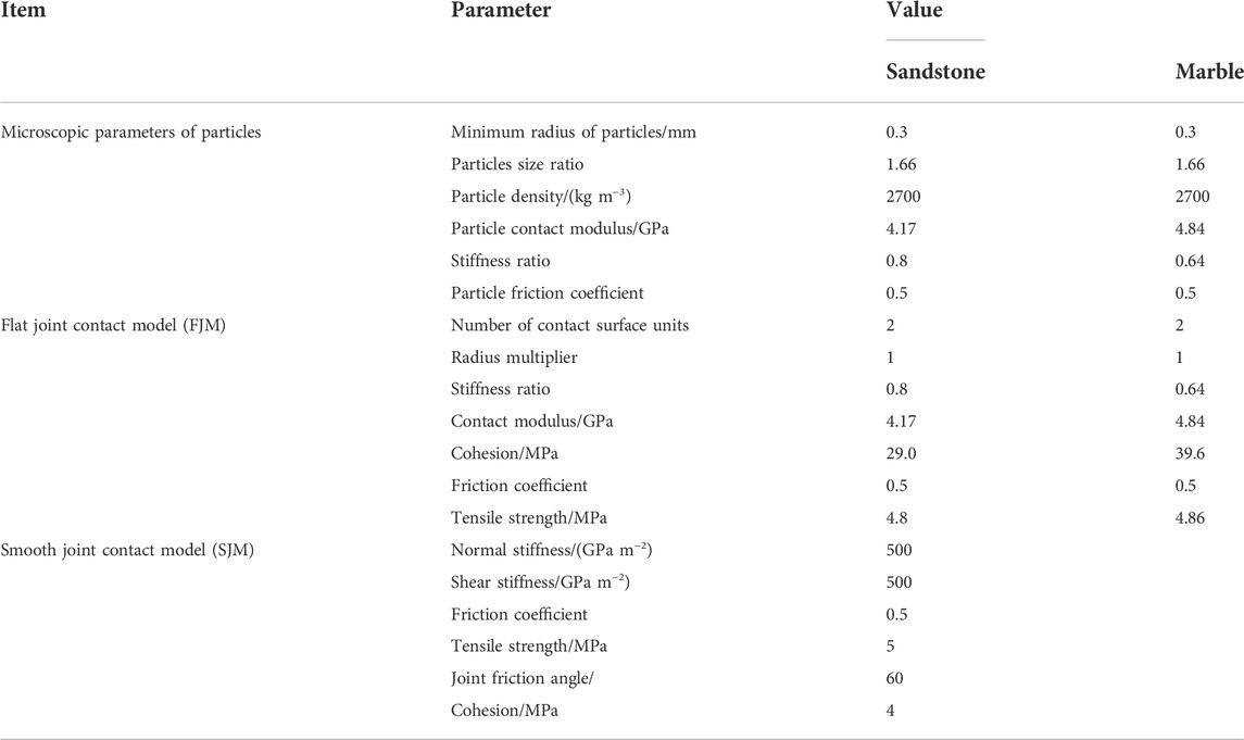
TABLE 6. Microscopic parameters of PFC2D model.
Because the particles in PFC2D undergo initial compaction after generation, the simulated stress–strain curve has no compaction stage. To facilitate comparison, we shifted the simulated curve to the right by an appropriate unit to obtain the stress–strain curves of intact sandstone, marble, and composite rock. Figure 13 shows the curves, which reveal that the simulated uniaxial compressive strength, peak strain, elastic modulus, and failure results were similar to those obtained in the laboratory tests. We used PFC2D to simulate the microcrack propagation of the rock samples with different fracture inclination angles and lengths at three specific stress thresholds, σci, σcd, and σpeak, to explore the influence of the fracture inclination angle and length on the propagation of cracks in the composite rock samples. Figure 14 shows the microcrack propagation in rock samples for α = 0°, 30°, and 60° and at L = 12 mm. Figure 15 shows the microcrack propagation in rock samples with L = 18 and 24 mm and at α = 30°.
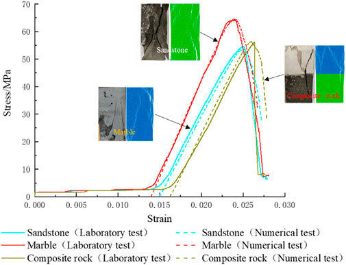
FIGURE 13. Stress–strain curves of sandstone, marble, and composite rocks.
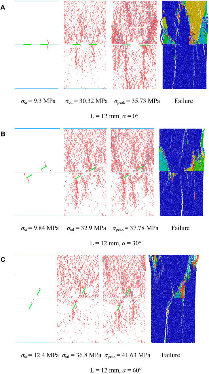
FIGURE 14. Microcrack propagation process of rock samples at different fracture inclination angles when L = 12 mm. (A) L = 12 mm, α = 0°, (B) L = 12 mm, α = 30°, (C) L = 12 mm, α = 60°.
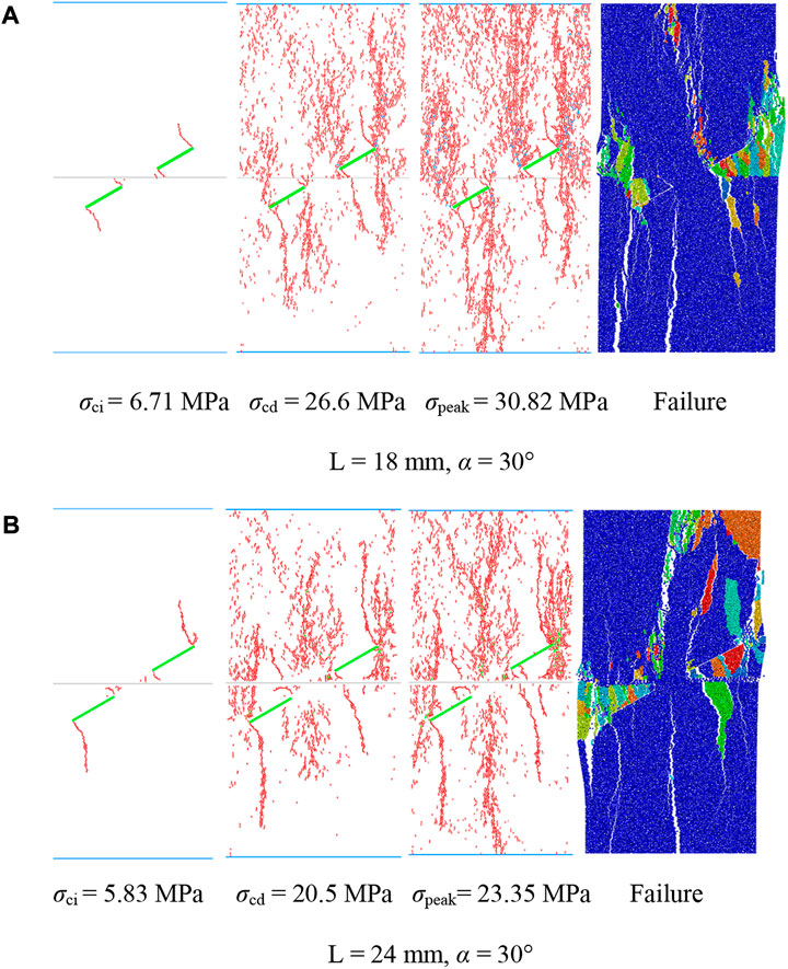
FIGURE 15. Microcrack propagation process of rock samples at different fracture lengths when α = 30° (A) L= 18 mm, α = 30°, (B) L= 24 mm, α = 30°.
Figure 14 shows that 1) when the inclination angle of the prefabricated fracture was small (α ≤ 30°), the cracks aggregated in a band in the sample after compression, and a dense crack aggregation band appeared near the prefabricated fracture. This finding explained why the prefabricated fracture tip of the rock samples was relatively broken at the macro level. This also indicated that the prefabricated fracture tip produced an area of stress concentration, which was also the area where cracks preferentially initiated and propagated. 2) When the fracture inclination angle increased gradually from 0°, the aggregation band of this type of crack gradually weakened, owing to the change in the particle motion path caused by the change in the fracture inclination angle. The specific process was as follows: when α ≤ 30°, the crack distribution under the corresponding damage stress was similar, primarily manifesting as crack aggregation at the crack tip. When α > 30°, as shown in Figure 14C, cracks filled the entire sample surface, where the lower the degree of crack aggregation, the higher the damage stress. 3) As the inclination angle of the fracture increased, the stress at the three stages also gradually increased, indicating that the strength of the sample gradually increased when it expanded in the dispersive direction. 4) The sandstone experienced many more microcracks than the marble. From a microscopic viewpoint, we determined the reason sandstone was more broken and marble was relatively complete. 5) During the loading of the composite rock, the microcracks initially expanded from the prefabricated fracture tip in the direction of principal stress; however, when α > 0°, the microcracks more easily developed at the outer tip of the prefabricated fracture, while the crack at the inner tip slowly developed or did not develop because of the influence of the strata interface.
Figures 14B, 15 show that for the same fracture inclination angle, with the increase in fracture length, the cracks showed a band of aggregation in the samples, the number of cracks considerably reduced, and crack propagation did not occur in numerous blank areas. However, owing to the increase in the fracture length, the three specific stress threshold points, σci, σcd, and σpeak, during the expansion process of the specimen decreased. From a microscopic viewpoint, we found that with the increase in fracture length, the crack propagation diagrams corresponding to the initiation and damage stress of the rock samples were similar, indicating that the time required for crack propagation gradually decreased, the specimen was more rapidly destroyed, and the crack at the prefabricated fracture tip more easily passed through the interface of the rock stratum. Crack propagation primarily occurred when the crack at the tip of the prefabricated fracture first extended to both ends, to a certain extent, and then extended along the left and right ends of the entire sample away from the fracture. We observed that a macroscopic crack formed when the crack propagation gathered to a certain extent. During the real-time monitoring of the propagation of microcracks through PFC, we found that the sequence of the occurrence of most initial cracks in the composite rocks was also regular, and the cracks were blocked by the rock strata interface. We use the rock samples with L = 12 mm and α = 30° as examples in Table 7.
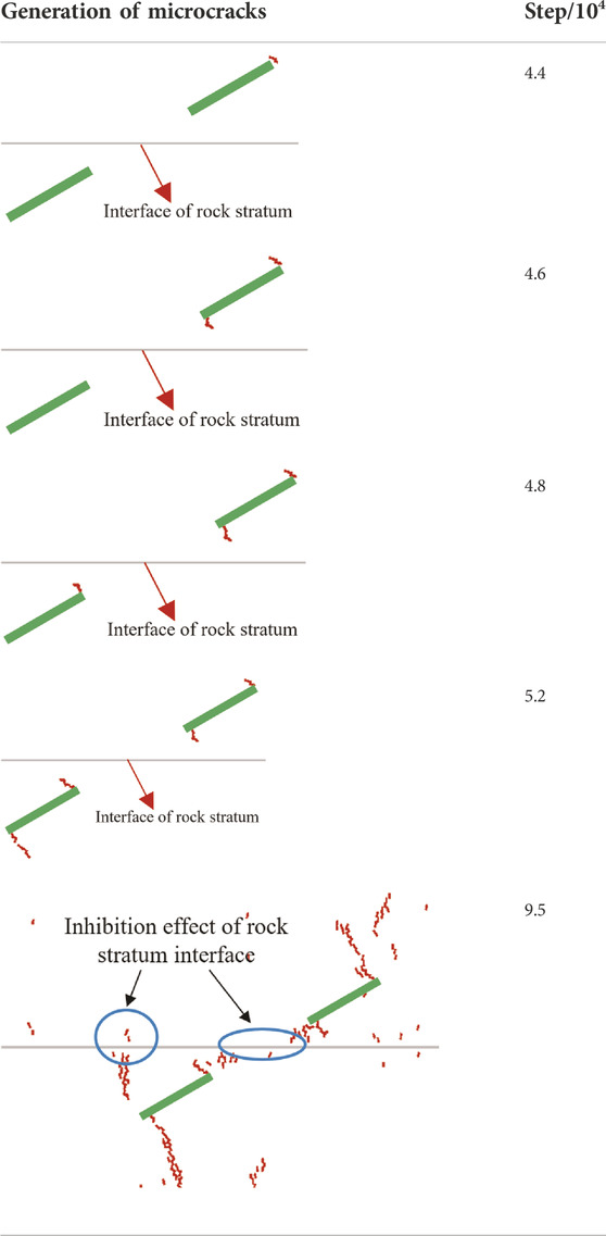
TABLE 7. Schematic of initial microcrack generation.
Table 7 shows that 1) the sequence of the generation of initial microcracks over time was as follows: the outer tip of the sandstone prefabricated fracture → the inner tip of the sandstone prefabricated fracture → the inner tip of the marble prefabricated fracture → the outer tip of the marble prefabricated fracture. That is, cracks generated from the right end of the rock sample to the left end. Owing to the short interval between occurrences, two microcracks simultaneously occurred, which we additionally observed from a microscopic point of view, to verify the macrocrack law. 2) As the loading progressed, the crack at the tip of the prefabricated fracture in the marble was blocked by the interface of the rock layer when it expanded in the direction of the sandstone, which was the same as what occurred when the macrocrack expanded, indicating that the microcracks and macrocracks were interconnected. The aggregation of microcracks created macrocracks, which were also affected by the rock interface.
In conclusion, the existence of a material interface in composite rock primarily inhibits the propagation of cracks both near the interface and toward another material. Therefore, the penetration ability of the rock bridge and the development ability of the wing crack at the tip of the prefabricated crack weaken, thus changing the failure mode of composite rock, and finally leading to the three types of failure. However, this inhibiting ability is limited and cannot block the propagation of all cracks; particularly when the inclination angle of the fracture is 0°, the inhibiting ability is minimized.
We drew the following conclusions:
(1) Mechanical properties of fractured composite rock: With an increase in the fracture inclination angle, the peak stress and elastic modulus of the rock samples showed an increasing trend, and the degradation coefficient showed a decreasing trend. As fracture length increased, the peak stress and elastic modulus of the rock samples showed decreasing trends, and the degradation coefficient showed an increasing trend. The fracture inclination angle more strongly influenced the mechanical properties than fracture length.
(2) Failure mode of the fractured composite rock: The failure type of the fractured composite rock was primarily affected by the inclination angle of the fracture. With an increase in the fracture inclination angle, the rock samples exhibited a change of: double-Y-type → double-Z-type → Z-type failures. The crack type changed from tensile to shear, produced mixed tension and shear failures.
(3) Rock bridge coalescence mode of fractured composite rock: The rock bridge coalescence was primarily affected by the fracture inclination angle and rock structural plane. When α < 90°, the larger the fracture inclination angle, the closer the rock bridge to coalescence. When α = 90°, the rock bridge no longer coalesced. The composite rock structural plane inhibited crack propagation, weakening the coalescence ability of the rock bridge
(4) Dynamic failure law of fractured composite rock: We defined the cracks generated at four time points, and we found that the position of the cracks was primarily affected by the length of the fracture. When L ≤ 12 mm, the first and second batches of cracks primarily appeared in the right half of the rock sample, and the third and fourth batches of cracks appeared primarily in the left half. When L > 12 mm, all batches of cracks (first to fourth) uniformly distributed on the surfaces of the rock samples.
(5) According to the PFC2D simulation results, when the fracture length was constant and α ≤ 30°, bands of crack aggregation formed after specimen expansion, and dense bands of crack aggregation all appeared near the prefabricated fracture. When α > 30°, with the increase in fracture inclination angle, the crack aggregation bands gradually weakened, and the cracks expanded in the direction of dispersion. With increasing fracture length, cracks became more aggregated, and the number of cracks decreased when the fracture inclination angle was constant. The structural plane also inhibited the propagation of microcracks.
The raw data supporting the conclusions of this article will be made available by the authors, without undue reservation.
Conceptualization: HY and TX; methodology: HY and TX; software: HY and XC; formal analysis: HY and HS; data curation: HY, TX, and HS; writing—original draft preparation: HY and TX; writing—review and editing: HY and TX; supervision: TX; project administration: TX and HS; funding acquisition: TX. All authors have read and agreed to the published version of the manuscript.
This study was supported by the Hubei Provincial Science and Technology Plan Project Foundation of China (grant no. 2020AC15), Shanxi Provincial Key Laboratory of Concrete Structure Safety and Durability Open Fund of China (grant no. SZ02105), and Open Fund for the State Key Laboratory of Geomechanics and Engineering of China (grant no. Z020013).
The authors declare that the research was conducted in the absence of any commercial or financial relationships that could be construed as a potential conflict of interest.
All claims expressed in this article are solely those of the authors and do not necessarily represent those of their affiliated organizations, or those of the publisher, the editors and the reviewers. Any product that may be evaluated in this article, or claim that may be made by its manufacturer, is not guaranteed or endorsed by the publisher.
Chen, Y., Cui, D., Bian, K., Li, Y., and Liang, W. (2020). Particle flow analysis on mechanical characteristics of composite rock samples containing coplanar double fractures. Saf. Environ. Eng. 27 (02), 140–148. doi:10.13578/j.cnki.issn.1671-1556.2020.02.019
Dong, J., Yang, S., Li, B., and Huang, Y. (2020). Experimental study on the tensile strength of rock-like materials containing two pre-existing coplanar fractures. Eng. Mech. 37 (03), 188–201. doi:10.6052/j.issn.1000-750.2019.04.0232
Fu, J., Yuan, Y., Zhao, Y., Li, S., and Yu, J. (2019). Microscopic simulation of damage failure characteristics of double fracture rock under uniaxial dynamic compression. J. Hunan Univ. Arts Sci. Nat. Sci. Ed. 31 (3), 57–63. doi:10.3969/j.issn.1672-6146.2019.03.011
Fu, J., Zhu, W., Cao, G., Xue, W., and Zhou, K. (2013). Experimental study and numerical simulation of propagation and coalescence process of a single three-dimensional flaw in rocks. J. China Coal Soc. 38 (3), 411–417. doi:10.13225/j.cnki.jccs.2013.03.003
Gao, M., Li, T., Meng, L., Chen, G., Chen, C., Liao, A., et al. (2016). The method to identify characteristic stresses of rock in different stages during failure process. Chin. J. Rock Mech. Eng. 35 (S2), 3577–3588. doi:10.13722/j.cnki.jrme.2015.1645
Huang, Y., and Yang, S. (2019). Mechanical and cracking behavior of granite containing two coplanar flaws under conventional triaxial compression. Int. J. Damage Mech. 28 (4), 590–610. doi:10.1177/1056789518780214
Huang, Y., Yang, S., and Zhao, J. (2016). Three-dimensional numerical simulation on triaxial failure mechanical behavior of rock-like specimen containing two unparallel fissures. Rock Mech. Rock Eng. 49 (12), 4711–4729. doi:10.1007/s00603-016-1081-2
Li, F., and Li, X. (2013). Micro-numerical simulation on mechanism of fracture coalescence between two pre-existing flaws arranged in echelon. J. Shenzhen Univ. Sci. Eng. 30 (2), 190–194. doi:10.3724/SP.J.1249.2013.02190
Li, X., Lu, Y., Kang, Yong, and Rao, B. (2007). Rock mechanics experiment simulation technology. Beijing: science press.
Li, X., Xiao, T., Wang, B., and Xu, P. (2012). Experimental study of jinping ii hydropower stationmarble under loading and unloading stress paths. Chin. J. Rock Mech. Eng. 31 (5), 882–889.
Liu, J., Wang, E., Song, D., Wang, S., and Niu, Y. (2015). Effect of rock strength on failure mode and mechanical behavior of composite samples. Arab. J. Geosci. 8 (7), 4527–4539. doi:10.1007/s12517-014-1574-9
Liu, Q., Shi, K., and Huang, X. (2013). Feasibility of application of TBM in construction of deep coal mine and its key scientific problems. J. Min. Saf. Eng. 30 (05), 633–641.
Lu, Y., Li, X., and Wu, X. (2014). Fracture coalescence mechanism of single flaw rock specimen due to freeze-thaw under triaxial compression. Rock Soil Mech. 35 (6), 1579–1584. doi:10.16285/j.rsm.2014.06.009
Miao, S., Pan, P., Wu, Z., Li, S., and Zhao, S. (2018). Fracture analysis of sandstone with a single filled flaw under uniaxial compression. Eng. Fract. Mech. 204, 319–343. doi:10.1016/j.engfracmech.2018.10.009
Rad, H., and Ayassaghi, (2004). Squeezing rock conditions at an igneous contact zone in the taloun tunnels, tehran-shomal freeway, Iran: A case study. Int. J. Rock Mech. Min. Sci. 42 (1), 95–108. doi:10.1016/j.ijrmms.2004.07.002
Sun, K., Xu, W., Qiu, W., Li, H., Xian, Q., and Li, T. (2018). Study on the characteristics of safety distribution changing with buried depth for metro station in upper-soft and lower-hard stratum. Adv. Civ. Eng., 2018. 1–14. doi:10.1155/2018/6047919
Tang, Y., and Xu, J. (2016). Shield tunneling in rock–soil interface composite formations. Geotech. Geol. Eng. (Dordr). 34 (6), 1693–1705. doi:10.1007/s10706-016-9994-9
Tian, W., Yang, S., and Huang, Y. (2017). PFC2D simulation on crack evolution behavior of brittle sandstone containing two coplanar fractures under different confining pressures. J. Min. Saf. Eng. 34 (06), 1207–1215. doi:10.13545/j.cnki.jmse.2017.06.026
Tu, H., Zhou, H., Qiao, C., and Gao, Y. (2020). Excavation and kinematic analysis of a shallow large-span tunnel in an up-soft/low-hard rock stratum. Tunn. Undergr. Space Technol. 97, 103245. doi:10.1016/j.tust.2019.103245
Wang, Q., Wang, J., Ye, Y., Wang, W., Huang, C., Hu, N., et al. (2020). Development and preliminary verification of the evaluation system for clinical practice guidelines in China. Chronic Dis. Transl. Med. 2, 134–139. doi:10.1016/j.cdtm.2019.08.007
Wang, W., Zhang, X., Hu, M., and Zhang, H. (2019). Conversion timing of tunnel excavation methods in upper-soft and lower-hard stratum based on displacement direction angle theory: Case study. Int. J. Geomech. 19 (4), 05019003. doi:10.1061/(ASCE)GM.1943-5622.0001380
Wang, Z., Zhao, W., and Pan, K. (2020). Analysis of fracture evolution characteristics of coplanar double fracture rock under uniaxial compression. Geotech. Geol. Eng. (Dordr). 38 (1), 343–352. doi:10.1007/s10706-019-01022-9
Wu, B., Lan, Y., Huang, W., and Yang, S. (2019). Study on vibration of tunnel blasting construction in upper soft and lower hard ground IOP conference series: Earth. IOP Conf. Ser. Earth Environ. Sci.IOP Publ. 242 (6), 062004. doi:10.1088/1755-1315/242/6/062004
Xi, X., Wu, X., Guo, Q., and Cai, M. (2020). Experimental investigation and numerical simulation on the crack initiation and propagation of rock with pre-existing cracks. IEEE Access 8, 129636–129644. doi:10.1109/ACCESS.2020.3009230
Xiao, T., Li, X., and Guo, Y. (2012a). Experimental study of failure characteristic of single jointed rock mass under triaxial compression. Rock Soil Mech. 178, 28–48. doi:10.16285/j.rsm.2012.11.008
Xiao, T., Li, X., and Jia, S. (2012b). Triaxial test research and mechanical analysis based onstructure surface effect of deep rock mass withsingle fracture. Chin. J. Rock Mech. Eng. 31 (8), 1666–1673.
Yan, J., Hu, X., and Liu, B. (2020). Stability of shield tunnel excavation face in upper-soft and lower-hard composite strata. Tunn. Constr. 40 (02), 223–230.
Yang, Q., and Liu, Y. (2012). Simulations of crack propagation in rock-like materials using particle flow code. Chin. J. Rock Mech. Eng. 31 (S1), 3123–3129.
Yang, S., Chen, M., Fang, G., Wang, Y., Meng, B., Li, Y., et al. (2018). Physical experiment and numerical modelling of tunnel excavation in slanted upper-soft and lower-hard strata. Tunn. Undergr. Space Technol. 82, 248–264. doi:10.1016/j.tust.2018.08.049
Yang, S. (2011). Crack coalescence behavior of brittle sandstone samples containing two coplanar fissures in the process of deformation failure. Eng. Fract. Mech. 78 (17), 3059–3081. doi:10.1016/j.engfracmech.2011.09.002
Yang, S., Huang, Y., Jing, H., and Liu, X. (2014). Discrete element modeling on fracture coalescence behavior of red sandstone containing two unparallel fissures under uniaxial compression. Eng. Geol. 178, 28–48. doi:10.1016/j.enggeo.2014.06.005
Yin, P., Yang, S., and Zeng, W. (2015). Simulation of strength and crack propagation characteristics of composite rock strata with single fracture. J. Basic Sci. Eng. 23 (03), 608–621. doi:10.16058/j.issn.1005-0930.2015.03.019
Zhang, H., Wan, Z., Zhang, Y., and Wu, D. (2018). Mechanical properties and failure behavior of composite samples. Adv. Mater. Sci. Eng., 2018. 1–16. doi:10.1155/2018/2545127
Zhang, J., and Zhou, X. (2020). AE event rate characteristics of flawed granite: From damage stress to ultimate failure. Geophys. J. Int. 222 (2), 795–814. doi:10.1093/gji/ggaa207
Zhang, L., Jing, H., Ding, S., and Yang, L. (2017). Discrete element study on crack coalescence behavior of sandstone with two parallel fractures. Coal Technol. 36 (4), 326–329. doi:10.13301/j.cnki.ct.2017.04.120
Zhang, Y., Wang, K., Yao, X., Liang, P., and Liu, X. (2019). Simulation experiment study on the effect of fracture geometry on rock strength. China Min. Mag. 28 (08), 141–148.
Zhou, X., Cheng, H., and Feng, Y. (2014). An experimental study of crack coalescence behaviour in rock-like materials containing multiple flaws under uniaxial compression. Rock Mech. Rock Eng. 47 (6), 1961–1986. doi:10.1007/s00603-013-0511-7
Zhou, X., Lian, Y., Wong, L. N. Y., and Berto, F. (2018). Understanding the fracture behavior of brittle and ductile multi-flawed rocks by uniaxial loading by digital image correlation. Eng. Fract. Mech. 199, 438–460. doi:10.1016/j.engfracmech.2018.06.007
Zhou, X., Wang, Y., Zhang, J., and Liu, F. (2019). Fracturing behavior study of three-flawed specimens by uniaxial compression and 3D digital image correlation: Sensitivity to brittleness. Rock Mech. Rock Eng. 52 (3), 691–718. doi:10.1007/s00603-018-1600-4
Zhou, X., and Zhang, J. (2021). Damage progression and acoustic emission in brittle failure of granite and sandstone. Int. J. Rock Mech. Min. Sci. 143, 104789. doi:10.1016/j.ijrmms.2021.104789
Keywords: coplanar fracture, composite rock, rock-like materials, mechanical properties, failure law, dynamic characteristic, PFC2D, crack propagation
Citation: Yuan H, Xiao T, She H, Zheng Y and Chen X (2023) Mechanical properties and failure law of composite rock containing two coplanar fractures. Front. Earth Sci. 10:1007439. doi: 10.3389/feart.2022.1007439
Received: 30 July 2022; Accepted: 20 September 2022;
Published: 06 January 2023.
Edited by:
Dongdong Yao, China University of Geosciences Wuhan, ChinaCopyright © 2023 Yuan, Xiao, She, Zheng and Chen. This is an open-access article distributed under the terms of the Creative Commons Attribution License (CC BY). The use, distribution or reproduction in other forums is permitted, provided the original author(s) and the copyright owner(s) are credited and that the original publication in this journal is cited, in accordance with accepted academic practice. No use, distribution or reproduction is permitted which does not comply with these terms.
*Correspondence: Taoli Xiao, MjAwNTM2QHlhbmd0emV1LmVkdS5jbg==; Haicheng She, c2hlaGFpY2hlbmdAMTI2LmNvbQ==
Disclaimer: All claims expressed in this article are solely those of the authors and do not necessarily represent those of their affiliated organizations, or those of the publisher, the editors and the reviewers. Any product that may be evaluated in this article or claim that may be made by its manufacturer is not guaranteed or endorsed by the publisher.
Research integrity at Frontiers
Learn more about the work of our research integrity team to safeguard the quality of each article we publish.