- 1School of Resources and Safety Engineering, Central South University, Changsha, China
- 2School of Geological and Mining Engineering, Xinjiang University, Urumqi, China
- 3China Nonferrous Metal Mining Group Co., Ltd., Beijing, China
This study aims to investigate the fracturing characteristics of double-hole blasting under the action of coupled static stress and delayed time explosion. A total of thirteen explosive tests were carried out on rectangular concrete blocks with different constraints. The test blocks were wrapped in steel mesh in the test bed to prevent flying away of the cracked blocks after blasting. After blasting, the surface area of the crater was measured, and all pieces of the cracked blocks were collected, screened, and analyzed. The experimental results show that (1) the shape of free-surface craters was affected by static stress. The surface area and overall volume of the craters increased in the direction of loading stress. (2) The crater under simultaneous initiation was larger than that under delayed initiation when the tested block had a single free surface. (3) The fragmentation of blasting is closely related to the static confining pressure and delay initiation applied on the tested specimens. It is believed that this research will contribute to the design of multi-hole blasting in the deep geological body in the respect of the theoretical analysis.
Introduction
The depletion of shallow resources and increasing demand for metal sources have led to increasing interest in underground mining, featured by high in situ stress in deep Earth (Fan et al., 2009). Drilling and blasting are always employed for these underground rock excavations due to their economic cost and effectiveness. However, under high in situ stress, the rock breaking produced by underground blasts differs from that generated from open-pit mining and shallow excavation (Yan et al., 2016; Han et al., 2020). To make the fragmentation law clear under the coupling action of high in situ stress and blasting, it is of great significance for determining blasting parameters and safe and efficient production in deep ore bodies. They carried out physical experiment research of double-hole blasting to determine the blasting parameters of deep rock mass that are necessary to realize safe and efficient excavation and mining (Yilmaz and Unlu, 2013; He et al., 2018; Jayasinghe et al., 2019). At present, scholars have carried out a lot of research work on rock breaking by blasting under in situ stress. Some theories and experiments have been carried out on rock blasting under high ground stress (Xiao et al., 1996).
Many research studies have been carried out on the mechanism of blasting fracture (Zhu et al., 2016). Static stress can reduce the fracture length and the area of the blasting damage zone. Moreover, the tensile strength of rock under the coupling action of static and dynamic loads decreases with the increase in the static prestress, indicating that high ground stress can enhance the fragmentation of rock under blasting excavation (Zhao et al., 2017). The aforementioned studies illustrated the influence of static stress on the blasting fracture of rock materials, and in situ stress played a key role in crack initiation and growth. Based on these studies, the influence of in situ stress on blasting rock fracture was analyzed and experimentally studied (Li et al., 2021; Wu et al., 2015; Zhang et al., 2017). The results show that the cracks caused by blasting stress wave and gas pressure grow well in the direction of the maximum principal stress of the superimposed stress field (Kutter and Fairhurst, 1971). It calculated the rock breakage caused by blasting under high stress based on fracture mechanics and rock damage criterion. The results showed that the release of strain energy in high-stress rock mass was beneficial to improve the crushing effect. Based on this, they studied the propagation characteristics of blasting crack in dynamic and static stress fields by the caustic experiment. The results showed that in situ stress had an important influence on the crack growth caused by blasting (Xiao et al., 2019). When the direction of vertical in situ stress was in the direction of crack propagation, the crack growth was restrained. It experimentally simulated the blasting failure characteristics of rock mass under different stress conditions, and the influence of the in situ stress value and direction on presplitting blasting was studied (Yang et al., 2019). The damage of the gypsum block decreased with the increase in uniaxial pressure. The article studied the influence law and the response of the main crack induced by blasting the initial static stress field using dynamic and static loading experimental equipment to simulate static stress field, and a digital laser dynamic caustic system was used to collect data (Yang et al., 2021). The findings revealed that the combined action field of the initial static stress and the dynamic blasting stress field gave priority to the maximum crack propagation along the initial static stress direction (Yang and Ding, 2018). The study simulated the blasting disturbance of the underground tunnel through a physical model test and analyzed the influence of the blasting position on surface deformation and failure characteristics (Qiu et al., 2021). The work studied the crater blasting under different confining pressures through theoretical analysis and physical model tests. Under the condition of the uniaxial load, the shape of the crater in the long axial loading direction was elliptical with the increase in the confining pressure, and the opening angle and pit volume in this direction increased (Peng et al., 2020; Zhang et al., 2021).
Some experiments and numerical simulation studies were carried out on rock blasting under high ground stress (Li et al., 2021; Jayasinghe et al., 2019). The research results show that the existence of high ground stress changed the propagation direction and propagation length of explosion-induced cracks. The cracks first radiated outward from the blast hole wall and then gradually extended outward along the direction of the maximum principal stress (He and Yang, 2019). The article used the RHT model in LS-DYNA to simulate the blasting damage characteristics of the high-stress rock mass. Under uniaxial loading, the crater volume increased with the increase in the confining pressure (Huo et al., 2021). The uniaxial static load could change the optimal load and the critical buried depth of charge. The granitic lithology with a complete deep structure has high energy storage capacity (Wang et al., 2019; Zhang et al., 2020). The influence of the confining pressure and ratio of horizontal pressure to vertical pressure on blasting rock fracture was studied through experiments. The results showed that the direction of crack propagation was mainly controlled by circumferential tensile stress and biaxial preload ratio (He and Yang, 2019).
The combined finite-discrete element method (FDEM) was used to simulate the excavation damage area of rock mass caused by contour blasting. It was found that blasting cracks initially spread along the horizontal direction of ground stress under high level of in situ stresses. The following study was carried out on the double-hole test. Increasing the millisecond initiation time between adjacent holes could form a better crack network between holes and make radial cracks penetrate through (Zhao et al., 2017). The research results showed that through the field test and numerical analysis it was found that the larger the distance between adjacent holes, the closer the main cracks to the connecting direction of holes (LEI and JIANG, 2019). The blasting of high-stress rock mass was studied using the coupled numerical simulation method of smooth particle hydrodynamics and finite element method. The crack propagation length between the blast holes decreased with the increase in the local stress level, and the crack mainly expanded parallel to the direction of maximum principal stress. Arranging the blast holes along the direction of maximum principal stress and shortening the distance between the blast holes were considered to be beneficial to the connection and penetration of cracks between the blast holes. The influence of the confining pressure and ratio of horizontal pressure to vertical pressure on blasting rock fracture was studied through experiments. The results showed that the direction of crack propagation was mainly controlled by circumferential tensile stress and biaxial preload ratio.
The aforementioned studies were mostly conducted in the numerical simulation experiments of single-hole blasting and double-hole blasting. It is thus critically urgent to conduct the physical model test to further explore the influence of static stress on rock breaking by double-hole blasting. In this study, the influence of static stress on the double-hole crater and fragmentation under the condition of a single free surface was studied by laboratory tests, the main contribution of which is to provide the theoretical foundation to the design of multi-hole blasting in the deep geological body.
Blasting Test of a Concrete Block Under the Static Stress
Test Block
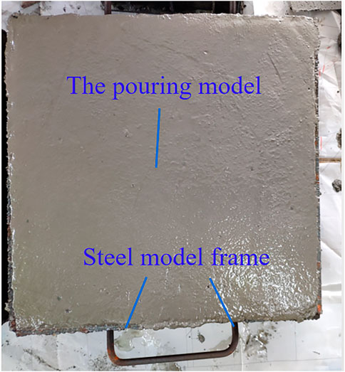
Cement blocks are widely used to simulate brittle rocks in blasting tests because cement mortar has the characteristics of homogeneity, isotropy, and designable strength. In this study, a series of blasting model tests were conducted using solid cement mortar and block stones. The test block was made of sand with uniform particle size, ordinary Portland cement (PC42.5), small stones, and water. Figures 1, 2 show the geometric dimensions of the model test block. The model test block adopted cuboid specification (Figure 1), and its size was 400 × 400 × 200 mm3. During the preparation of the test block, three groups of 120 × 120 × 120 mm3 cube test blocks were poured with the same mixture, and the physical and mechanical parameters of the test blocks were measured with the cube test blocks. Compressive strength and elastic modulus were measured using the CSS-YAW3000 electrohydraulic servo pressure frame and the KD7016A static strain test and analysis system. A CTS-25 nonmetal ultrasonic detector was used to measure the longitudinal wave velocity of the mortar. The parameters of the cement mortar block were as follows: density 2,451 kg/m3, elastic modulus 32.30 GPa, compressive strength 40.8 MPa, Poisson’s ratio 0.24, longitudinal wave velocity 3,808 m/s, and shear wave velocity 2,219 m/s.
Blasting Parameters
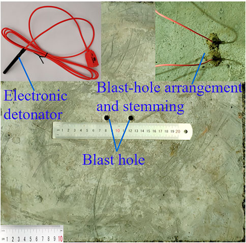
The blasting hole was located on the central line of the surface of the test block, with a diameter of 7.5 mm and a distance of 4 cm from the bottom of the hole to the free surface and 7.0 cm between holes (Figure 1). The experiment used a No. 8 digital electronic detonator to initiate the simulated charge to reduce the influence of the delay time error. The external dimension of the No. 8 digital electronic detonator was φ7.3 × 73 mm2, and the inner diameter of the electronic detonator shell was 6.1–6.4 cm, the filling length was 15 mm, the density was 1.4–1.6 g/m3, and the mass was 0.65 g RDX. The hole orifice was plugged with stemming to reduce the influence of stemming on blasting (Figure 2), and the plugging was to achieve the ideal rock crushing effect (Zhang et al., 2021).
High-Stress Blasting Test Platform
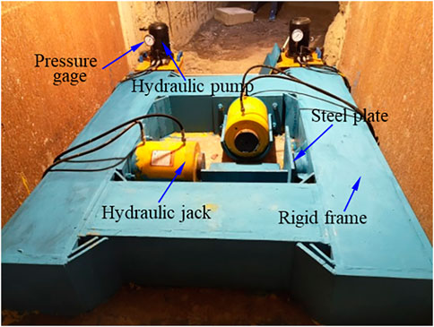
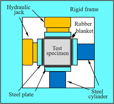
A new type of blasting test system was set up under high stress in the blasting test chamber of Fankou Lead–Zinc Mine, Guangdong Province, to carry out experimental research, which was used to carry out the biaxial loading test on the square block to achieve the pressurization condition of the model block. Figure 3 shows that the test platform mainly consisted of a rigid frame, two hydraulic jacks, two hydraulic pumps, and two rigid pressure heads. The hydraulic jack pushed the rigid indenter to make contact with the test block, the hydraulic pump controlled the loading pressure, and the universal testing machine combined with the pressure sensor was used to calibrate the hydraulic jack, ensuring the accuracy of loading static stress. The loading system applied compressive stress in two directions perpendicular to the free surface of the sample, simulating the bidirectional in situ stress environment of the deep rock mass. The hydraulic cylinder provided 0–60 MPa pressure in two directions, and the pressure gauge on the hydraulic pump was used to measure the output pressure load. As shown in Figure 4, the boundary of the test block was covered with a 20-mm-thick rubber plate to absorb the stress wave at the boundary. Rubber is a kind of polymer material with high elasticity, low impedance, viscoelasticity, shock energy absorption, earthquake resistance, and other mechanical properties. It is often used in structures to reduce the influence of the dynamic load (Qiu et al., 2021). The loading device had a 30-mm-thick steel plate to induce uniform boundary stress. In addition, the unpressurized direction also uses the press to contact the test block.
Experimental Scheme of the Double-Hole Crater Under the Stress Condition
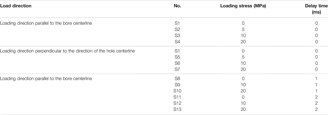
In this study, the experimental research on the double-hole crater was carried out under three different confining pressures: (1) the double-hole crater was detonated simultaneously under unidirectional confining pressure; (2) two-hole simultaneous initiation crater under bidirectional confining pressure; and (3) double-hole short-delay initiation crater under confining pressure loading. A total of sixteen groups of blasting tests were conducted, and the detailed parameters of test confining pressure loading conditions and delay time are shown in Table 1. After placing the test block, the boundary was covered with a rubber plate, and the rubber plate, in turn, was covered with a steel plate. The confining pressure was loaded to the design value using a loading device. The electronic detonator was inserted into the designed hole, and the surface of the model was covered with a cover plate to facilitate the collection of the test block broken by blasting. The electronic detonator was detonated according to the experimental scheme. After each blasting experiment, the data of the crater were carefully measured, and the test pieces were collected, weighed, and screened. On this basis, the relationship between the particle (fragment) size of each test block and the cumulative mass pass rate (%) was established.
Result Analysis
Double-Hole Simultaneous Initiation Crater Under Unidirectional Confining Pressure
1) Blasting test results and analysis under the condition that the direction of the confining pressure loading was parallel to the direction of the hole-to-heart line.
Figure 5 shows the shape of the double-hole simultaneous initiation crater under unidirectional confining pressure when the direction of the confining pressure loading was parallel to the direction of the hole-to-hole line. When no confining pressure was applied, the crater was smaller, and the length of the crater in the hole-to-heart line direction was slightly longer than that in the other direction. However, applying a unidirectional confining pressure in the direction of the hole-to-heart line caused the crater length to gradually increase in the pressurization direction and reduce in the unpressurized direction, especially when the unidirectional pressure reached 20 MPa, the crater diameter in the pressure direction increased from 23.2 to 27.4 cm. This was because the direction of the hole-to-heart line was consistent with the direction of the confining pressure loading, and a stress blind area appeared between two adjacent holes. The applied confining pressure had little effect on the blasting breakage between two holes, but it could promote the breakage around the holes. The volume of the crater first decreased and then increased with the increase in the unidirectional confining pressure, among which the volume of the crater with 5 MPa loading stress was the smallest. This phenomenon shows that low static stress inhibits blasting breakage in the direction parallel to the hole loading. Similar results were reported by Zhang et al. (Zhang et al., 2021). Under the condition of low static stress, the cracks inside the test block are closed. With the increase of static stress, the reflected tensile failure gradually becomes the main factor affecting the formation of the explosion crater. In Figure 6A, the volume of the crater increased from 338.63 cm3 without pressure to 440.64 cm3 with a pressure of 20 MPa. It indicates that the blasting fragmentation range increases with increasing confining pressure. In Figures 6B,C, the average fragmentation (x50) of blasting decreases gradually, indicating that the fragmentation is more uniform with increasing confining pressure.
2) Blasting test results and analysis under the condition that the direction of the confining pressure loading was perpendicular to the direction of the hole-to-heart line
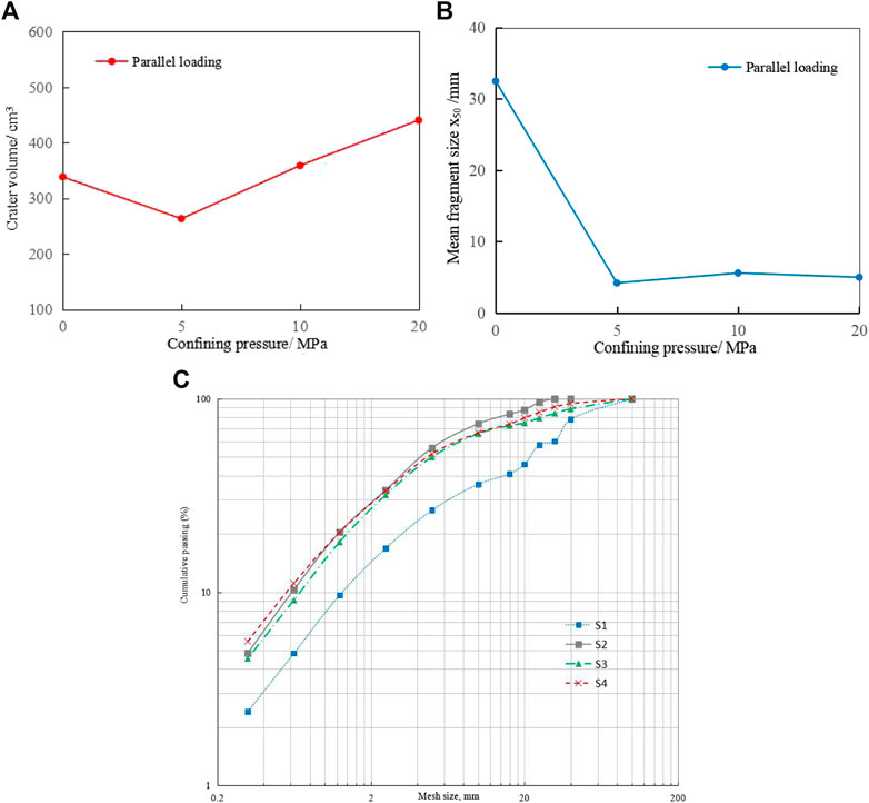
FIGURE 6. Double-hole simultaneous initiation effect under unidirectional confining pressure. (A) Crater volume. (B) Average block size (x50). (C) Distribution functions fitted to sieving results for the S1 ∼ S4 surface profile of the crater.
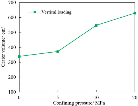
Figure 7 shows the shape of the double-hole simultaneous initiation crater under unidirectional confining pressure when the confining pressure loading direction was perpendicular to the direction of the hole-to-hole line. The crater was smaller without the confining pressure, and the length of the crater in the direction of the hole-to-heart line was slightly longer than that in the other direction. However, the application of unidirectional confining pressure in the direction perpendicular to the hole-to-hole line did not cause much change in the crater length in the direction of the hole-to-hole line; however, the crater length increased in the direction perpendicular to the hole-to-hole line, that is, the pressurization direction, especially in the middle of the hole-to-hole line. This was because the stress in the middle of the hole increased due to the confining pressure applied in the direction perpendicular to the line connecting the hole to the heart, which further promoted the blasting rupture in the middle of the hole. In Figure 8, with the increase of unidirectional pressure, the volume of the crater increases, in which the volume of the crater is 628.32 cm3 under 20 MPa loading stress.
3) Comparing the effects of the crater under different pressurization directions
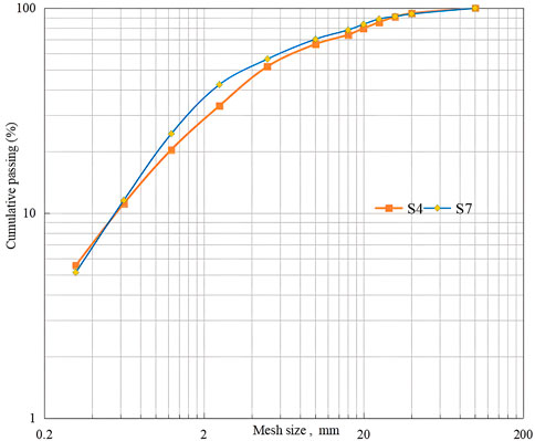
Figures 9, 10 show the comparison of the shapes of double-hole craters under different pressurization directions. The shape of the crater (S4 and S7) was obviously different when the direction of pressurization (S4) was different from that of the hole-to-heart line (S7). When the pressure direction was consistent with the direction of the hole-to-heart line, the crater length in the pressure direction was obviously larger than that in the other pressure scheme. In contrast, the crater length perpendicular to the pressure direction was smaller than that in the other pressure scheme. Figure 11 shows the distribution diagram of blasting fragmentation of two schemes. The distribution of blasting fragmentation was more uniform than that of the other pressurization schemes when the pressurization direction was consistent with the direction of the hole-to-heart line, and its average fragmentation (x50) was also smaller than that of the other scheme. When the pressure direction was parallel to the hole-to-hole line direction, the blasting fragmentation was found to be better than when the pressure direction was perpendicular to the hole-to-hole line direction.
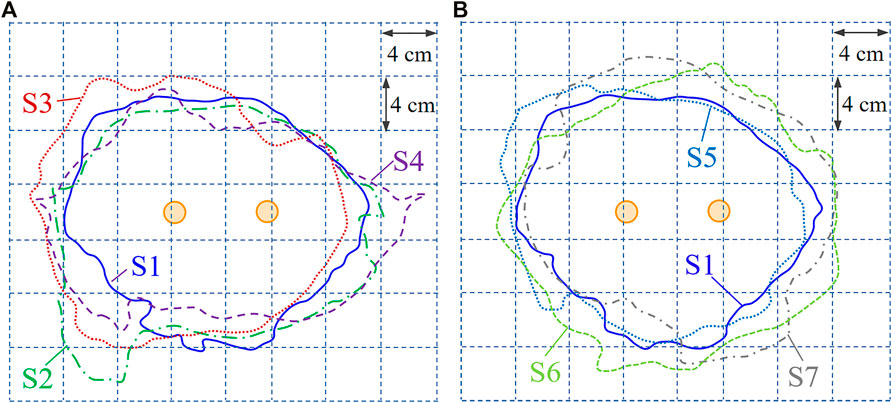
FIGURE 9. (A) Crater surface outline of S1, S2, S3, and S4. (B) Crater surface outline of S1, S5, S6, and S7. Comparison of crater contour under different pressure directions.
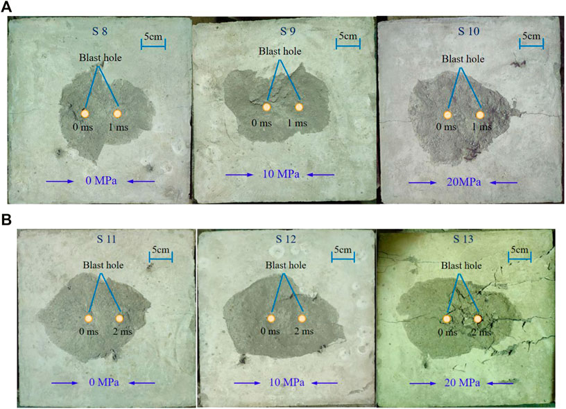
FIGURE 11. Crater shape of double-hole short-delay initiation blasting under confining pressure loading. (A) 1 ms delay between holes. (B) 2 ms delay between holes.
Test Results and Analysis of Double-Hole Short-Delay Blasting Under Confining Pressure Loading
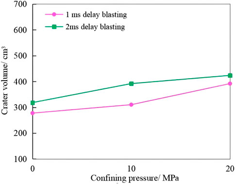
Figure 11 shows the shape of a double-hole short-delay initiation crater under confining pressure loading. When no confining pressure was applied, in S8 and S11, the crater under double-hole short-delay initiation was found to be similar to V-shape. The first blasting hole formed a larger crater, the second blasting hole took the first crater as the free surface for lateral blasting, and the width of the crater on one side of the second blasting hole was smaller in S8, S10, and S12 indicating the influence of delayed initiation, and two adjacent holes failed to form a common crater. However, after applying the confining pressure, the craters of adjacent holes were obviously more uniform and reasonable than those without confining pressure, and the widths of craters at two holes were closer. In addition, the rupture range of S13 blasting is larger than that of S11 without confining pressure due to the confining pressure applied along the direction of the core line of the hole. This showed that under short-delay initiation, double-hole blasting could make good use of confining pressure to form a suitable crater. Figures 12, 13 show the variation in the crater volume with confining pressure under 1 and 2 ms initiation. It can be concluded that with the increase of unidirectional confining pressure and delay time, the crater volume also increases.
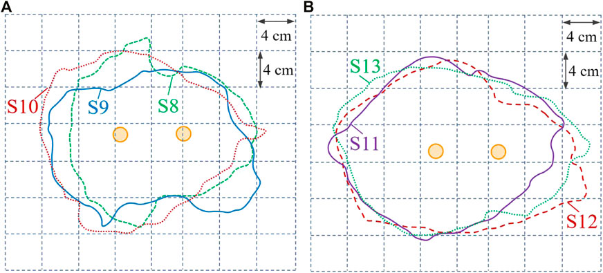
FIGURE 12. Crater contour comparison of delay blasting. (A) Crater surface outline of S8, S9, and S10. (B) Crater surface outline of S11, S12, and S13.
Figure 14 shows the fragmentation distribution of 2 ms initiation under different confining pressures. Figure 14B shows that the average fragmentation x50 after confining pressure loading was smaller than that without confining pressure, and the average fragmentation gradually decreased with an increase in the confining pressure, which was consistent with the research results of Chenhui et al., (2016), indicating that the application of confining pressure under short-delay initiation could effectively improve the fragmentation.
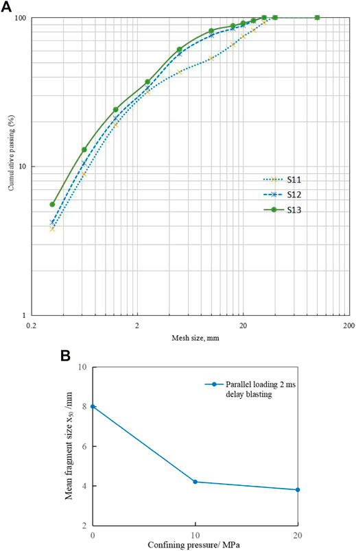
FIGURE 14. Comparison of blasting fragmentation distribution under 2 ms delay. (A) Blasting fragmentation 274 distribution. (B) Average block size.
Discussion
1) Boundary of the experimental model
The boundary of the test block was covered with a 20-mm-thick rubber plate to absorb the stress wave at the boundary. Because of its energy absorption and buffering characteristics, it is often used to reduce the impact of dynamic loads in tests. The 20-mm-thick steel plate is set outside the rubber plate to induce uniform boundary stress and reduce the influence of blasting effect on the boundary (Henrych and Major, 1979).
2) Formation mechanism and time of new free surface in delayed blasting
Figure 15A shows that when two electronic detonators were detonated at the same time, the stress wave loading time was much shorter than the gas pressure. At the same time, the explosive gas did not leak out from the front crater. Therefore, the explosive gases caused by adjacent blasting were gathered through cracks, thus pushing the fractured rocks to form a common crater. If the delay is longer than the new free surface formation time, as shown in Figure 15B, the post-detonated blast hole would have two free surfaces, the free surface and the free surface generated by the previous blast hole. The rock fracture process of double-hole blasting with delayed initiation would be completely separated, making it unable to form the same crater (Qiu et al., 2018).

FIGURE 15. (A) Simultaneous initiation of multiple blast holes. (B) Multiple blast holes with delayed initiation (Qiu et al., 2018).
However, there is still no consensus on the determination of the formation time of the new free surface. The formation time of a new free surface includes three different stages: the first stage is the time required for the explosive stress wave to propagate to the free surface and return to the explosive, and the second stage is the time required for the crack to propagate to the free surface (Henrych and Major, 1979). The third stage is the time required for the crack to continue to expand and form a new free surface with a certain crack width. Therefore, the formation time of the new free surface is as follows:
where W is the minimum burden, CP is the p-wave velocity of the sample (m/s), Lf is the crack length (m), Lf ≈ 1.4W, cf is the average speed of crack expansion, S is the crack width, VS is the initial velocity of crushed rock (normally 10 mm), and VS is the fly-out speed of broken rock (normally 15–25 m/s).
In the experiment of double-hole delay blasting, the formation time of new free surface after the first hole blasting is calculated according to Equation 1 as 558–858 us. Similar results were reported by Chi et al. (2019). The crater of double-hole delay blasting is larger than that of delay blasting, which is consistent with the experimental crater.
3) Fragment Loss
Previous studies showed that smaller fragments consume a lot of energy, which was very important for evaluating the crushing results. Each test block was wrapped in a cuboid of 50 × 50 × 40 cm3 by a steel grid embedded with a thick sponge to reduce the fragment loss of blasting test blocks. Under the same charge and boundary test conditions, a collision may occur between the blasting fragments and the collecting steel grid, which may exist in each explosion. Hence, the impact on the crushing results of each explosion was almost the same. Before the experiment, the hole was blocked with stemming, and the detonator fragments were removed when collecting fragments. The stemming and the removed detonator fragments had the same influence on the explosive crushing results.
Conclusion
1) Static stress significantly affected the shape of the crater. The experimental results of double-hole blasting with two kinds of lateral stress showed that the shape of the crater was extended along the loading direction, and the loading direction became the dominant direction of crack propagation. The blasting experiments with different initiation delay times showed that the loading direction became the dominant direction of radial crack propagation and was not affected by the initiation delay.
2) With the increase of unidirectional confining pressure, the volume of the double-hole blasting crater in different loading directions generally increases. The blasting surface loaded with static stress in the vertical borehole direction is rounder than that loaded with static stress in the horizontal direction. In addition, the volume of the blasting crater loaded with static stress in the vertical borehole direction is larger than that loaded with static stress in the horizontal direction.
3) Static stress and delay time significantly affected the crushing effect of the blasting test block. The experimental results showed that the greater the loading stress is, the better the crushing effect is. The longer the delay time is, the better the crushing effect is. In deep geological engineering, a blasting scheme matching with the in situ stress could be designed to achieve a better rock blasting and crushing effect.
Data Availability Statement
The original contributions presented in the study are included in the article/Supplementary Material, further inquiries can be directed to the corresponding author.
Author Contributions
HC and XQ: investigation, software, and writing—original draft; XS: project administration and supervision; HC and JZ: writing—review and editing; XH and DL: investigation. All authors have read and agreed to the published version of the manuscript.
Funding
This research was funded by the National Natural Science Foundation Project of China, under grant numbers 51874350 and 52004329 and Accurate Delay Rock Breaking Mechanism and Key Technology Innovation Team, under grant number 2020D14043.
Conflict of Interest
Author DL was employed by the company China Nonferrous Metal Mining Group Co., Ltd.
The remaining authors declare that the research was conducted in the absence of any commercial or financial relationships that could be construed as a potential conflict of interest.
Publisher’s Note
All claims expressed in this article are solely those of the authors and do not necessarily represent those of their affiliated organizations, or those of the publisher, the editors, and the reviewers. Any product that may be evaluated in this article, or claim that may be made by its manufacturer, is not guaranteed or endorsed by the publisher.
References
Bangbiao Wu, B., Chen, R., and Xia, K. (2015). Dynamic Tensile Failure of Rocks under Static Pre-tension. Int. J. Rock Mech. Mining Sci. 80, 12–18. doi:10.1016/j.ijrmms.2015.09.003
Chenhui, W., Wancheng, Z., Yu, B., and Leilei, N. (2016). Numerical Simulation on Cutting Seam Cartridge Blasting under Different In-Situ Stress Conditions. Explos. Shock Waves 02. doi:10.11883/1001-1455(2016)02-0161-09
Chi, L. Y., Zhang, Z.-X., Aalberg, A., and Li, C. C. (2019). Experimental Investigation of Blast-Induced Fractures in Rock Cylinders. Rock Mech. Rock Eng. 52, 2569–2584. doi:10.1007/s00603-019-01749-0
Fan, X., Wang, M., and Shi, C. (2009). Study on Effects of Initial Stress on Stress Wave Propagation and Block Movement Law. Chin. J. Rock Mech. Eng. 28, 442–443.
Han, H., Fukuda, D., Liu, H., Salmi, E. F., Sellers, E., Liu, T., et al. (2020). Combined Finite-Discrete Element Modelling of Rock Fracture and Fragmentation Induced by Contour Blasting during Tunnelling with High Horizontal In-Situ Stress. Int. J. Rock Mech. Mining Sci. 127, 104214. doi:10.1016/j.ijrmms.2020.104214
He, C., and Yang, J. (2019). Experimental and Numerical Investigations of Dynamic Failure Process in Rock under Blast Loading. Tunnelling Underground Space Tech. 83, 552–564. doi:10.1016/j.tust.2018.08.047
He, C., Yang, J., and Yu, Q. (2018). Laboratory Study on the Dynamic Response of Rock under Blast Loading with Active Confining Pressure. Int. J. Rock Mech. Mining Sci. 102, 101–108. doi:10.1016/j.ijrmms.2018.01.011
Huo, X., Shi, X., Qiu, X., Chen, H., Zhou, J., Zhang, S., et al. (2021). Study on Rock Damage Mechanism for Lateral Blasting under High In Situ Stresses. Appl. Sci. 11, 4992. doi:10.3390/app11114992
Jayasinghe, L. B., Shang, J., Zhao, Z., and Goh, A. T. C. (2019). Numerical Investigation into the Blasting-Induced Damage Characteristics of Rocks Considering the Role of In-Situ Stresses and Discontinuity Persistence. Comput. Geotechnics 116, 103207. doi:10.1016/j.compgeo.2019.103207
Kutter, H. K., and Fairhurst, C. (1971). “On the Fracture Process in Blasting,” in International Journal of Rock Mechanics and Mining Sciences & Geomechanics Abstracts (Elsevier), 8, 181–202. doi:10.1016/0148-9062(71)90018-0Int. J. Rock Mech. Mining Sci. Geomechanics Abstr.
Lei, Z., and Jiang, X. (2019). Numerical Analysis of Impact of Shot Hole Spacing on Crack Growth in Rock. Chin. J. High Press. Phys. 33, 044103. doi:10.11858/gywlxb.20180683
Li, E., Yang, F., Ren, M., Zhang, X., Zhou, J., and Khandelwal, M. (2021). Prediction of Blasting Mean Fragment Size Using Support Vector Regression Combined with Five Optimization Algorithms. J. Rock Mech. Geotechnical Eng. 13, 1380–1397. doi:10.1016/j.jrmge.2021.07.013
Peng, J., Zhang, F., Du, C., and Yang, X. (2020). Effects of Confining Pressure on Crater Blasting in Rock-like Materials under Electric Explosion Load. Int. J. Impact Eng. 139, 103534. doi:10.1016/j.ijimpeng.2020.103534
Qiu, J., Li, X., Li, D., Zhao, Y., Hu, C., and Liang, L. (2021). Physical Model Test on the Deformation Behavior of an Underground Tunnel under Blasting Disturbance. Rock Mech. Rock Eng. 54, 91–108. doi:10.1007/s00603-020-02249-2
Qiu, X., Shi, X., Gou, Y., Zhou, J., Chen, H., and Huo, X. (2018). Short-delay Blasting with Single Free Surface: Results of Experimental Tests. Tunnelling Underground Space Tech. 74, 119–130. doi:10.1016/j.tust.2018.01.014
Wang, S.-m., Liu, Y.-s., Du, K., and Zhou, J. (2019). Dynamic Failure Properties of sandstone under Radial Gradient Stress and Cyclical Impact Loading. Front. Earth Sci. 7, 251. doi:10.3389/feart.2019.00251
Xiao, S.-Y., Su, L.-J., Jiang, Y.-J., and Liu, Z.-X. (2019). Numerical Analysis of Hard Rock Blasting Unloading Effects in High In Situ Stress fields. Bull. Eng. Geol. Environ. 78, 867–875. doi:10.1007/s10064-017-1067-7
Xiao, Z., Zhang, Z., and Li, D. (1996). The Influence of Initial Stress Field on Blasting, 21. Xuzhou, China: Mei Tan Hsueh Pao J. China Coal Soc.
Yan, P., Zhou, W., Lu, W., Chen, M., and Zhou, C. (2016). Simulation of Bench Blasting Considering Fragmentation Size Distribution. Int. J. Impact Eng. 90, 132–145. doi:10.1016/j.ijimpeng.2015.11.015
Yang, L.-Y., and Ding, C.-X. (2018). Fracture Mechanism Due to Blast-Imposed Loading under High Static Stress Conditions. Int. J. Rock Mech. Mining Sci. 107, 150–158. doi:10.1016/j.ijrmms.2018.04.039
Yang, L., Yang, A., Chen, S., Fang, S., Huang, C., and Xie, H. (2021). Model Experimental Study on the Effects of In Situ Stresses on Pre-splitting Blasting Damage and Strain Development. Int. J. Rock Mech. Mining Sci. 138, 104587. doi:10.1016/j.ijrmms.2020.104587
Yang, R., Ding, C., Li, Y., Yang, L., and Zhao, Y. (2019). Crack Propagation Behavior in Slit Charge Blasting under High Static Stress Conditions. Int. J. Rock Mech. Mining Sci. 119, 117–123. doi:10.1016/j.ijrmms.2019.05.002
Yilmaz, O., and Unlu, T. (2013). Three Dimensional Numerical Rock Damage Analysis under Blasting Load. Tunnelling Underground Space Tech. 38, 266–278. doi:10.1016/j.tust.2013.07.007
Zhang, F., Peng, J., Qiu, Z., Chen, Q., Li, Y., and Liu, J. (2017). Rock-like Brittle Material Fragmentation under Coupled Static Stress and Spherical Charge Explosion. Eng. Geology. 220, 266–273. doi:10.1016/j.enggeo.2017.02.016
Zhang, Y., Ma, J., Sun, D., Zhang, L., and Chen, Y. (2020). AE Characteristics of Rockburst Tendency for Granite Influenced by Water under Uniaxial Loading. Front. Earth Sci. 8, 55. doi:10.3389/feart.2020.00055
Zhang, Z.-X., Qiao, Y., Chi, L. Y., and Hou, D.-F. (2021). Experimental Study of Rock Fragmentation under Different Stemming Conditions in Model Blasting. Int. J. Rock Mech. Mining Sci. 143, 104797. doi:10.1016/j.ijrmms.2021.104797
Zhao, G., Wang, D., Gao, B., and Wang, S. (2017). Modifying Rock Burst Criteria Based on Observations in a Division Tunnel. Eng. Geology. 216, 153–160. doi:10.1016/j.enggeo.2016.11.014
Keywords: in situ stresses, double-hole blasting, borehole expansion, delay initiation, fragmentation of blasting
Citation: Chen H, Qiu X, Shi X, Zhang J, Huo X and Li D (2022) Experimental Study on Fracturing Characteristics of Double-Hole Blasting Under Static Stresses. Front. Earth Sci. 9:829258. doi: 10.3389/feart.2021.829258
Received: 05 December 2021; Accepted: 30 December 2021;
Published: 07 February 2022.
Edited by:
Zhiqiang Yin, Anhui University of Science and Technology, ChinaCopyright © 2022 Chen, Qiu, Shi, Zhang, Huo and Li. This is an open-access article distributed under the terms of the Creative Commons Attribution License (CC BY). The use, distribution or reproduction in other forums is permitted, provided the original author(s) and the copyright owner(s) are credited and that the original publication in this journal is cited, in accordance with accepted academic practice. No use, distribution or reproduction is permitted which does not comply with these terms.
*Correspondence: Xianyang Qiu, cWl1eGlhbnlhbmdfY3N1QDE2My5jb20=
 Hui Chen
 Xianyang Qiu1*