- 1School of Civil Engineering and Architecture, Linyi University, Linyi, China
- 2Linyi City Key Lab of Appraisement and Strengthening in Building Structures, Linyi, China
- 3Key Laboratory of Urban Security and Disaster Engineering, Ministry of Education, Beijing University of Technology, Beijing, China
To simulate the moving boundary problems, the moving least square–based numerical manifold method, abbreviated as MLS-based NMM, was proposed. The MLS-based NMM has been applied successfully to open crack problems, which exhibits the high accuracy and strong robustness. In this study, we extend the MLS-based NMM to simulate the cracked rock considering the contact of the crack surface. Simultaneously, in order to simulate the progressive failure of the cracked rock, an improved strength-based criterion is proposed. The criterion is based on the Mohr–Coulomb criterion and maximum tensile stress criterion. Because rock can be regarded as a quasi-brittle material, a characteristic distance is used to calculate the crack tip stress and correct the crack propagation direction which avoids the phenomenon of “Zig-zag” for the crack propagation path based on the fracture mechanics criterion. The proposed strength-based criterion can acquire the crack tip stress and propagation direction and also realize the automatic determination of the crack propagation length in each step of the crack growth. A Brazilian disc problem and a rectangular plate problem are adopted to verify the numerical model. At last, the numerical model is applied to study the progressive failure process of the rock slope. The results indicate that the proposed method can deal with the crack propagation in the rock and the opening/sliding of rock blocks along discontinuities in a natural way.
Introduction
In rock engineering, rock mass is rich in a large number of discontinuous cracks and joints, which often leads to instability and destruction of the engineering structures. In addition, oil and gas exploitation need to produce directional cracks in the rock mass for increasing the production. Thus, the research of crack propagation in rock mass is of great significance to practical engineering activities.
Under the action of self-weight stress and tectonic stress, cracks may be in a closed state during the development process. In order to accurately simulate the crack propagation in rock mass, the contact between the crack surfaces must be considered. At present, the simulative methods of crack propagation considering contact are mainly divided into three categories: 1) Continuum-based analysis method, such as the finite element method (Li et al., 2005), extended finite element (Liu and Borja, 2008; Xie et al., 2016), mesh-free/mesh-less method (Zhu et al., 2011), scaled boundary finite element method (Zhang P. et al., 2021), and phase-field method (Fei and Choo, 2020). 2) The analysis method based on the discontinuous medium, such as discontinuous deformation analysis (Ning Y. et al., 2011; Zhang K. et al., 2021), discrete element method (Camones et al., 2013; Yan and Zheng, 2017), and peridynamics (Rabczuk and Ren, 2017; Lu et al., 2021).3) The continuous and discontinuous unified analysis method, such as the numerical manifold method (Wu and Wong, 2012; Liu et al., 2017; Zheng et al., 2019; Yang et al., 2020b). It is not an easy task for continuum-based analysis methods to simulate complex crack problems. For example, it is difficult to construct the level set of the extended finite element to describe the position of the complex crack, and the finite element method requires that the crack tips stay on the edge of the element at each step of crack propagation. The phase-field method requires additional calculation of the field and encryption of the grid near the crack, which results in low computational efficiency. The analysis method based on the discontinuous medium can deal with the complex crack problem well, but the calculation accuracy is not high in the continuous area. Although there are corresponding coupling methods, the data transmission problem at the junction of different areas needs to be considered, which is more difficult to handle. In view of this, the numerical manifold method (NMM) (Shi, 1991) was proposed, which belonged to the continuous and discontinuous unified analysis method.
At the beginning of the NMM, it aimed to solve the continuous and discontinuous problems in geotechnical engineering under a unified framework. The continuous and discontinuous solutions were implemented by using two sets of covering systems, which were physical and mathematical covers, and the penalty method for imposing contact boundary conditions with an open-close iteration determining the contact states. After 30 years of development, it has made great achievements in basic theories (Liu and Zheng, 2016; Yang and Zheng, 2017; Liu et al., 2020; Liu and Zheng, 2021) and applications (Jiang et al., 2010; Wang and Gong, 2012; Zheng et al., 2015b; Fan et al., 2016; Chen and Li, 2017; Zhang et al., 2018; Guo et al., 2019; Yang et al., 2019; Yang et al., 2020a). The studies on crack propagation using the NMM are discussed in detail below.
According to whether the crack tips are allowed to stay inside the physical patch with crack propagation, the NMM can be divided into two categories. The first type is that only the crack tips are allowed to stay at the edge of the physical patch. Based on a local mesh refinement and auto-remeshing scheme, Tsay et al. (1999) carried out the simulation of crack propagation using the NMM. Later, Chiou et al. (2002) combined the virtual crack extension method to simulate the mixed mode fracture propagation. Zhang G. et al. (2010) applied the second-order manifold method to simulate the toppling failure of the rock slope. Considering the crack surface contact, the stability analysis of the rock slope was studied based on the Mohr–Coulomb criterion with a tensile cutoff (Ning Y. J. et al., 2011; An et al., 2014). Based on a cover refinement method, Yang et al. (2014) modeled cracks with contact. The second type is that the crack tips are allowed to stay at any position of physical patch. In order to reflect the singularity and discontinuity near the crack tip, a local approximation function is introduced to improve the solution precision (Li and Cheng, 2005; Ma et al., 2009; Liu et al., 2021a), which is also known as the enriched NMM. Most studies have focused on open cracks (without considering the contact of the crack surface), such as tensile/tension-shear crack propagation (Zhang H. H. et al., 2010; Yang et al., 2016a; Yang et al., 2016b; Xu et al., 2019) and hydraulic fracturing modeling (Yang YT et al., 2018). Frictional contact cracks using the enriched NMM are studied in detail in the literature (Wu and Wong, 2012; Liu et al., 2017; Zheng et al., 2019). The enriched NMM has successfully simulated the failure process of the rock slope considering the contact of the crack surface (Wong and Wu, 2014; Yang et al., 2020b). Obviously, if only the crack tip is allowed to stay at the edge of the physical patch and the local mesh refinement technology near the crack tip is not adopted, the calculation error will increase when the mesh is coarse.
In order to further improve the solving accuracy of the NMM and its ability to deal with moving boundary problems, the moving least square–based NMM (abbreviated as the MLS-based NMM) was proposed (Zheng et al., 2014), which allowed the crack tips to exist in the physical patch. Compared with the traditional NMM, the MLS-based NMM without changing the arrangement of mathematical nodes can improve the approximate precision of partition of unity by increasing the size of the constructing mathematical patch and choosing the order of basis function and the type of weight function constructing MLS. Of course, the MLS-based NMM also inherits the advantage of the NMM to improve the approximate accuracy by constructing a local approximation function (increasing the order or reflecting the analytical solution of the local characteristics of the problem domain) (Zheng et al., 2014; Zheng and Xu, 2014), and it is easy to implement p-adaptive analysis (Liu and Xia, 2017). It can solve the continuous and discontinuous problems in a unified framework. Through the construction of tailored local approximate functions, the essential boundary condition and material interface continuity can be imposed exactly (Zheng et al., 2017). The MLS-based NMM for seepage analysis (Zheng et al., 2015b) and 3D static and dynamic analyses of the continuous elastic body (Liu et al., 2019) have also been presented.
At present, the MLS-based NMM is mainly used for open crack analysis (Zheng et al., 2014; Zheng et al., 2015a; Li et al., 2018a; Li et al., 2018b; Li et al., 2021). This study will expand the MLS-based NMM to study the closed crack propagation considering the contact boundary conditions of the crack surface. So, a variational equation for conservation of momentum considering the contact will be established and discretized by the MLS-based NMM.
The maximum circumferential stress criterion based on fracture mechanics is only applicable to the case where the type I stress intensity factor (KI) is greater than or equal to zero (Wu and Wong, 2012). However, when the criterion is used to simulate compression-shear cracks, KI is usually less than zero, which is actually unreasonable. The simulated results based on the fracture mechanics criterion are also given in section 6, and it is found that the propagation path is “Zig-zag”, which deviates from the reality. Therefore, inheriting the literature (Zheng et al., 2019; Yang et al., 2020b), this study proposes an improved strength based on the Mohr–Coulomb criterion and maximum tensile stress criterion, including the crack initiation criterion, propagation direction, and propagation length and verifies its validity through numerical examples.
Section 2 gives a detailed introduction to the MLS-based NMM, including MLS, cover systems, global approximation function space, and background integration mesh. In section 3, the method of contact treatment in the MLS-based NMM, the inheritance strategy of the degree of freedom during crack propagation, and the variational equation of momentum conservation considering contact are introduced, and the corresponding solving scheme of the MLS-based NMM is established. In section 4, an improved strength-based criterion is proposed as the crack propagation criterion. Section 5 gives the detailed process of program implementation. In section 6, the validity of the proposed method is verified by some typical examples. Some conclusions are drawn in the last section.
An Introduction to the MLS-Based NMM
Moving Least Square Method
In the MLS-based NMM, the core idea is to utilize the moving least squares (MLSs) instead of the shape function of the finite element in the NMM as the function of partition of unity. MLSs will be briefly introduced below. The “node” mentioned in this section is the “mathematical node” of the MLS-based NMM.
In a two-dimensional problem domain (Ω), let the value of discrete nodes of a scalar function (u) be ui = u (ri), i = 1, … ,m, where m is the number of nodes and ri is the coordinate of the ith node. Here, ri = (xi, yi), where xi and yi are the x and y coordinates of the ith node in the coordinate system.
In Ω, the local approximation function of any point (r) constructed by moving least squares is
Here,
The sum of the weighted squares of errors at each discrete node (
where N is the number of nodes whose influence domain can cover r, and
Here,
where z represents
After taking the minimum value of J in Eq. 3, the following equation can be obtained
where
Substituting Eq. 6 into Eq. 1 and making
Then, the MLS is
MLS owns compactness and partition of unity and also has the ability to regenerate the base, namely,
When
Cover System of the MLS-Based NMM
Since MLS owns the property of partition of unity, it is natural to choose MLS as the partition of unity function of the NMM. Then, the interpolation of the NMM will be replaced by the shape function of MLS, which can improve the accuracy of interpolation and enhance the adaptability to the problem. The following is a brief introduction to the cover system of the MLS-based NMM.
As shown in Figure 1, mathematical nodes (
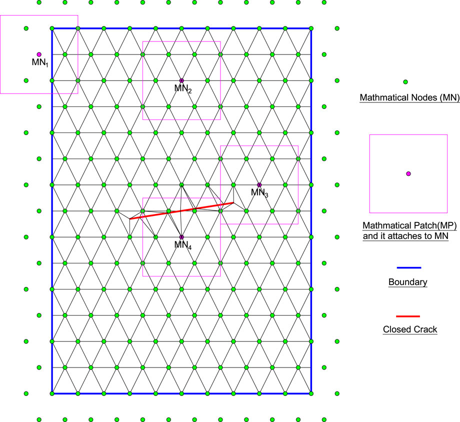
FIGURE 1. Mathmatical nodes, background integration mesh, and some mathamatical patches for the cracked body in the MLS-based NMM.
Cutting the mathematical patches through physical boundaries (such as the boundaries of the problem domain and cracks) to generate corresponding physical patches (
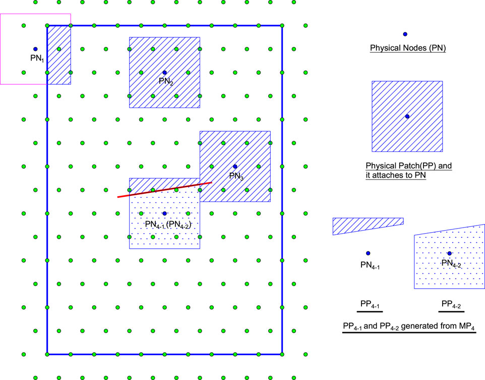
FIGURE 2. Some typical physical patches and they attach to physical nodes for the cracked body in the MLS-based NMM.
In addition, the crack tips are allowed to stay in the physical patch, as PP3 in Figure 2, which is called the singular physical patch (Williams’s displacement series is defined on it to reflect the singularity and discontinuity near the crack tip). When the mathematical patch is cut completely by the cracks, such as MP4 in Figure 1, two physical patches (PP4-1 and PP4-2) and corresponding physical nodes (PN4-1 and PN4-2) of Figure 2 are generated. Such treatment will allow the MLS-based NMM to naturally simulate the discontinuity of cracks (Zheng et al., 2014).
For convenience, after merging physical patches and physical nodes, they become
To sum up, the mathematical cover (
Global Approximation Function Space
The global approximate function space of the MLS-based NMM (denoted as
where "
In this study, two types of physical patch are defined. One is the singular physical patch (S-PP) containing the crack tips, and the other is the ordinary physical patch (O-PP) without the crack tips. For example, PP1, PP2, PP4-1, and PP4-2 belong to the ordinary physical patch, and PP3 belongs to the singular physical patch in Figure 2. Different local approximation functions will be defined in different physical patches to achieve a better local approximate accuracy.
On O-PP, only constant order is taken
In order to reflect the singularity of the crack tip, Williams’s displacement series (Williams, 1957) is added on Eq. 17. Then, the local approximation function on S-PP is
Here, nk is the number of crack tips in S-PP.
where
Here,
Combining Eq. 17 and 18, a unified expression can be obtained
where
Then, from Eq. 16, the global approximate function of the MLS-based NMM is
Substituting Eq. 22 into Eq. 25 to get
where
Here,
Background Integration Method
Like the element-free Galerkin method (EFG), the MLS-based NMM also adopts the background integration mesh to implement numerical integration. The background mesh refers to the non-overlapping and non-gap grids in the problem domain. In the MLS-based NMM, the background mesh is only used to compute integrals. Therefore, there is no need to pay too much attention to the mesh quality; its generation is simpler and more flexible than the FEM. Therefore, based on the regular arrangement of mathematical nodes, this study directly generates a basic integration mesh by connecting adjacent mathematical nodes. Afterward, they are cut and subdivided into triangular grids through physical boundaries, and the background integration mesh of the MLS-based NMM is finally obtained, as shown in Figure 1. For each triangle, the Gauss integral scheme of the literature (Yang et al., 2020b) is adopted, and the singular integral is adopted near the crack tip, referring to the literature (Zheng and Xu, 2014).
Variational Equation of Momentum Conservation Considering Contact
In this study, the MLS-based NMM inherits the contact processing technology of the NMM (Shi, 1991; Zheng et al., 2019; Yang et al., 2020b), as follows: 1) Search and judgment of the contact pair. All contact pairs of angle–angle, angle–edge, and edge–edge are all transformed into the contact pairs of angle–edge. 2) Using the penalty method to impose contact constraints. 3) Adopting an open-close iteration to solve the contact problem.
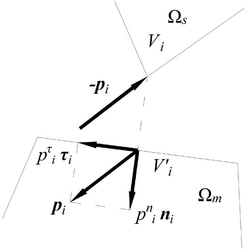
The background integration mesh matches the boundary of the problem domain, so the background integration mesh is applied to discretize the contact boundary (as shown in Figure 1) and search the contact pairs. All contact pairs are eventually converted to the contact pairs of angle–edge in the MLS-based NMM (see Figure 3). Next, the contact pairs of angle–edge are analyzed, and the variational equation of momentum conservation considering the contact is established and discretized by the MLS-based NMM.
Contact Analysis of the Closed Cracked Body
Figure 3 shows a force analysis of the ith contact pair about angle–edge. A vertex (Vi) of the slave block (
or
where
Here, ni and τi represent the inner normal and tangential direction vectors of the contact edge, respectively.
When the current time step finishes, the normal relative displacement between Vi and
And, the relative tangential displacement is
where
The contact relationship must satisfy the normal contact condition as
Here, three formulas are expressed as the non-embedded condition, the normal non-pulling condition, and the complementary condition in sequence. It is worth noting that when the penalty method is applied to impose the contact boundary condition, certain embedding will occur between the contact bodies.
The tangential contact condition using the Mohr–Coulomb friction criterion should be
where μ is the coefficient of friction, and c is cohesion.
The Inheritance Strategy of Extended Freedoms
In the MLS-based NMM, as the crack propagates, the type of physical patch changes accordingly. As shown in Figure 4, PP1 ∼ PP9 (blue nodes) are singular physical patches, PP10∼PP18, PP23, and PP24 are ordinary physical patches, and PP19∼PP22 (each blue box represents two ordinary physical patches) are physical patches generated by crack cutting at time t. However, at time t+Δt after crack propagation, the singular PP1∼PP9 and ordinary PP23 and PP24 at time t will change into the physical patches generated by the new crack (red dotted line) cutting, and the ordinary PP10∼PP18 will change into the new singular physical patches. Therefore, the degrees of freedom on these physical patches will change at the adjacent moments of crack propagation, which will cause the problems of related variables (such as displacement and velocity.) to inherit and transfer. If there is no suitable inheritance strategy, the energy before and after crack propagation will be inconsistent, which seriously affects the accuracy of simulating dynamic crack propagation. This issue has also been studied by Réthoré et al. (2005) and Zheng et al. (2019) et al.
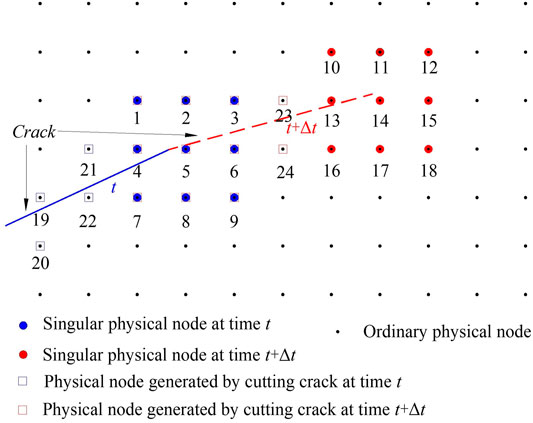
FIGURE 4. Schematic diagram of the physical patch type changing with crack propagation (The physical nodes are directly used to replace corresponding the physical patches for description in the figure).
When the crack propagates, the configuration of the computational domain changes. In other words, the termination configuration of the current time step is different from the initial configuration of the current time step.
Let Y represent the field variable that changes with time; then, the calculation process from tn to tn+1 is expressed as follows:
where Yn is the value of the field variable at time tn,
Converting the variable values on the physical patches to the Gaussian integration points, the first transformation of Eq. 38 is accomplished through processing the variable values on the Gaussian integration points. In other words, using the variable values on the Gaussian integration points before crack propagation to calculate the variable values on the newly generated Gaussian integration points by Shepard interpolation. After the first step is completed, the second step is completed according to the idea of first discrete time in discrete space (Zheng et al., 2019). The second step is described in detail below.
Variational Equation of Momentum Conservation and its Discretization
Without considering the damping effect, for linear elastic media, the penalty method is adopted to apply the displacement boundary and contact boundary; then the variational form of the momentum equation is
where ∑ is the strain tensor,
If the ith contact pair is in a bonded state, then
If the contact state is the sliding state, then
Here,
If the contact state is an open state, then
In Eqs 41 and 42,
With the inheritance strategy in Section 3.2 and constant acceleration method of Newmark, Eq. 39 is discreted by Eq. 26, namely,
where
And, the initial stress matrix is
In Eq. 48, D is the elastic matrix. In Eqs 46 and 52,
For
sliding
and open
After the completion of the open-close iteration,
Here,
An Improved Strength-Based Criterion for Crack Propagation
This section introduces the crack propagation criteria based on the strength criterion, including approximate crack tip stress, crack propagation direction, crack initiation criterion, and crack propagation length. The criterion is inherited and developed from the literature (Zheng et al., 2019; Yang et al., 2020b).
Crack Tip Stress and Crack Propagation Direction
The crack tip stress needs to be determined for the strength criterion. However, the stress at the crack tip is singular in linearly elastic media (Williams, 1957). In other words, the closer it is to the crack tip, the greater the stress is. Theoretically, the crack tip stress is infinite. But the crack tip stress cannot be infinite in practice. So how to calculate the representative crack tip stress is a key issue.
In the NMM, the average stresses on the physical patches near the crack tip are generally calculated by the area weighting method, which is adopted to interpolate the crack tip stress. The interpolation method can apply the shape function of the finite element method or MLS and so on (Ning Y. et al., 2011; An et al., 2014; Yang et al., 2020b). However, the kind of method is actually the approximate method, which cannot explain its rationality and accuracy. A large number of studies (Aliha et al., 2010; Gupta et al., 2015; Xie et al., 2017) show that for quasi-brittle materials, the influence of T-stress on the crack propagation direction should be considered, and there is a characteristic distance rc (Taylor et al., 2004), which is generally taken as
where
In view of this, this study gets a set of stresses at a distance of rc from the crack tip (see Figure 5). The crack tip stress will be determined by analyzing a set of stresses according to the failure criterion. Here, the characteristic distance (see the Eq. 61) is used, so the crack tip stress may be influenced by T-stress.
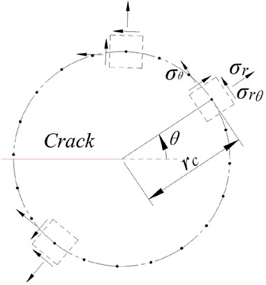
FIGURE 5. Schematic diagram of stress distribution on a circle with the crack tip as the center and rc as the radius.
The Mohr–Coulomb criterion and the maximum tensile stress criterion are selected as the failure criterion and determine the direction of crack propagation. Taking the compressive stress as positive, the critical stress of the Mohr–Coulomb criterion is
where
And, the maximum tensile stress criterion is
Considering the poor tensile properties of quasi-brittle rock materials, the failure criterion is mainly based on the maximum tensile stress criterion. Then, the steps to determine the crack tip stress are shown as follows.
First, the stresses on the circle whose center is located at the crack tip with the radius of rc are calculated by the Shepard interpolation of the stresses of nearby Gaussian points. Furthermore, the maximum circumferential stress and tangential stress are found from the stresses. Second, according to Eqs 62 and 63, the maximum stresses are determined whether failure will occur. And lastly, if the failures occur on the basis of Eqs 62 and 63, or the failure occurs on the basis of Eq. 62, the stress of this position of the maximum circumferential stress is the crack tip stress. If the failure occurs only on the basis of Eq. 63, the stress of this position of the tangential stress is the crack tip stress.
After the crack tip stress is determined, the crack propagation direction is determined according to the maximum tensile stress criterion or Mohr–Coulomb criterion. If tensile failure occurs according to the crack tip stress, the crack propagation direction is perpendicular to the direction of minimum principal stress (
Crack Growth Length
In the literature studies (Ning Y. J. et al., 2011; An et al., 2014) using the strength criterion as the crack growth criterion, the crack growth length is often specified artificially through experience. So the simulative results may be affected by the specified crack growth length. Therefore, this study adopts the method proposed by Zheng et al. (2019), which can directly and automatically calculate the crack propagation length. The method is briefly described as follows.
First, the stresses of any point are calculated in the crack propagation direction. Then, the failure of these points is judged according to Eqs 62 and 63. According to the destructive points, the crack propagation length (L) will be determined. Since the crack tip stress comes from a distance of rc from the crack tip in this study, it is necessary to further correct whether the crack propagates. When L < r¸c, the crack does not propagate. When L ≥ rc, the crack propagates. As shown in Figure 6, when the result is L1, the crack does not propagate, and when the result is L2, the crack propagates.
Program Implementation
1) Entering geometric and physical parameters.
2) The mathematical nodes and corresponding mathematical patches are arranged regularly to generate the mathematical cover and background integration mesh.
3) Cutting the mathematical patches by the physical boundary to form the physical patches and constituting the physical cover. Processing the background integration mesh to generate the final background integration mesh.
4) Establishing a solution system for the cracked rock using the MLS-based NMM, in which the contact boundary is imposed by the penalty method.
5) Solving the nth time step.
i) Searching the contact pairs of angle–edge and solving the problem by open-close iteration.
ii) Determining whether the crack propagates in accordance with the improved strength-based criterion. If yes, performing the (iii)∼(VI). If not, determining whether the total time step is reached (If not, performing the (n+1)-th time step. If yes, performing the 6.).
iii) According to the improved strength-based criterion, determining the crack propagation direction and length.
IV) Updating the physical cover and background integration mesh.
V) Updating the stresses of integral points, which applies the Shepard interpolation to calculate near the expanding crack.
VI) Determining whether the total time step is reached. If not, performing the (n+1)-th time step. If yes, performing the 6.
6) Post-processing of results.
Numerical Examples
Several typical examples are simulated to verify the accuracy and ability of the proposed method. The square form of mathematical patches (the influence domain of the MLS node) is selected, and its half-length is 1.6 h, where h is the distance between adjacent mathematical nodes. In addition, the crack growth criterion based on the fracture mechanics criterion is also adopted for comparison [see Li et al. (2018a)], where the crack growth length at each step is set as 1.1 h. The results are also compared with related numerical simulation results (Li et al., 2005; Zheng et al., 2019) and experimental results (Haeri et al., 2014; Haeri et al., 2015). It is worth noting that the penalty method is adopted to impose the displacement boundary condition and contact boundary condition. In this study, we do not discuss the selection of the optimal penalty factor. Thus, we choose 105 × E as the penalty factor for the displacement boundary, where E represents the Elastic modulus. For the contact boundary, the stiffness of the normal contact spring is E, while the stiffness of the normal contact spring is 0.4 × E.
In this study, when the crack grows, the background integration mesh and the physical boundaries are updated automatically by the loop updating technology of the NMM (Zheng et al., 2019; Yang et al., 2020b). Furthermore, the physical cover is updated through the updated physical boundaries cut the mathematical patches.
Brazilian Disc With Pre-crack
The Brazilian disc test is an effective method to determine the tensile strength of the brittle rock. Two cases of a Brazilian disk containing one pre-crack and two pre-cracks are considered in this section. Among them, the diameter of the disc is 100 mm, and the platform of compression is 6.2 mm (that is, the platform forms a central angle of 7.2 at the center of the circle).
The size of the rigid plate is 100 mm in length and 4 mm in width. The material parameters of rock are Elastic modulus E = 10GPa, Poisson’s ratio ν = 0.25, density ρ = 2500 kg/m3, internal friction angle
(a) A Brazilian disk with a crack
Figure 7A shows a schematic diagram of a Brazilian disc with a crack, where the length of the crack is 30 mm. Figure 7B shows the discrete model with 584 mathematical nodes. The load is applied through rigid plates at both ends of the disk with an average loading speed of 1.0 × 10⁻⁶ m/step.
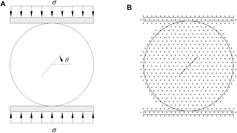
FIGURE 7. Brazilian disk with a crack (A) Geometry and loading conditions (B) Discrete model (taking θ = 45° as an example).
Figure 8 shows the crack propagation paths with crack inclination angles of 30°, 45°, and 60°, including the simulation results of the proposed method (the MLS-based NMM based on the improved strength-based criterion), the MLS-based NMM based on the fracture mechanics criterion, the NMM from the literature (Zheng et al., 2019), DDA from the literature (Ning Y. et al., 2011), and the experiment from the literature (Haeri et al., 2014).
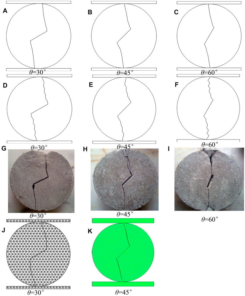
FIGURE 8. Crack propagation path of a Brazilian disk with a crack under compression. (A–C) The proposed method, (D–F) MLS-based NMM based on the fracture mechanics criterion, (G–I) Experimental result (Haeri et al., 2014) (J) the NMM (Zheng et al., 2019), and (K) DDA (Ning Y. et al., 2011).
It can be seen from the results in Figure 8 that the dynamic crack propagation path based on the improved strength-based criterion and fracture mechanics criterion using the MLS-based NMM is basically consistent with the reference results and experimental results. But the results based on the improved strength-based criterion are smoother than those based on the fracture mechanics criterion. It should be noted that the crack propagation length based on the improved strength-based criterion is automatically generated at each step, while the crack propagation length based on the fracture mechanics criterion is fixed as 1.1h.
(b) A Brazilian disk with parallel multiple cracks
Figure 9A shows a Brazilian disk with parallel multiple cracks with θ = 45°, all of cracks are 20 mm in length. The distance between the centers of the two cracks is s = 20 mm. The discrete model with 1,132 mathematical nodes is shown in Figure 9B. The load is applied through rigid plates at both ends of the disk with an average loading speed of 1.0 × 10⁻⁷ m/step.

FIGURE 9. Brazilian disk with parallel multiple cracks (A) Geometry and loading conditions (B) Discrete model.
The simulation results of the proposed method are shown in Figures 10A,B and compared with the experimental results in the literature (Haeri et al., 2015). Although there are slight differences, the authors think that the results of the proposed method are reasonable. Because the example is a symmetric structure and enforced by the symmetric load, the crack should propagate symmetrically. Furthermore, the results of the proposed method also show the symmetry of crack propagation. The results suggest that the damage is caused by the penetration and intersection of cracks.
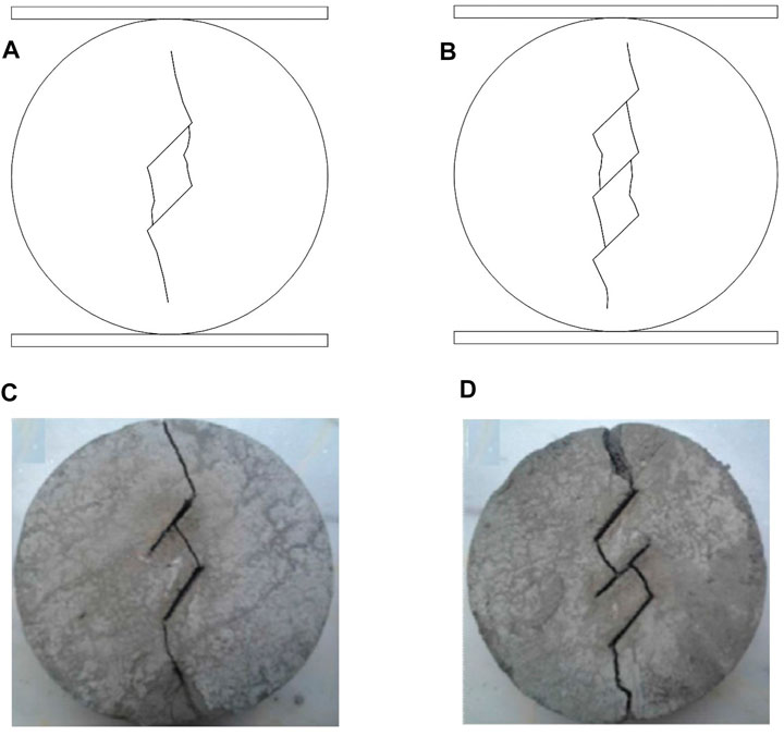
FIGURE 10. Crack propagation path of a Brazilian disk with parallel multiple cracks under compression. (A) The result of parallel double cracks using the proposed method, (B) The result of three parallel cracks using the proposed method, and (C,D) Experimental result (Haeri et al., 2015).
Rectangular Plate With Pre-crack
Figure 11A shows a rectangular plate with an oblique crack in the middle. The top and bottom of the plate are subjected to compressive loads. The size of the plate is 62 mm in width and 110 mm in height. The initial crack length is 20mm, and the angle between the crack and the horizontal direction is θ. The load is applied through rigid plates at both ends of the disk with an average loading speed of 1.0 × 10⁻⁶ m/step. The size of rigid plates is 62 mm in width and 5 mm in height. The material parameters of rock are Elastic modulus E = 10 GPa, Poisson’s ratio ν = 0.25, density ρ = 2500 kg/m3, internal friction angle
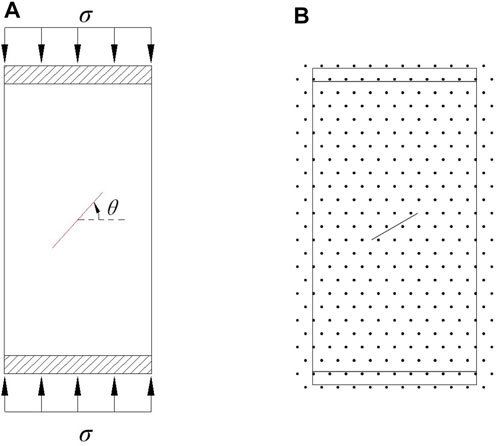
FIGURE 11. Rectangular plate with a crack (A) Geometry and loading conditions (B) Discrete model (taking θ = 30° as an example).
Figure 12 shows the crack propagation paths at crack angles θ = 30°, 45°, and 60°, respectively. Likewise, the simulation results of the MLS-based NMM based on the fracture mechanics criterion are also presented for comparison. In Figures 12G,H, the simulation results using the NMM (Zheng et al., 2019) and RFPA (Li et al., 2005) are also given.

FIGURE 12. Crack propagation path of a rectangular plate with a crack under compression. (A–C) The proposed method, (D–F) MLS-based NMM based on the fracture mechanics criterion, (G) NMM (Zheng et al., 2019), and (F) RFPA (Li et al., 2005)
From the results, the proposed method can simulate the crack propagation well, which is similar to the results in the literature. The simulation results of the MLS-based NMM based on the fracture mechanics criterion also show the phenomenon of “Zig-zag” like the Brazilian disk experiment in Section 6.1, but the overall trend of crack growth is consistent with other methods. This means that the cracks will expand towards the place of the load and gradually tend to be parallel to the direction of the load. The phenomenon of oscillation may be caused by the inaccurate calculation of the dynamic stress intensity factor after considering the contact or the inaccurate crack propagation length at each step.
A Slope With a Single Inclined Crack
A homogeneous slope with a single inclined crack is shown in Figure 13A from the literature (Yang et al., 2020b). Figure 13A gives the geometry and boundary conditions of the slope, and only the gravity load is imposed to the slope body. In order to make the slope be more easily damaged, the overload method is adopted. In the simulation process, the gravity load is 10 times greater than the actual value of gravity. The actual material parameters of this example are Elastic modulus E = 35 GPa, Poisson’s ratio ν = 0.15, density ρ = 3200 kg/m3, internal friction angle
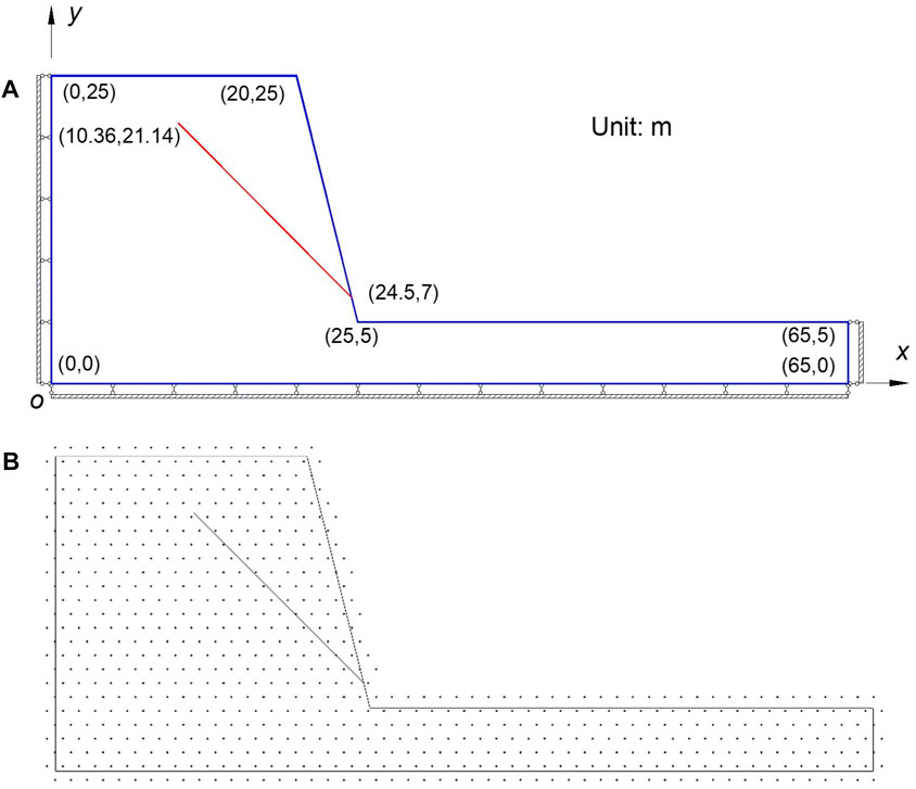
FIGURE 13. Slope with a single inclined crack (A) Geometry and boundary conditions (B) Discrete model.
Conclusion
In this study, the MLS-based numerical manifold method is extended to model the crack propagation of the cracked rock considering the contact of the crack surface. The inheritance strategy of the degree of freedom during crack propagation and the variational equation of momentum conservation considering contact are established for the MLS-based NMM. Using the penalty method to impose contact constraints and adopting open-close iteration to solve the contact problem are all presented. Simultaneously, in order to simulate the progressive failure of the cracked rock, an improved strength-based criterion is proposed. Several typical examples are simulated. Some conclusions are drawn as follows:
1) The MLS-based NMM considering the contact of the crack surface allows the crack tip to stay in any position and can simulate the complex contact boundary.
2) The improved strength-based criterion incorporated into the MLS-based NMM can automatically compute the approximate crack tip stress, crack propagation direction, crack initiation criterion, and crack propagation length.
3) The results of typical examples indicate that the proposed method can deal with the crack propagation in a rock and the opening/sliding of rock blocks along discontinuities in a natural way.
In practice, the rock mass contains complex cracks and is in 3- dimensional space. So, the proposed method warrants further investigation in the future.
Data Availability Statement
The original contributions presented in the study are included in the article/Supplementary Material; further inquiries can be directed to the corresponding author.
Author Contributions
WL contributed to the study design. Heng Zheng consulted the study. XY interpreted the data. CJ was responsible for searching references. WL and XS drafted the manuscript.
Funding
This study is supported by the National Natural Science Foundation of China, under Grant Nos. 11902134 and 51904149, and the Youth Natural Science Foundation of Shandong Province (Nos. ZR2020QD126 and ZR2019BEE013).
Conflict of Interest
The authors declare that the research was conducted in the absence of any commercial or financial relationships that could be construed as a potential conflict of interest.
Publisher’s Note
All claims expressed in this article are solely those of the authors and do not necessarily represent those of their affiliated organizations, or those of the publisher, the editors, and the reviewers. Any product that may be evaluated in this article, or claim that may be made by its manufacturer, is not guaranteed or endorsed by the publisher.
References
Aliha, M. R. M., Ayatollahi, M. R., Smith, D. J., and Pavier, M. J. (2010). Geometry and Size Effects on Fracture Trajectory in a limestone Rock under Mixed Mode Loading. Eng. Fracture Mech. 77 (11), 2200–2212. doi:10.1016/j.engfracmech.2010.03.009
An, X., Ning, Y., Ma, G., and He, L. (2014). Modeling Progressive Failures in Rock Slopes with Non-persistent Joints Using the Numerical Manifold Method. Int. J. Numer. Anal. Meth. Geomech. 38 (7), 679–701. doi:10.1002/nag.2226
Camones, L. A. M., Vargas, E. d. A., de Figueiredo, R. P., and Velloso, R. Q. (2013). Application of the Discrete Element Method for Modeling of Rock Crack Propagation and Coalescence in the Step-Path Failure Mechanism. Eng. Geology. 153, 80–94. doi:10.1016/j.enggeo.2012.11.013
Chen, Y. L., and Li, L. X. (2017). Modeling Phase Change Problems Using a New Implementation of the Numerical Manifold Method. Appl. Math. Model. 48, 39–52. doi:10.1016/j.apm.2017.01.022
Chiou, Y.-J., Lee, Y.-M., and Tsay, R.-J. (2002). Mixed Mode Fracture Propagation by Manifold Method. Int. J. Fracture 114 (4), 327–347. doi:10.1023/a:1015713428989
Fan, H., Zheng, H., and He, S. (2016). S-R Decomposition Based Numerical Manifold Method. Comput. Methods Appl. Mech. Eng. 304, 452–478. doi:10.1016/j.cma.2016.02.033
Fei, F., and Choo, J. (2020). A Phase-Field Method for Modeling Cracks with Frictional Contact. Int. J. Numer. Methods Eng. 121 (4), 740–762. doi:10.1002/nme.6242
Guo, H., Zheng, H., and Zhuang, X. (2019). Numerical Manifold Method for Vibration Analysis of Kirchhoff's Plates of Arbitrary Geometry. Appl. Math. Model. 66, 695–727. doi:10.1016/j.apm.2018.10.006
Gupta, M., Alderliesten, R. C., and Benedictus, R. (2015). A Review of T-Stress and its Effects in Fracture Mechanics. Eng. Fracture Mech. 134, 218–241. doi:10.1016/j.engfracmech.2014.10.013
Haeri, H., Khaloo, A., and Marji, M. F. (2015). Experimental and Numerical Analysis of Brazilian Discs with Multiple Parallel Cracks. Arab J. Geosci. 8 (8), 5897–5908. doi:10.1007/s12517-014-1598-1
Haeri, H., Shahriar, K., Marji, M. F., and Moarefvand, P. (2014). Experimental and Numerical Study of Crack Propagation and Coalescence in Pre-cracked Rock-like Disks. Int. J. Rock Mech. Mining Sci. 67, 20–28. doi:10.1016/j.ijrmms.2014.01.008
Jiang, Q.-h., Deng, S.-s., Zhou, C.-b., and Lu, W.-b. (2010). Modeling Unconfined Seepage Flow Using Three-Dimensional Numerical Manifold Method. J. Hydrodyn 22 (4), 554–561. doi:10.1016/S1001-6058(09)60088-3
Li, S. C., Li, S. C., and Cheng, Y. M. (2005). Enriched Meshless Manifold Method for Two-Dimensional Crack Modeling. Theor. Appl. fracture Mech. 44 (3), 234–248. doi:10.1016/j.tafmec.2005.09.002
Li, W., Yu, X., Lin, S., Qu, X., and Sun, X. (2022). A Numerical Integration Strategy of Meshless Numerical Manifold Method Based on Physical Cover and Applications to Linear Elastic Fractures. Eng. Anal. Boundary Elem. 134, 79–95. doi:10.1016/j.enganabound.2021.09.028
Li, W., Zheng, H., Chen, Y., Lin, S., and Sun, Y. (2018a). Application of the MLS Based Enriched Numerical Manifold Method in Dynamic Crack Propagation. Chin. J. Rock Mech. Eng. 37 (7), 1574–1585. doi:10.13722/j.cnki.jrme.2018.0031
Li, W., Zheng, H., and Sun, G. (2018b). The Moving Least Squares Based Numerical Manifold Method for Vibration and Impact Analysis of Cracked Bodies. Eng. Fracture Mech. 190, 410–434. doi:10.1016/j.engfracmech.2017.12.025
Li, Y.-P., Chen, L.-Z., and Wang, Y.-H. (2005). Experimental Research on Pre-cracked marble under Compression. Int. J. Sol. Structures 42 (9-10), 2505–2516. doi:10.1016/j.ijsolstr.2004.09.033
Liu, F., and Borja, R. I. (2008). A Contact Algorithm for Frictional Crack Propagation with the Extended Finite Element Method. Int. J. Numer. Meth. Engng 76 (10), 1489–1512. doi:10.1002/nme.2376
Liu, Z. J., and Zheng, H., (2016). Two-Dimensional Numerical Manifold Method With Multilayer Covers. Sci. China Technol. Sci. 59 (4), 515–530. doi:10.1007/s11431-015-5907-z
Liu, F., and Xia, K. (2017). Structured Mesh Refinement in MLS-Based Numerical Manifold Method and its Application to Crack Problems. Eng. Anal. Boundary Elem. 84, 42–51. doi:10.1016/j.enganabound.2017.08.004
Liu, F., Zhang, K., and Liu, Z. (2019). Three-dimensional MLS-Based Numerical Manifold Method for Static and Dynamic Analysis. Eng. Anal. Boundary Elem. 109, 43–56. doi:10.1016/j.enganabound.2019.09.014
Liu, X. W., Liu, Q. S., Wei, L., and Huang, X. (2017). Improved Strength Criterion and Numerical Manifold Method for Fracture Initiation and Propagation. Int. J. Geomechanics 17 (5), 0000676. doi:10.1061/(asce)gm.1943-5622.0000676
Liu, Z., Guan, Z., Zhang, P., Sun, C., Liu, F., and Lin, S. (2021a). Explicit Edge-Based Smoothed Numerical Manifold Method for Transient Dynamic Modeling of Two-Dimensional Stationary Cracks. Eng. Anal. Boundary Elem. 128, 310–325. doi:10.1016/j.enganabound.2021.04.012
Liu, Z., Zhang, P., Sun, C., and Liu, F. (2020). Two-dimensional Hermitian Numerical Manifold Method. Comput. Structures 229, 106178. doi:10.1016/j.compstruc.2019.106178
Liu, Z., Zhang, P., Sun, C., and Yang, Y. (2021b). Smoothed Numerical Manifold Method with Physical Patch-Based Smoothing Domains for Linear Elasticity. Int. J. Numer. Methods Eng. 122 (2), 515–547. doi:10.1002/nme.6547
Liu, Z., and Zheng, H. (2021). Local Refinement with Arbitrary Irregular Meshes and Implementation in Numerical Manifold Method. Eng. Anal. Boundary Elem. 132, 231–247. doi:10.1016/j.enganabound.2021.07.010
Lu, W., Oterkus, S., Oterkus, E., and Zhang, D. (2021). Modelling of Cracks with Frictional Contact Based on Peridynamics. Theor. Appl. Fracture Mech. 116, 103082. doi:10.1016/j.tafmec.2021.103082
Ma, G. W., An, X. M., Zhang, H. H., and Li, L. X. (2009). Modeling Complex Crack Problems Using the Numerical Manifold Method. Int. J. Fract 156 (1), 21–35. doi:10.1007/s10704-009-9342-7
Ning, Y. J., An, X. M., and Ma, G. W. (2011a). Footwall Slope Stability Analysis with the Numerical Manifold Method. Int. J. Rock Mech. Mining Sci. 48 (6), 964–975. doi:10.1016/j.ijrmms.2011.06.011
Ning, Y., Yang, J., An, X., and Ma, G. (2011b). Modelling Rock Fracturing and Blast-Induced Rock Mass Failure via Advanced Discretisation within the Discontinuous Deformation Analysis Framework. Comput. Geotechnics 38 (1), 40–49. doi:10.1016/j.compgeo.2010.09.003
Rabczuk, T., and Ren, H. (2017). A Peridynamics Formulation for Quasi-Static Fracture and Contact in Rock. Eng. Geology. 225, 42–48. doi:10.1016/j.enggeo.2017.05.001
Réthoré, J., Gravouil, A., and Combescure, A. (2005). An Energy-Conserving Scheme for Dynamic Crack Growth Using the eXtended Finite Element Method. Int. J. Numer. Methods Eng. 63 (5), 631–659. doi:10.1002/nme.1283
Shi, G. (1991). “Manifold Method of Material Analysis,”. Report No. 92–1 in Transactions of the 9th army conference on applied mathematics and computing, Minneapolis (Minneapolis, MN: U.S. Army Research Office), 57–76.
Taylor, D., Merlo, M., Pegley, R., and Cavatorta, M. P. (2004). The Effect of Stress Concentrations on the Fracture Strength of Polymethylmethacrylate. Mater. Sci. Eng. A 382 (1-2), 288–294. doi:10.1016/j.msea.2004.05.012
Tsay, R.-J., Chiou, Y.-J., and Chuang, W.-L. (1999). Crack Growth Prediction by Manifold Method. J. Eng. Mech. 125 (8), 884–890. doi:10.1061/(asce)0733-9399(1999)125:8(884)
Wang, Y., and Gong, J. (2012). “Simulation of Seepage in Porous Medium by Numerical Manifold Method,” in Advances in Discontinuous Numerical Methods and Applications in Geomechanics and Geoengineering (Honolulu, HI: CRC Press), 275–280. doi:10.1201/b11600-39
Williams, M. L. (1957). On the Stress Distribution at the Base of a Stationary Crack. J. Appl. Mech. J. Appl. Mech. 24, 109–114. doi:10.1115/1.4011454
Wong, L. N. Y., and Wu, Z. (2014). Application of the Numerical Manifold Method to Model Progressive Failure in Rock Slopes. Eng. Fracture Mech. 119, 1–20. doi:10.1016/j.engfracmech.2014.02.022
Wu, J., and Wang, D. (2021). An Accuracy Analysis of Galerkin Meshfree Methods Accounting for Numerical Integration. Comput. Methods Appl. Mech. Eng. 375, 113631. doi:10.1016/j.cma.2020.113631
Wu, Z., and Wong, L. N. Y. (2012). Frictional Crack Initiation and Propagation Analysis Using the Numerical Manifold Method. Comput. Geotechnics 39, 38–53. doi:10.1016/j.compgeo.2011.08.011
Xie, Y., Cao, P., Jin, J., and Wang, M. (2017). Mixed Mode Fracture Analysis of Semi-circular bend (SCB) Specimen: A Numerical Study Based on Extended Finite Element Method. Comput. Geotechnics 82, 157–172. doi:10.1016/j.compgeo.2016.10.012
Xie, Y., Cao, P., Liu, J., and Dong, L. (2016). Influence of Crack Surface Friction on Crack Initiation and Propagation: A Numerical Investigation Based on Extended Finite Element Method. Comput. Geotechnics 74, 1–14. doi:10.1016/j.compgeo.2015.12.013
Xu, D., Wu, A., and Li, C. (2019). A Linearly-independent Higher-Order Extended Numerical Manifold Method and its Application to Multiple Crack Growth Simulation. J. Rock Mech. Geotechnical Eng. 11 (6), 1256–1263. doi:10.1016/j.jrmge.2019.02.007
Yan, C. Z., and Zheng, H. (2017). A New Potential Function for the Calculation of Contact Forces in the Combined Finite-Discrete Element Method. Int. J. Numer. Anal. Meth. Geomech. 41 (2), 265–283. doi:10.1002/nag.2559
Yang, S., Ma, G., Ren, X., and Ren, F. (2014). Cover Refinement of Numerical Manifold Method for Crack Propagation Simulation. Eng. Anal. Boundary Elem. 43, 37–49. doi:10.1016/j.enganabound.2014.03.005
Yang, Y., Sun, G., Zheng, H., and Fu, X. (2016a). A Four-Node Quadrilateral Element Fitted to Numerical Manifold Method with Continuous Nodal Stress for Crack Analysis. Comput. Structures 177, 69–82. doi:10.1016/j.compstruc.2016.08.008
Yang, Y., Sun, G., Zheng, H., and Qi, Y. (2019). Investigation of the Sequential Excavation of a Soil-Rock-Mixture Slope Using the Numerical Manifold Method. Eng. Geology. 256, 93–109. doi:10.1016/j.enggeo.2019.05.005
Yang, Y., Sun, G., Zheng, H., and Yan, C. (2020a). An Improved Numerical Manifold Method with Multiple Layers of Mathematical Cover Systems for the Stability Analysis of Soil-Rock-Mixture Slopes. Eng. Geology. 264, 105373. doi:10.1016/j.enggeo.2019.105373
Yang, Y., Tang, X., Zheng, H., Liu, Q., and He, L. (2016b). Three-dimensional Fracture Propagation with Numerical Manifold Method. Eng. Anal. Boundary Elem. 72, 65–77. doi:10.1016/j.enganabound.2016.08.008
Yang, Y., Tang, X., Zheng, H., Liu, Q., and Liu, Z. (2018). Hydraulic Fracturing Modeling Using the Enriched Numerical Manifold Method. Appl. Math. Model. 53, 462–486. doi:10.1016/j.apm.2017.09.024
Yang, Y., Xu, D., Liu, F., and Zheng, H. (2020b). Modeling the Entire Progressive Failure Process of Rock Slopes Using a Strength-Based Criterion. Comput. Geotechnics 126, 103726. doi:10.1016/j.compgeo.2020.103726
Zhang, G., Zhao, Y., and Peng, X. (2010). Simulation of Toppling Failure of Rock Slope by Numerical Manifold Method. Int. J. Comput. Methods 07 (1), 167–189. doi:10.1142/S0219876210002118
Zhang, H. H., Han, S. Y., Fan, L. F., and Huang, D. (2018). The Numerical Manifold Method for 2D Transient Heat Conduction Problems in Functionally Graded Materials. Eng. Anal. Boundary Elem. 88, 145–155. doi:10.1016/j.enganabound.2018.01.003
Zhang, H. H., Li, L. X., An, X. M., and Ma, G. W. (2010). Numerical Analysis of 2-D Crack Propagation Problems Using the Numerical Manifold Method. Eng. Anal. boundary Elem. 34 (1), 41–50. doi:10.1016/j.enganabound.2009.07.006
Zhang, K., Liu, F., and Xia, K. (2021a). Formulation, Calibration, and Applications of Disk-Based Discontinuous Deformation Analysis for Rock Failure Simulation. Int. J. Rock Mech. Mining Sci. 148, 104944. doi:10.1016/j.ijrmms.2021.104944
Zhang, P., Du, C., Zhao, W., and Sun, L. (2021b). Dynamic Crack Face Contact and Propagation Simulation Based on the Scaled Boundary Finite Element Method. Comput. Methods Appl. Mech. Eng. 385, 114044. doi:10.1016/j.cma.2021.114044
Zheng, H., Li, W., and Du, X. (2017). Exact Imposition of Essential Boundary Condition and Material Interface Continuity in Galerkin-Based Meshless Methods. Int. J. Numer. Meth. Engng 110 (7), 637–660. doi:10.1002/nme.5370
Zheng, H., Liu, F., and Du, X. (2015a). Complementarity Problem Arising from Static Growth of Multiple Cracks and MLS-Based Numerical Manifold Method. Comput. Methods Appl. Mech. Eng. 295, 150–171. doi:10.1016/j.cma.2015.07.001
Zheng, H., Liu, F., and Li, C. (2015b). Primal Mixed Solution to Unconfined Seepage Flow in Porous media with Numerical Manifold Method. Appl. Math. Model. 39 (2), 794–808. doi:10.1016/j.apm.2014.07.007
Zheng, H., Liu, F., and Li, C. (2014). The MLS-Based Numerical Manifold Method with Applications to Crack Analysis. Int. J. Fract 190 (1-2), 147–166. doi:10.1007/s10704-014-9980-2
Zheng, H., and Xu, D. (2014). New Strategies for Some Issues of Numerical Manifold Method in Simulation of Crack Propagation. Int. J. Numer. Meth. Engng 97 (13), 986–1010. doi:10.1002/nme.4620
Zheng, H., Yang, Y., and Shi, G. (2019). Reformulation of Dynamic Crack Propagation Using the Numerical Manifold Method. Eng. Anal. Boundary Elem. 105, 279–295. doi:10.1016/j.enganabound.2019.04.023
Keywords: numerical manifold method, moving least squares, contact, cracked rock, strength-based criterion, crack propagation
Citation: Li W, Zheng H, Yu X, Jia C and Sun X (2022) MLS-Based Numerical Manifold Method for Modeling the Cracked Rock Considering the Contact of the Crack Surface. Front. Earth Sci. 9:825508. doi: 10.3389/feart.2021.825508
Received: 30 November 2021; Accepted: 15 December 2021;
Published: 14 January 2022.
Edited by:
Yongtao Yang, Institute of Rock and Soil Mechanics (CAS), ChinaCopyright © 2022 Li, Zheng, Yu, Jia and Sun. This is an open-access article distributed under the terms of the Creative Commons Attribution License (CC BY). The use, distribution or reproduction in other forums is permitted, provided the original author(s) and the copyright owner(s) are credited and that the original publication in this journal is cited, in accordance with accepted academic practice. No use, distribution or reproduction is permitted which does not comply with these terms.
*Correspondence: Xizhen Sun, NDk2NjYxOTUwQHFxLmNvbQ==
 Wei Li
 Hong Zheng3