 Xing-Chao Lin
 Qiang Zhang
 Xianzhi Wang2
- 1State Key Laboratory of Simulation and Regulation of Water Cycle in River Basin, Beijing, China
- 2PowerChina Kunming Engineering Corporation Limited, Kunming, China
- 3Beijing Glory PKPM Technology Co., Ltd., Beijing, China
In this study, a foundation bearing capacity limit analysis upper-bound solution (FLU) was proposed under the theoretical framework of limit analysis. To be more specific, an optimized mathematical model based on a rigid block discrete system was first established, with the minimum bearing capacity as the objective function, block velocity as the main variable, and the satisfaction of velocity compatibility, associated flow rule, and functional equilibrium equations of adjacent blocks as main constraints. Then, using an optimization approach, the upper-bound value of the foundation’s bearing capacity was obtained. On this basis, the principle of establishing the value interval of the most dangerous slip depth of the two-layer clay foundation was developed by investigating the effects of varying depths on the bearing capacity of the two-layer clay foundation. Meanwhile, an approach for calculating the bearing capacity of the two-layer clay foundation was proposed to achieve the goal of reaching the foundation’s minimum bearing capacity. Furthermore, using a mathematical example, the proposed approach was proven to be rational.
1 Introduction
In the field of geotechnical engineering, calculating the ultimate bearing capacity of foundations has always been a great concern (Terzaghi and Peck 1967; Davis and Booker 1974; Chen 1975; Griffiths 1982; Michalowski and Lei 1996), with significant implications for underground space and engineering safety. Upper-bound limit analysis based on plastic mechanics is a powerful approach for calculating the ultimate bearing capacity of foundations (Lyamin and Sloan 2002; Huang and Qin 2009; Osman 2019; Shamloo and Imani 2020). It is primarily composed of the limit analysis finite element and the limit analysis approach based on discretization of a rigid block in terms of various discretization approaches used in the calculation model. This method does not need to introduce too many assumptions, has a strict theoretical basis, and has advantages in the calculation of foundation bearing capacity.
Recently, many researchers have proposed the limit analysis finite element upper-bound solution approach of foundation bearing capacity by combining the plastic mechanics of limit analysis theory and finite element (Alkhafaji et al., 2020; Pham et al., 2020; Shamloo and Imani 2020). The approach based on the upper-bound theorem of plastic mechanics can compensate for the traditional limit equilibrium approach’s imprecise theoretical foundation. However, it can lead to heavy workload and low calculation efficiency since the finite element discretization must be conducted on the research object, and the velocity of each element node is considered an unknown quantity. Furthermore, a large number of unknown quantities and a high degree of freedom make the calculation process difficult. Overall, its widespread adoption and application in complex practical engineering will be challenging (Wang et al., 2019; Wang et al., 2020).
In the foundation bearing capacity limit analysis approach based on the discretization of rigid blocks, on the premise that the velocity of adjacent block meets the velocity compatibility and the interface velocity satisfies the relation equation of the associated flow principle, the velocity field of the sliding body is first obtained by recursing the velocity field of the slip mass in recurrence, and then the ultimate load is solved in accordance with the functional equilibrium equation that the internal energy dissipation is equal to the external work. The approach also implies the assumption of tangential relative velocity direction, and it can deal with the problem of introducing a significant number of assumptions in the traditional limit equilibrium approach.
In this study, an optimized mathematical model for the foundation bearing capacity was directly established in accordance with the upper-bound theorem instead of adopting the thought of introducing a significant number of assumptions in the traditional limit equilibrium approach. In this way, the foundation bearing capacity problem can be transformed into an optimization solution problem. Based on this, a foundation bearing capacity limit analysis upper-bound solution (FLU) was proposed to solve the foundation bearing capacity using a nonlinear mathematical programming solver. Meanwhile, the principle of determining the value interval of the most dangerous slip depth of the two-layer clay foundation was proposed by studying the effects of various depths on the bearing capacity of the two-layer clay foundation. Similarly, the calculation approach of iterative optimization using the dichotomy was proposed for the bearing capacity of the two-layer clay foundation in order to achieve the goal of reaching the minimum foundation bearing capacity. Furthermore, the proposed method was proven to be rational using a mathematical example.
2 Foundation Bearing Capacity Limit Analysis Upper-Bound Solution (FLU)
2.1 Discretization of Rigid Block
As shown in Figure 1, this study proposes an improved rigid block discrete approach that can automatically generate a block division model based on geological conditions and failure mode of the actual foundation. Through the interface segment or block set that constitutes the block division system, the block division system model can be defined as the following:
where
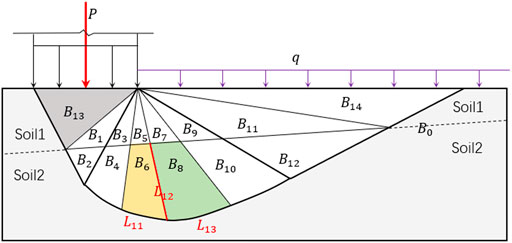
FIGURE 1. Improved rigid block division model.
The normal vector in the interface segment is defined as facilitating the establishment of an optimized mathematical model of the limit analysis upper-bound solution in the block division system. In addition, the inner normal vector’s calculation approach is briefly introduced below.
Any block
where
The internal normal vector of the
where
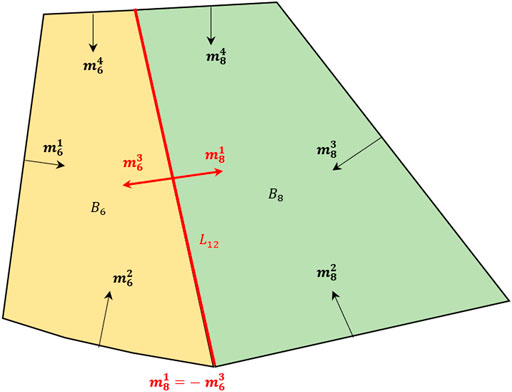
FIGURE 2. Definition of the normal vector in the interface segment.
2.2 Variable System
Variables involved in the optimization model of the foundation bearing capacity upper-bound solution consist of the ultimate bearing capacity (P), the velocity
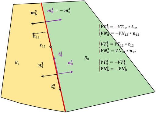
FIGURE 3. Approaches for representing the force on the interface used by two adjacent blocks in common.
In the block, the direction of the local coordinate system in
When
Obviously, the variables required by the variable system established by this method are less than the finite element of limit analysis. The main reasons are as follows: 1) the number of blocks after block discretization is less than the number of finite element elements; 2) the method in this paper is based on the block interface, the limit analysis finite element is based on nodes and needs to consider the situation of overlapping nodes, and the number of block interfaces is less than the number of nodes.
2.3 Constraint equations
According to the upper-bound theorem of limit analysis, the constraint equations comprise associated flow rule, velocity compatibility, and functional equilibrium equations.
2.3.1 Associated Flow Rule
The interface’s relative velocity must also conform to the associated flow rule, or the angle between the relative kinematic velocity and the interface should be equal to the internal angle
To better describe the characteristics of
Equation 5 can be rewritten as the following:
The upper-bound solution proposed by Chen et al. (2003), for example, assumed that the direction of
2.3.2 Velocity Compatibility Condition
Adjacent blocks should conform with the velocity compatibility condition, that is, a velocity triangle is made up by the relative velocity of the interface velocity and the velocity of two adjacent blocks and can be expressed mathematically as the following:
where
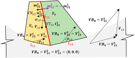
FIGURE 4. Velocity compatibility diagram.
2.3.3 Functional Equilibrium Equation
According to the associated flow law, the internal energy dissipation on the interface polygon
where
The gravity acting of the block is
where
The external work is
where
On this basis, a functional equilibrium equation for the whole slip mass can be obtained:
2.3.4 Other Constraints
To ensure that the blocks are not embedding, the relative normal velocity must also satisfy the constraint equation of Eq. 13:
2.4 Optimization Model
According to the upper-bound theorem, the foundation bearing capacity calculated by any failure mode satisfying the constraints is greater than the real foundation bearing capacity. The smaller the calculated foundation bearing capacity is, the closer it is to the real solution. Therefore, the objective function of the optimization model is to minimize the bearing capacity Eq. 14. The objective function Eqs 5, 6, 9, 14 as standard optimization models of constraint conditions are shown in Figure 5.
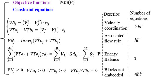
FIGURE 5. Optimization model.
2.5 Verification of Equation for Foundation Bearing Capacity
For foundations with agravic medium, Prandtl–Reissner assumes that the foundation bed is completely smooth with the failure mode (as shown in Figure 6A) and the calculation equation for ultimate bearing capacity given, using the characteristic approach:
where
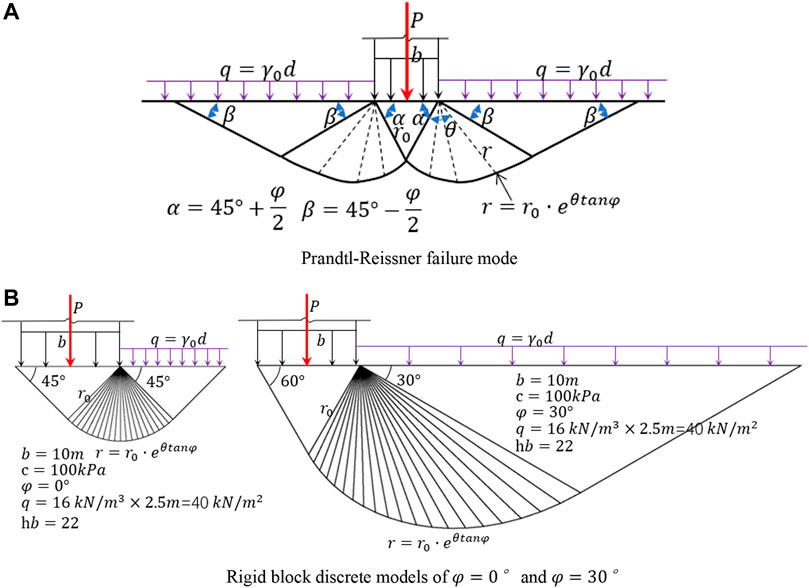
FIGURE 6. Prandtl–Reissner failure mode and rigid block discrete. (A) Prandtl–Reissner failure mode. (B) Rigid block discrete models of
As shown in Figure 6B, the rigid block discrete model is generated automatically according to the geometric relationship in the failure mode (when the friction angles in the soil mass are 0° and 30°). Then, an optimized mathematical model is established to obtain the ultimate bearing capacity of the foundation with an agravic medium under various parameters (Table 1). For the simple foundation with agravic medium, the calculation results obtained by the FLU proposed in this study are consistent with the theoretical solution, proving the rationality of the proposed approach.
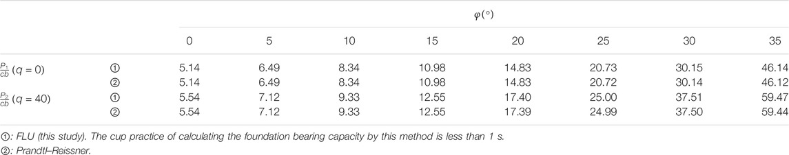
TABLE 1. Comparisons of ultimate bearing capacity and characteristic parameters under different internal friction angles.
3 Research on the Value Range of Slip Depth of Two-Layer Clay Foundation
The bearing capacity of the two-layer clay foundation is difficult to calculate. Many researchers have conducted analytical studies on it. To better present the advantages of the rigid block discrete in this study, slip modes similar to those used by Prandtl–Reissner and Terzaghi are for the discretion of rigid body, as shown in Figure 7. The slip depth coefficient
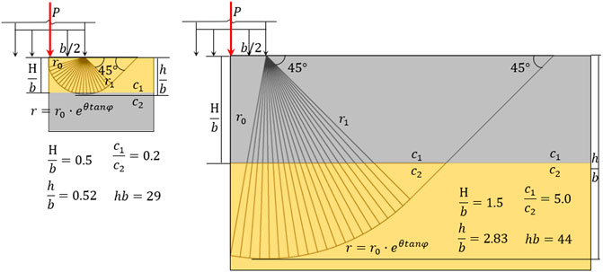
FIGURE 7. Calculation model of bearing capacity of the two-layer clay foundation.
To determine the value range of slip depth for two-layer clay foundations, the effect of slip depth
1) When
2) When
3) When
4) When
5) When
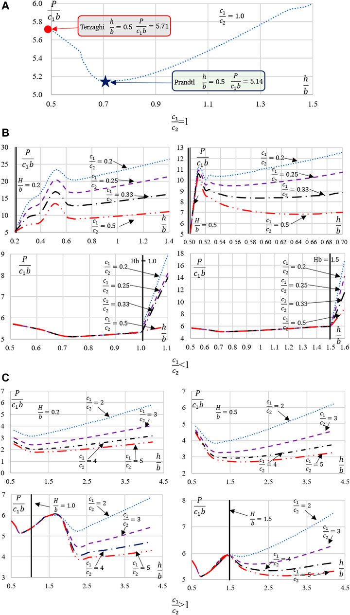
FIGURE 8.
According to the value range of
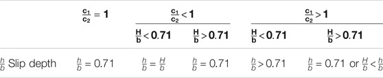
TABLE 2. Range of slip depth.
4 Optimized Calculation Method for the Bearing Capacity of Two-Layer Clay Foundation
Based on Table 2 and FLU, an optimized calculation approach for the bearing capacity of the two-layer clay foundation is proposed. The proposed approach first calculates the range of slip depth according to Table 2 and then obtains the final slip depth and foundation bearing capacity using the dichotomy in iteration. Figure 9 shows the specific process.
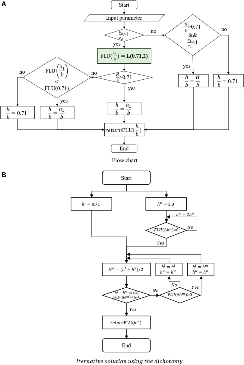
FIGURE 9. Optimized calculation approach for the bearing capacity of the two-layer clay foundation. (A) Flowchart, (B)
As shown in Figure 9, L (min, max) is an optimization model of an iterative solution using the dichotomy, where min is the minimum of the initial iteration interval, and max is the maximum of the initial iteration interval. FLU
Different calculation approaches of optimizing the bearing capacity of the two-layer clay foundation are used to calculate ultimate load under various combinations of
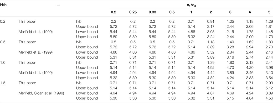
TABLE 3. Statistics of ultimate bearing capacity coefficient.
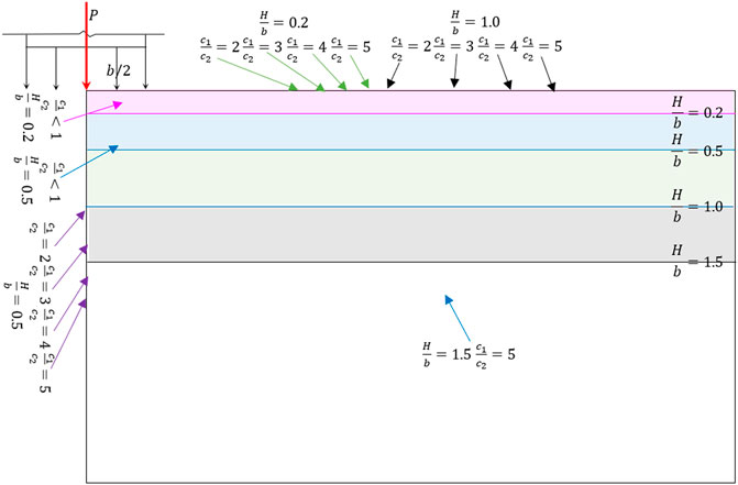
FIGURE 10. Typical failure modes.
5 Conclusion
1) An optimized mathematical model is first established based on a rigid block discrete system with the minimum bearing capacity as the objective function, block velocity as the main variable, and the satisfaction of velocity compatibility, associated flow rule, and functional equilibrium equations of an adjacent block as main constraints in the rigid block discrete system. Then, FLU is proposed after the upper-bound value of the bearing capacity of the foundation is obtained through an optimization solution.
2) The influence of slip depth
3) Based on the above results, an optimized calculation approach for the bearing capacity of the two-layer clay foundation is proposed by introducing an iterative solution using a dichotomy. Furthermore, the approach’s rationality is verified using a calculation example.
Data Availability Statement
The original contributions presented in the study are included in the article/Supplementary Material; further inquiries can be directed to the corresponding author.
Author Contributions
All authors listed have made a substantial, direct, and intellectual contribution to the work and approved it for publication.
Funding
This research was financially supported by the National Key R&D Program of China (No. 2018YFC0407000), the National Natural Science Foundation of China (Nos. 51809289, U1965204) and the IWHR Research and Development Support Program (Nos. GE0199A082021, GE110145B0022021). Research Project of China Three Gorges Corporation (Contract No. JG/19055J).
Conflict of Interest
XW and YF were employed by the company PowerChina Kunming Engineering Corporation Limited, and GZ was employed by the company Beijing Glory PKPM Technology Co., Ltd.
The remaining authors declare that the research was conducted in the absence of any commercial or financial relationships that could be construed as a potential conflict of interest.
Publisher’s Note
All claims expressed in this article are solely those of the authors and do not necessarily represent those of their affiliated organizations, or those of the publisher, the editors, and the reviewers. Any product that may be evaluated in this article, or claim that may be made by its manufacturer, is not guaranteed or endorsed by the publisher.
References
Alkhafaji, H., Imani, M., and Fahimifar, A. (2020). Ultimate Bearing Capacity of Rock Mass Foundations Subjected to Seepage Forces Using Modified Hoek–Brown Criterion. Rock Mech. Rock Eng. 53 (1), 251–268. doi:10.1007/s00603-019-01905-6
Chen, J., Yin, J.-H., and Lee, C. F. (2003). Upper Bound Limit Analysis of Slope Stability Using Rigid Finite Elements and Nonlinear Programming. Can. Geotech. J.40(4), 742–752.
Chen, W. F. (1975). Limit Analysis and Soil Plasticity. New York: Elsevier Scientific Publishing Company.
Davis, E. H., and Booker, J. R. (1974). The Effect of Increasing Strength with Depth on the Bearing Capacity of Clays : 14F, 6R. GEOTECHNIQUE, V23, N4, DEC. 1973, P551–563. Int. J. Rock Mech. Mining Sci. Geomechanics Abstr. 11 (3), 62. doi:10.1016/0148-9062(74)91688-x
Griffiths, D. V. (1982). “Computation of Bearing Capacity on Layered Soils,” in Proc., 4th Int. Conf. on Num Meth. In Geomechanics, Vol. 1, 163–170.
Huang, M., and Qin, H.-L. (2009). Upper-bound Multi-Rigid-Block Solutions for Bearing Capacity of Two-Layered Soils. Comput. Geotechnics 36 (3), 525–529. doi:10.1016/j.compgeo.2008.10.001
Lyamin, A. V., and Sloan, S. W. (2002). Upper Bound Limit Analysis Using Linear Finite Elements and Non-Linear Programming. Int. J. Numer. Anal. Methods Geomech. 26 (2), 181–216.
Merifield, R. S., Sloan, S. W., and Yu, H. S. (1999). Rigorous Plasticity Solutions for the Bearing Capacity of Two-Layered Clays. Géotechnique 49 (4), 471–490. doi:10.1680/geot.1999.49.4.471
Michalowski, R. L., and Lei, S. (1996). Bearing Capacity of Footings over Two-Layer Foundation Soils. J. Geotechnical Eng. 121 (5), 421–428. doi:10.1061/(asce)0733-9410(1995)121:5(421)
Osman, A. S. (2019). Upper Bound Solutions for the Shape Factors of Smooth Rectangular Footings on Frictional Materials. Comput. Geotechnics 115 (Nov), 103177. doi:10.1016/j.compgeo.2019.103177
Pham, Q. N., Ohtsuka, S., Isobe, K., and Fukumoto, Y. (2020). Limit Load Space of Rigid Footing under Eccentrically Inclined Load. Tokyo: Soils and Foundations.
Shamloo, S., and Imani, M. (2020). Upper Bound Solution for the Bearing Capacity of Rock Masses Considering the Embedment Depth. Ocean Eng. 218 (6), 108169. doi:10.1016/j.oceaneng.2020.108169
Terzaghi, K., and Peck, R. B. (1967). Soil Mechanics in Engineering Practice. second edition. New YorK: Wiley.
Wang, X. G., Lin, X. C., Sun, P., Li, X., and Ling, Y. Y. (2020). 2D Slope Stability Analysis Based on Pan's Maximum Principle. Bull. Eng. Geology. Environ. 79 (8). doi:10.1007/s10064-020-01840-9
Keywords: bearing capacity of foundation, limit analysis, upper bound solution, optimized mathematical model, two-layer clay foundation
Citation: Lin X-C, Zhang Q, Wang X, Feng Y and Zhu G (2022) Calculation Method for Optimizing the Bearing Capacity of Two-Layer Clay Foundation Based on Upper-Bound Limit Analysis. Front. Earth Sci. 9:825483. doi: 10.3389/feart.2021.825483
Received: 30 November 2021; Accepted: 27 December 2021;
Published: 16 February 2022.
Edited by:
Dongxing Wang, Wuhan University, ChinaCopyright © 2022 Lin, Zhang, Wang, Feng and Zhu. This is an open-access article distributed under the terms of the Creative Commons Attribution License (CC BY). The use, distribution or reproduction in other forums is permitted, provided the original author(s) and the copyright owner(s) are credited and that the original publication in this journal is cited, in accordance with accepted academic practice. No use, distribution or reproduction is permitted which does not comply with these terms.
*Correspondence: Qiang Zhang, emhhbmdxQGl3aHIuY29t