 Hui Zhuo1
 Xiaomeng Shi
95% of researchers rate our articles as excellent or good
Learn more about the work of our research integrity team to safeguard the quality of each article we publish.
Find out more
ORIGINAL RESEARCH article
Front. Earth Sci. , 05 January 2022
Sec. Geohazards and Georisks
Volume 9 - 2021 | https://doi.org/10.3389/feart.2021.814672
This article is part of the Research Topic Landslide Hazards in Alpine Region: Mechanics and Mitigation View all 23 articles
The segment lining is a new type of support structure for mining tunnels. The disturbance of coal excavation leads to the deformation of segment lining and has great hazards to the safety of the tunnels. Based on the tunnel boring machine (TBM) inclined tunnels in Xinjie mine, the ultimate span L0 of the rock beam on the top slab of the coal seam was calculated according to the bending (tension) damage theory. A numerical model was built to simulate the bottom area of the inclined tunnels. During the coal mining, the additional displacements and additional stresses of the segment lining were analyzed, and then the safety factors of the support structure were calculated. Finally, the width of the coal pillar to protect the inclined tunnels was determined. The results showed that the ultimate span of the rock beam on the top of the coal seam is 31.7 m, the deformation of the inclined tunnel has a fish-belly shape, and the deformation leads to the increase of maximum axial force and bending moment. For the inclined tunnels in Xinjie coalmine, a total width of 91.3 m of coal pillar must be reserved to keep the safety factor of the structure higher than 2.0 and prevent the inclined tunnels from the mining hazards.
The tunnel boring machine (TBM) has been widely used to build transportation and hydraulic tunnels, but its application in mining engineering is still limited (Liu et al., 2013). A TBM was first used in a coal mine in 1971 in Germany (Handewith 1983). In 1978, a 5.1-m-diameter TBM was used to excavate a 1.6-km-long decline for coal cliff collieries in the southern coalfields of New South Wales (White, 1978). In Germany, five sections of a total 13-km roadway tunnel in the Rheinland and Friedrich Heinrich collieries were excavated using a 6-m-diameter TBM between 1973 and 1980 (Boldt and Henneke, 1981). A TBM was used to excavate two drifts (762 and 933 m long) at Anglo American’s Grosvenor Mine in Moranbah, Queensland, Australia, in 2013 (Donnelly et al., 2014). Xinjie coalmine, Ordos, China, has planned to construct two inclined tunnels by TBM method, which will face technical difficulties because of the lack of relevant design experience (Yang et al., 2016). In the process of coal excavation, the movement of the overlying strata and the distribution of ground stress have a severe impact on the safety of the support structures, a problem that has not been encountered in the traditional design of segment lining support. Kulatilake et al. (2013) studied the stability of a tunnel in a deep coal mine in China. Xu et al. studied the mining-induced strata movement and roof behavior in an underground coal mine. Shi et al. (2016) and Shi et al. (2017) studied the influence of coal mining on the safety of the tunnels by using physical model test and Three-Dimension Distinct Element Code (3DEC) numerical simulation method. Qi et al. (2021) used 2D model tests and numerical simulation methods to optimize the design method of the width of the coal pillar to protect the tunnels. However, these studies mainly focus on the stress and deformation of the whole area caused by coal mining activities from the surface to the coal seam, rather than the most intense area at the bottom part of the tunnel near the coal seam, which has the largest additional stress and deformation. In this paper, the displacement and stress changes of the support structure are studied in detail for the most dangerous area, the safety factor is calculated, and the coal pillar calculation method is proposed.
Xinjie coalmine is located in the south-central part of Ordos city, the planned area of the mine is 737.8 km2, and the coal resource is 13,884.46 Mt. The planned TBM tunnels go down from the surface to a depth of 660 m with 6° inclined angle. With the increase of the depth, the load on the surrounding rock of the support structure increases, and the disturbance of coal excavation on the tunnels is the most serious, so the bottom area is considered to be the most dangerous area, as shown in Figure 1. The support structure is a segment lining with a thickness of 0.35 m and an outer radius of 3.65 m, using a staggered assembly structure. The material of the lining is C40 reinforced concrete. The tunnels cross coarse-grained sandstone, mudstone, and fine-grained sandstone up to 2-1 coal seam, and the lower part is mudstone, 2-2 coal seam, and sandy mudstone. The layer thickness and properties are shown in Table 1.
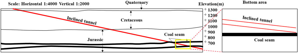
FIGURE 1. Overview of the TBM inclined shaft in Xinjie coalmine. TBM, tunnel boring machine.
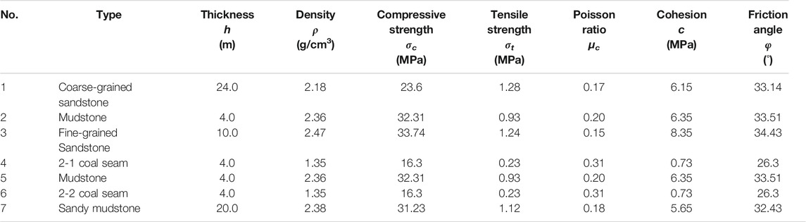
TABLE 1. Properties of the strata in the bottom region.
In the process of coal excavation, the coal seam roof collapse will induce overlying strata movement and stress redistribution, which leads to the additional stress and deformation of the lining structure (Liu et al., 1981; Yang et al., 2012). The coal excavation causes bending deformation of the roof strata, and both sides of the working face are coal seams to provide reaction force and bending moment to the roof structure, which can be regarded as a fixed beam structure at both ends. When the roof suspension span gradually increases, the roof will be the first to rupture above both sides of the working face, at which time the original beam structure constraints change, and the original fixed beam structure at both ends evolves into a simply supported beam structure as shown in Figure 2 (Zhao et al., 2009).
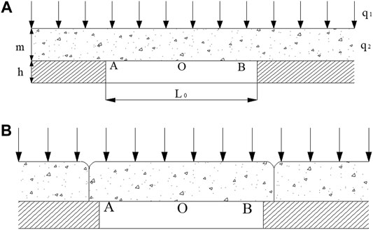
FIGURE 2. Supporting conditions and bending moments of rock beams. (A) Fixed beam structure at two ends. (B) Simple beam structure at two ends.
The rock beam in Figure 2 is subjected to the overlying ground load q1 and the self-weight q2. Based on the calculation method of the solid-supported beam at both ends of the beam, the bending moments at both ends (MA) and the middle (Mo) of the fixed beam (Figure 2A) can be obtained as
By comparing Eq. (Boldt and Henneke, 1981). and Eq. (Donnelly et al., 2014), it can be seen that the maximum bending moment occurs at the edge of the beam structure. In addition, since the rock is a brittle material, the tensile strength that it can withstand is low, so the maximum tensile strength criterion is used as the strength criterion for the destruction of the roof.
where σ0 is the tensile stress; W is the section modulus of the rock beam; MA is the section bending moment at the end of the rock beam; and [σt] is the maximum tensile stress of the roof rock.
When σ0 > [σt], the rock beam will rupture and form a simply supported beam structure (Figure 2B), and the bending moments are
Comparing the bending moments of the two types of beams, it can be found that the sum of the bending moments at both ends and the middle of the fixed beam is equal to the bending moment in the middle of the simply supported beam. So in the coal excavation process, the roof rock beam changes from the fixed beam to the simply supported beam, and the bending moment transfers from the two ends to the middle (Huang, 2002). Therefore, the mechanical process and conditions of the gradual development of the coal roof from bending to damage can be divided into two stages, as follows.
1) The working face advances forward, and when the rock beam overhanging span reaches the limit value L0, the tensile stress σA at the end of the beam is
If the overlying stratum has a hard layer, when the roof rock is bent and deformed, the overlying strata are delaminated and the rock beam is subjected to self-weight only, and the tensile stress σA at the end of the beam is damaged, as follows:
If the overlying stratum has a soft layer, it forms a combined rock beam with a hard bottom and a soft top, and the tensile stress σA at the end of the beam breaks is
where h is the thickness of the support layer of the roof and hi is the thickness of each layer of the overlying strata.
2) After the damage occurs at the end of the beam, the constraint condition gradually transforms from a super-stationary beam to a simply supported beam, and the bending moment gradually decreases, regardless of whether the bending moment in the middle of the beam increases. When the damage occurs in the middle of the beam, the bending moment is
At this stage, the central part of the roof will be cracked, and the rock beam will fall or reach the state of “pseudo plastic rock beam” (Zhai, 2002). The ultimate span of rock beam overhang L0 is
When bending damage occurs in a single rock formation, ∑hi = 0, the ultimate span is
Based on the geological survey data of Xinjie coalmine, the overlying ground pressure of the coal seam is 14.4 MPa, and the coal roof is fine-grained sandstone with a thickness of 10 m, density of 2.47 × 10³ kg/m3, and tensile strength of 1.24 MPa. According to Eq. (Shi et al., 2017), the ultimate span of the rock beam can be obtained as L0 = 31.7 m.
In order to study the effect of coal mining on the deformation and stress of the inclined shaft, numerical simulation was carried out using the finite element numerical analysis software MIDAS/GTS. As shown in Figure 3, the model dimensions are 140 × 84 × 70 m, and the width of the working face of the simulated coal seam excavation is 100 m. The stratigraphic parameters are shown in Table 1. The material of segment lining is C40 concrete. The Mohr–Coulomb criterion is used as the yield criterion, the load of the overlying strata is simulated by applying a loading of 14.4 MPa on the top, and the displacement boundary conditions are used around and at the bottom of the model with zero displacement perpendicular to the direction of the face.
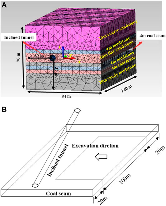
FIGURE 3. Numerical simulation model. (A) MIDAS/GTS model. (B) Mining process diagram.
MIDAS/GTS has the operation of “replicate grid group,” which is used to replicate each excavated seam at each step, set its elastic modulus to 0.01 kN/m2, “blunt” each section of the excavated seam, and “activate” the set replica “activation,” so as to simulate the bulk after a collapse. There is little influence when the coal seam is excavated far from the inclined tunnels. According to the calculated ultimate span L0 = 31.7 m, the change rules of the lining displacement, axial force, and bending moment with the advance distance of the working face are recorded at 32, 36, 40, and 44 m respectively.
The coal excavation causes the deformation of the segment lining. Considering the position of the coal seam, the deformation mainly happens in the X direction and the Z direction. Figure 4 shows the displacement at the top of the lining at each step in the X direction and the Z direction.
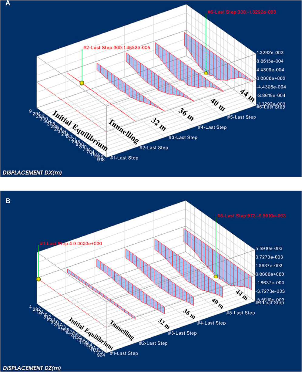
FIGURE 4. Deformation of the segment lining caused by mining (m). (A) In the X direction. (B) In the Z direction.
During the excavation of the coal seam, the vertical displacements of the monitoring sites gradually increase, and the rate accelerates, indicating that the strata are becoming more and more unstable. Along the axis direction, the displacement increases and then decreases, and the middle part has the largest displacement. The deformation of the tunnel has a fish-belly shape. The maximum vertical settlement was 5.59 mm when the excavation reached 44 m.
After the excavation of the coal seam, the additional stresses of the lining are expressed in the numerical software mainly as two results of axial force and bending moment. Figure 5 shows the bending moment in the X direction and the axial force in the Y direction for an excavation of 44 m. In each step, the maximum bending moment in the X direction and the axial force in the Y direction are shown in Table 2.
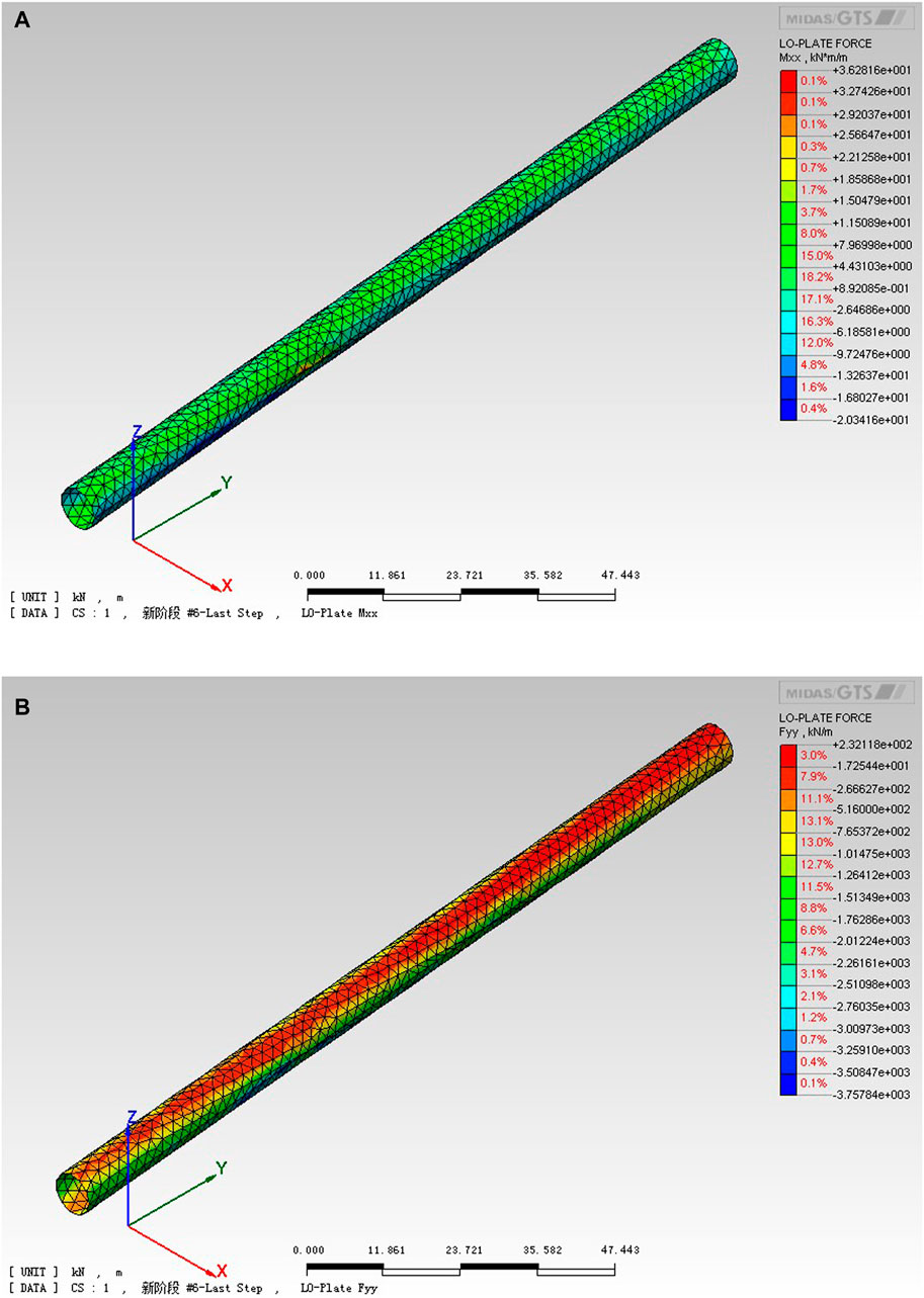
FIGURE 5. Bending moment in the X direction and axial force in the Y direction after excavating 44 m. (A) Bending moment in the X direction. (B) Axial force in the Y direction.
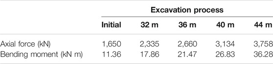
TABLE 2. Maximum axial force and bending moment.
For concrete segment lining structures, the safety factor could be calculated based on the maximum compressive stress in the compressed area and the design strength of concrete material (Vogel et al., 2000). According to the provisions in the Code for the Design of Concrete Structures, the maximum compressive stress and strength criterion for concrete eccentric compressive structures can be expressed by the Eq. (Vogel and Rast, 2000).
Converting the Eq. (Vogel and Rast, 2000), the safety factor is calculated as follows.
where K is the safety factor of structural bearing capacity, and K ≥ 2; fc is the design value of concrete axial compressive strength (MPa); b is the cross-sectional width of segment lining (m), and b = 1.5 m; h0 is the cross-sectional height of segment lining (m), and h0 = 0.35 m; γ0 is the important factor of structure, and γ0 = 1.1; γs is the load sub-factor, and γs = 1.35; N is the maximum axial force value (kN) in the lining; M is the maximum bending moment value (kN m) in the lining; and the design value of axial compressive strength of C40 concrete is fc = 19.1 MPa.
By substituting the maximum axial force and bending moment in Table 2 into Equation (Shi et al., 2017), the change of safety coefficient of the lining structure during the coal seam excavation can be calculated as shown in Table 3. Figure 6 shows the change rule of safety factor with the excavation distance. The empirical equation is as (Eq. 14).
where y is the safety factor and x is the excavation distance, m.
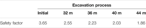
TABLE 3. Safety factor of the most dangerous section.
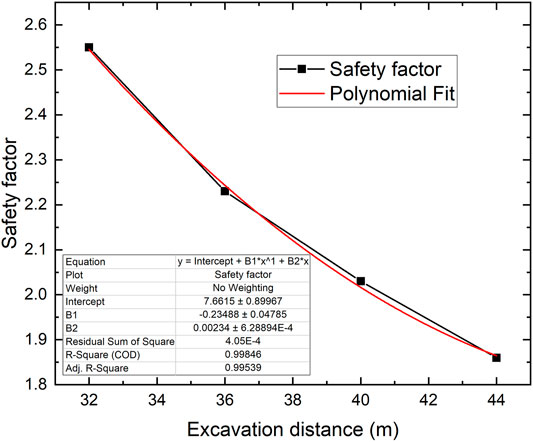
FIGURE 6. Change rule of safety factor of the segment lining with the excavation distance.
Xinjie coalmine has two inclined tunnels, and the distance between the two tunnels is 60 mm. According to the code for coal pillar design (Hu et al., 2017), the calculation of the width of the protective coal pillar is shown in Figure 7, and the width of the coal pillar L is
where a is the radius of the inclined tunnel and S1 is the width of the coal pillar protected on one side.
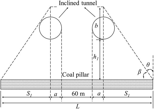
FIGURE 7. Schematic diagram of theoretical calculation.
In Figure 7, β is the angle of strata movement, φ is the angle of internal friction of the rock, and β = π/4 + φ/2. According to the geometric triangulation, it could be obtained as
And then
where φ = 34.4° is the internal friction angle for the fine-grained sandstone; h1 = 14.7 m is the maximum distance from the coal seam to the bottom of the inclined tunnel in the numerical model; a = 3.65 m is the outer diameter of the tunnel.
S1 is calculated to be 13.78 m, and substitute the parameters into Eq. 14, and the width of the coal pillar is calculated to be 94.86 mm.
In the numerical simulation, the safety factor when the concrete reaches the ultimate compressive strength is required to be greater than 2.0, so the reasonable excavation distance is 40 m, and the corresponding S1 is 12 mm. The width of the coal pillar for the two inclined tunnels is about 91.3 mm. The theoretical calculation results have high consistency with the numerical simulation, and the error is within a reasonable range, so it shows that the numerical simulation results are accurate and valid.
The segment lining is a new type of support structure for mine tunnels. In this paper, the behavior of the structure under the influence of coal excavation was studied using theoretical analysis and numerical simulation. It was proposed that the coal pillar with reasonable width must be reserved to prevent the tunnels from mining hazards. The main conclusions are as follows (Liu and Zhong, 1981; Handewith, 1983; Huang, 2002; Kulatilake et al., 2013; Liu et al., 2013; Shi et al., 2016; Hu et al., 2017; Qi et al., 2021; White, 1978; Zhai, 2002; Zhao et al., 2009; Yang et al., 2012; Yang and Xia, 2016):
1) According to the theory of bending (tension) damage, the limit span of rock beam at the top of the coal seam is L0 = 31.7 m for the coal seam in Xinjie coalmine.
2) During the excavation of the coal seam, the vertical displacement of the inclined tunnel gradually increases, and the rate accelerates with the excavation process, indicating that the excavation of the coal seam causes the stratum to be increasingly unstable. In the axial direction of the tunnel, the middle part has the largest displacement, so the deformation of the inclined tunnel has a fish-belly shape.
3) During the excavation of the coal seam, the deformation leads to the increase of the maximum axial force and bending moment of the structure. And the safety of the segment lining is gradually reduced.
4) The width of the single-side protection coal pillar of the inclined tunnel is 13.78 mm calculated according to the theory, while in the numerical simulation, the width is 12 mm when the safety factor is 2, which has a high consistency, and the error is within a reasonable range, so it shows that the numerical simulation results are accurate and effective.
5) For the inclined tunnels in Xinjie coalmine, a total width of 91.3 m of coal pillar must be reserved to keep the safety factor of the structure higher than 2 and prevent the inclined tunnels from mining hazards.
The raw data supporting the conclusions of this article will be made available by the authors, without undue reservation.
HZ formulated the problem studied in this paper and wrote the paper. DX contributed to the numerical simulation in this paper. JS contributed to the theoretical analysis in this paper. XS directed the research for this paper.
This work is supported by the Beijing Natural Science Foundation for Young Scientists (Grant No. 8214052), Open Fund of State Key Laboratory of Water Resource Protection and Utilization in Coal Mining (Grant No. GJNY-18-73.2), and National Science and Technology Support Program (2013BAB10B06).
Author HZ is employed by China Energy Investment Corporation.
The remaining authors declare that the research was conducted in the absence of any commercial or financial relationships that could be construed as a potential conflict of interest.
All claims expressed in this article are solely those of the authors and do not necessarily represent those of their affiliated organizations, or those of the publisher, the editors, and the reviewers. Any product that may be evaluated in this article, or claim that may be made by its manufacturer, is not guaranteed or endorsed by the publisher.
Boldt, H., and Henneke, J. (1981). Tunnel Boring under Coal Mining Conditions. 1981 Rapid Excavation and Tunneling Conference, 722–737.
Donnelly, C., Rammage, G., and Donghi, M. (2014). The Australasian Institute of Mining and Metallurgy & Mine Managers Association of Australia, In Alternative Excavation Methods in Undeground Coal Mining. 14th Coal Operators’ Conference. Australia: University of Wollongong, 216–223.
Handewith, H. J. (1983). TBM Tunnels in the Western Hemisphere; an Overview Tunneling. Technology Newsl. 41, 1–8.
Hu, B. N., Zhang, H. X., and Shen, B. H. (2017). Code for Coal Pillar Retention and Pressed Coal Mining in Buildings, Water Bodies, Railways and Main Shafts. Beijing: China Coal Industry Publishing House.
Huang, Q. X. (2002). Ground Pressure Behavior and Definition of Shallow Seams. Chin. J. Rock Mech. Eng. 8, 1174–1177. doi:10.3321/j.issn:1000-6915.2002.08.014
Kulatilake, P. H. S. W., Wu, Q., Yu, Z., and Jiang, F. (2013). Investigation of Stability of a Tunnel in a Deep Coal Mine in China. Int. J. Mining Sci. Technology 23, 579–589. doi:10.1016/j.ijmst.2013.07.018
Liu, Q. S., Shi, K., and Huang, X. (2013). Feasibility of Application of TBM in Construction of Deep Coal Mine and its Key Scientific Problems. J. Mining Saf. Eng. 30 (5), 633–641.
Liu, T. Q., and Zhong, W. L. (1981). Law of Surface Movement and Overburden Failure in Coal Mine and its Application. Beijing: China Coal Industry Publishing House.
Qi, Y., Liu, B., Tannant, D., Zheng, W., Wang, Y., and Shi, X. (2021). Protective Coal Pillar Design for Segmental Lining-Supported TBM Mine Tunnels Using Physical Model Tests. Geomech. Geophys. Geo-energ. Geo-resour. 7, 21. doi:10.1007/s40948-021-00221-0
Shi, X.-m., Liu, B.-g., Tannant, D., and Qi, Y. (2017). Influence of Consolidation Settlement on the Stability of Inclined TBM Tunnels in a Coal Mine. Tunnelling Underground Space Technology 69, 64–71. doi:10.1016/j.tust.2017.06.013
Shi, X. M., Liu, B. G., Li, T., and Du, X., (2016). Stress and Deformation Analysis of Shield Incline Shafts Segment Due to Dewater Settlement of Aquifer. Chin. J. Rock Mech. Eng. 35 (S1), 3057–3063. doi:10.13722/j.cnki.jrme.2014.1717
Vogel, M., and Rast, H. P. (2000). AlpTransit-safety in Construction as a challenge: Health and Safety Aspects in Very Deep Tunnel Construction. Tunnelling Underground Space Technology 15 (4), 481–484. doi:10.1016/S0886-7798(01)00018-9
White, S. B. (1978). The Use of a Tunnel Boring Machine on a Coal Mine Decline in Australian Tunnelling Conference. 3rd edition (Sydney, NSW, 66–70.
Xu, T., Yang, T.-h., Chen, C.-f., Liu, H.-l., and Yu, Q.-l. (2015). Mining Induced Strata Movement and Roof Behavior in Underground Coal Mine. Geomech. Geophys. Geo-energ. Geo-resour. 1, 79–89. doi:10.1007/s40948-015-0010-2
Yang, J. Z., and Xia, G. B. (2016). Key Technology of TBM Construction for Long Distance Inclined Shaft in Coalmine. Beijing: China Railway Publishing House.
Yang, Y. G., Zhang, H. Y., and Gan, Q. C. (2012). Study on Surrounding Rock Deformation Mechanism and Supporting Technology along Goaf Roadway with High Ground Pressure in Deep Wells. Coal Eng. 6, 76–79. doi:10.3969/j.issn.1001-8972.2012.12.028
Zhai, X. X. (2002). Simulation Testing Study on Roof Strata Displacement of Top-Coal Caving Face. Chin. J. Rock Mech. Eng. 21 (11), 1667–1671. doi:10.3321/j.issn:1000-6915.2002.11.018
Keywords: mining hazards, segment lining, mining excavation, numerical simulation, safety factor
Citation: Zhuo H, Xie D, Sun J and Shi X (2022) Mining Hazards to the Safety of Segment Lining for Tunnel Boring Machine Inclined Tunnels. Front. Earth Sci. 9:814672. doi: 10.3389/feart.2021.814672
Received: 14 November 2021; Accepted: 26 November 2021;
Published: 05 January 2022.
Edited by:
Xuewei Liu, Institute of Rock and Soil Mechanics (CAS), ChinaReviewed by:
Zhizhen Zhang, China University of Mining and Technology, ChinaCopyright © 2022 Zhuo, Xie, Sun and Shi. This is an open-access article distributed under the terms of the Creative Commons Attribution License (CC BY). The use, distribution or reproduction in other forums is permitted, provided the original author(s) and the copyright owner(s) are credited and that the original publication in this journal is cited, in accordance with accepted academic practice. No use, distribution or reproduction is permitted which does not comply with these terms.
*Correspondence: Xiaomeng Shi, c2hpeG1AYmp0dS5lZHUuY24=
Disclaimer: All claims expressed in this article are solely those of the authors and do not necessarily represent those of their affiliated organizations, or those of the publisher, the editors and the reviewers. Any product that may be evaluated in this article or claim that may be made by its manufacturer is not guaranteed or endorsed by the publisher.
Research integrity at Frontiers
Learn more about the work of our research integrity team to safeguard the quality of each article we publish.