 Hang Yu1
 Chen-hui Zhu
- 1School of Transportation and Civil Engineering, Nantong University, Nantong, China
- 2Water Project Management of Nantong-Lvsi Canal, Nantong, China
The dilatancy equation, which describes the plastic strain increment ratio and its dependence on the stress state, is an important component of the elastoplastic constitutive model of geotechnical materials. In order to reveal their differences of the dilatancy value determined by the total volume strain increment ratio and the real value of lean cemented sand and gravel (LCSG) materials, in this study, a series of triaxial compression tests, equiaxial loading and unloading tests, and triaxial loading and unloading tests are conducted under different cement contents and confining pressures. The results reveal that hysteretic loops appear in the stress–strain curves of equiaxial loading and unloading tests, and triaxial loading and unloading tests and that the elastic strain is an important component of the total strain. The hysteretic loop size increases with an increase in the stress level or consolidation stress, whereas the shape remains unchanged. Furthermore, with an increase in the cement content, the dilatancy value determined by the total volume strain increment ratio becomes smaller than that determined by the plastic strain increment ratio, and the influence of the elastic deformation cannot be ignored. Thus, in practical engineering scenarios, especially in the calculation of LCSG dam structures, the dilatancy equation of LCSG materials should be expressed by the plastic strain increment ratio, rather than the total volume strain increment rati.
Introduction
Lean cemented sand and gravel (LCSG) material is a new type of artificial synthetic material formed by adding a small amount of cemented agent and water to natural sand, gravel, waste materials or broken stone, and other materials obtained from riverbeds or mountainous areas near a construction project. Because LCSG materials can realize the complete utilization of environmental waste materials, they provide comprehensive advantages in terms of economics, environmental protection, energy conservation, construction efficiency, and safety. LCSG materials with a cement content exceeding 60 kg/m3 are often used for building LCSG dams, cofferdams, or embankments (Londe and Lino, 1992; Jia et al., 2016). Thus far, more than 40 LCSG dams and cofferdams have been built worldwide (Londe and Lino, 1992; Jia et al., 2016). The construction height of these, as well as other LCSG structures, has gradually increased over time, with the maximum height of some dams even reaching 100 m. Such LCSG materials exhibit advantages in terms of dam safety, cost reduction, and environmental protection; moreover, they can simplify the construction process and shorten the construction period, thus reducing the associated costs. In contrast, LCSG materials with a cement content below 60 kg/m3 are often used in certain slope and foundation reinforcement projects. However, at present, the application of LCSG material is still in the preliminary stage of exploration, and its applicability in engineering remains to be further investigated. For the widespread application of LCSG material in dam construction and foundation, as well as slope reinforcement engineering, its mechanical properties must be thoroughly elucidated and controlled.
The mechanical properties of LCSG material and its related materials are typically studied by conducting mechanical material tests. Sun et al. (Sun, 2016) and Jia et al. (Feng, 2013) conducted experiments on the characteristics of LCSG materials to investigate their compressive and flexural strengths, and obtained reference values for the cement content, sand content, water-to-binder ratio, aggregate gradation, and other material components of LCSG material. Jia et al. (Wang et al., 2018) performed compression and splitting tests on LCSG material reinforced with a small amount of fiber, and revealed that the fiber effectively improved the ductility, compression, and tensile strength of LCSG material.
The studies cited above systematically analyzed the strength characteristics and deformation moduli of LCSG material under the condition of no lateral pressure. However, there is a need to study in-depth the mechanical properties of LCSG material and its similar materials and to analyze for practical engineering applications (such as dam engineering and reinforcement engineering) its structural performance under different stress states. Consequently, several scholars have employed triaxial compression tests to determine the effect of different confining pressures, material compositions, and curing ages on the mechanical properties of the materials. For example, to analyze the variation in the mechanical properties of LCSG materials subjected to various curing ages and confining pressures (0–800 kPa), such as peak strength and initial modulus, Wu et al. (Wu et al., 2011) conducted triaxial shear tests. Younes et al. (Amini and Hamidi, 2014; Fu et al., 2015; Yang et al., 2018a; Yang et al., 2019) successively conducted triaxial shear tests on cemented gravel with different cement contents under varying confining pressures (0–1,500 kPa). They analyzed how the stress–strain curves varied as a function of the confining pressure and cement content.
Meanwhile, the mechanical properties and constitutive model under different confining pressures and cemented contents have also been investigated. Based on the results of large-scale static triaxial compression tests conducted on modified and unmodified coarse-grained soils, Chen et al. (Liu et al., 2019) found that the modified soil exhibited effectively improved compressive strength, cohesion, and elastic modulus as compared to the unmodified soil. Additionally, the modified soil exhibited a reduction in the maximum volume compression strain as well as in the corresponding axial strain and axial strain at failure, while demonstrating significantly altered dilatancy characteristics. Yang et al. (Yang et al., 2018b) conducted triaxial unloading–reloading tests on high polymer rockfill material to investigate its mechanical properties related to unloading and reloading, as well as the changes in the rebound modulus with respect to the confining pressure and stress level. To effectively strengthen retaining walls, embankments, slopes, and clay liners, Kong et al. (Kong et al., 2018) investigated the influence of different fiber contents on the strength, deformation, and dilation characteristics of these systems by conducting conventional triaxial compression tests of fine sand reinforced with polypropylene fiber under different confining pressures. Zeng et al. (Jin et al., 2017) conducted large-scale triaxial tests on cemented soil–rock mixtures under different lump contents and geometries to investigate the changes in their strength characteristics, deformation modulus, and other mechanical indices. Xu et al. (Xu et al., 2020) conducted triaxial compression tests to examine the influences of cement content, curing age, and confining pressure on the strength and deformation characteristics of cemented tailing backfill. Yun et al. (Yu et al., 2021) investigated the evolution characteristics of the shear band in soil-rock mixture by Granular discrete element simulation. Based on the results of the aforementioned uniaxial and triaxial tests, various engineering structures have been constructed.
A reasonable dilatancy equation is key to the constitutive model of geomaterials. Since the introduction of the dilatancy equation by Rowe (Rowe, 1962), the dilatancy problem has been extensively researched worldwide. Some experts have directly adopted or modified the Rowe dilatancy equation to reflect the dilatancy characteristics of their geotechnical materials (Liu et al., 2008; Jiang et al., 2014; Wang et al., 2015; Wei et al., 2016; Yao et al., 2018). For example, Yao et al. (Yao et al., 2018) modified the dilatancy equation of the Cambridge model to reflect the dilatancy characteristics of sand and other materials. Some experts have also established dilatancy equations according to the volumetric strain–axial strain fitting relation. Although these dilatancy equations exhibit different forms, all of them can describe the dilatancy characteristics of geotechnical materials to some extent. Thus far, the studies conducted on the dilatancy of LCSG materials have been based on the dilatancy of coarse-grained soil; that is, the ratio between the variations in the volume strain and shear strain is directly expressed. In the aforementioned constitutive LCSG models (Cai et al., 2016; Wei et al., 2019), although various forms of dilatancy equations have been introduced, most only consider the relation between the total volumetric strain and the axial strain. The previous studies were based on the following concept: When constructing a constitutive model using loose particles, such as those in coarse-grained soil, the ratio of the total volumetric strain to the axial strain can be directly used as the dilatancy ratio. However, it remains unclear whether the plastic strain increment ratio of LCSG material, which is a cementitious granular material formed by adding a cementitious agent to rockfill, is close to or the same as the total strain increment ratio. A thorough understanding of the dilatancy properties of LCSG materials in the unloading and reloading path is necessary, in order to improve the reliability of the stress and deformation results for the unloading and reloading processes of LCSG dams and other project.
Therefore, in this study, a series of triaxial compression tests, equiaxial loading and unloading tests, and triaxial loading and unloading tests of LCSG material are conducted under various confining pressures. The relation between the plastic volumetric strain and axial strain is determined and analyzed, and the variation rule of the dilatancy ratio of LCSG material subjected to different stress states is explored using different cement contents. Whether the dilatancy model of LCSG material must be expressed in terms of the plastic volumetric strain to axial strain ratio is also confirmed.
Dilatancy Equation
According to geotechnical plasticity theory, volumetric strain is not only related to normal stress, it is also generated by shear stress. This property of a material is called dilatancy. The dilatancy equation is defined as a function of the dilatancy ratio dg which can be expressed by the following formula.
Most studies conducted on geotechnical materials ignore the influence of elastic deformation and consider the dilatancy ratio to involve only the total strain. That is
Where
It is not clear whether the dilatancy characteristics of LCSG materials can be directly applied to the above formula. To determine whether the dilatancy value of the material can only be expressed by the ratio of the plastic volume strain to the shear strain, it is necessary to compare and analyze the results obtained from Eqs 1, 2.
The elastic volumetric strain of LCSG materials can be defined as
Where K is the bulk modulus.
Materials and Methods
We studied the dilatancy behavior of LCSG materials under three different cement contents: 20 kg/m3, which is used for foundation and slope reinforcement engineering; 60 and 100 kg/m3, which are commonly used for building LCSG dams.
Materials and Test Specimens
In accordance with the “SL678-2014 Technical Guidelines for Damming with Cemented Granule Material,” (SL678-2014 Technical Guide Line for Cemented Granular Material Dams Particles, 2014) the cemented agent used for the LCSG materials was Hailuo PC 32.5 ordinary Portland cement, the water–binder ratio was set to 1.0, the fine aggregate was the medium and coarse sand purchased from the Nanjing market, and the coarse aggregate was broken stone collected from the suburbs of Nanjing. In the LCSG material used for the triaxial test, the sand and broken stone contents were 20 and 80%, respectively, of the total fine and coarse aggregate materials. The sand and broken stone were graded as shown in Figure 1, and the dry density of the aggregate was 2,130 kg/m3. The mixing ratios of each group of LCSG specimens are listed in Table 1.
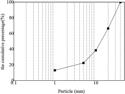
FIGURE 1. Aggregate grading curve.
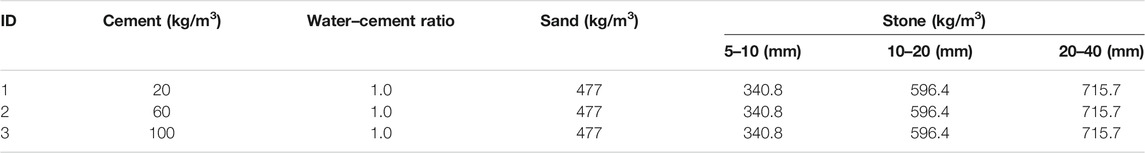
TABLE 1. Details of the test specimens.
Test Procedure
The triaxial test specimens of LCSG material were fabricated using a mold of diameter 300 mm and height 700 mm. The preparation process can be described as follows. 1) The aggregate was screened according to the aggregate grading requirements; 2) the contents of the material components of the LCSG specimen, including the cementitious agent, coarse and fine aggregates, water, and other materials, were mixed evenly; 3) the LCSG material was divided into five layers and loaded into a cylindrical mold, and each layer was crushed and vibrated to form a specimen (Figure 2B); and 4) the formed specimens were cured for 28 days. The process has been described by Yang et al. (Yang et al., 2018a; Yang et al., 2019)
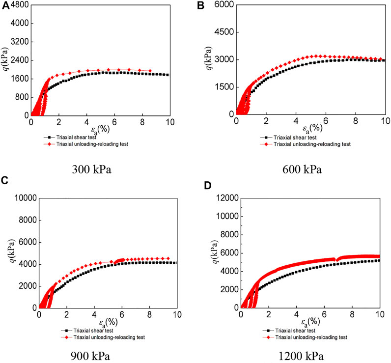
FIGURE 2. Stress–strain curves of LCSG material with cemented content of 20 kg/m3 under different confining pressures. (A) 300 kPa (B) 600 kPa (C) 900 kPa (D) 1,200 kPa.
A TYD-1500 triaxial tester located in the geotechnical laboratory of the Nanjing Hydraulic Research Institute was used. Using this instrument and in accordance with the “geotechnical test regulations (SL237-1999),” (SL237-1999 Specification of Soil Test, 1999) large-scale triaxial drainage shear test, triaxial equiaxial loading and unloading test, and axial loading and unloading test were conducted on the LCSG materials.
The specimens for the triaxial compression tests were divided into three groups according to the three cement contents. The specimens were saturated and consolidated under confining pressures of 300, 600, 900, and 1,200 kPa. Then, triaxial drainage shear tests were conducted, which were terminated when either the axial strain reached 15% or the samples were completely destroyed.
During the triaxial unloading–reloading tests, the specimens were attached to the testing instrument using a rubber film, and the confining pressure was applied after water was injected into the sample to completely saturate it. First, conventional triaxial consolidation and drainage shear tests were conducted. After the stress reached the specified level, it was stabilized for 2 min; then, an unloading test was conducted. Next, the axial stress was reduced to zero and stabilized for 2 min; then, a reloading test was conducted. The unloading stress levels in this test were set to 0.25, 0.65, and 0.8. The stress unloading–reloading rate in the entire testing process, which was unloaded three times, was set to 1 mm/min, as shown in Table 2.
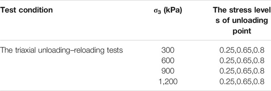
TABLE 2. Multistage unloading–reloading sequences in the triaxial tests of LCSG materials with cement contents of 20, 60, and 100 kg/m3.
The equidirectional loading and unloading tests of the LCSG materials with 20, 60, and 100 kg/m3 cement contents were performed after the various curing periods. The specimens were lifted onto the triaxial tester and saturated using the hydrostatic head method. After saturation, 100 kPa pressure was applied to the specimens in all directions for consolidation. The load was continuously increased until a predetermined stress value was reached, followed by unloading to 100 kPa. Then, loading was performed again. In this test, the unloading stress was set as 300, 600, 900, and 1,200 kPa.
Results and Discussion
Triaxial Compression Tests
Figures 2–4 shows the stress–strain curves of the LCSG samples subjected to triaxial compression tests under different cement contents of 20, 60, and 100 kg/m3, as well as those of the LCSG samples subjected to triaxial loading and unloading tests. The figure shows that the loading curve of the loaded LCSG sample subjected to the unloading–reloading triaxial test under the three different cement contents is consistent with the stress–strain curve of the sample subjected to the full-loading triaxial test, which is a typical triaxial test (Yang et al., 2018a; Yang et al., 2019), indicating the reliability of the test results. However, the unloading curves of the LCSG specimens are inconsistent with the reloading curves, and hysteretic loops are formed in the process of unloading and reloading. All the hysteretic loops formed are crescent-shaped; in contrast, the hysteretic loops of coarse-grained soil without a gelling agent are elliptical (Zhu et al., 2011; Chu et al., 2012). This is primarily because coarse-grained soil exhibits plastic deformation only during unloading and reloading. In the LCSG material, in addition to plastic deformation, the binder imparts certain viscosity to the aggregated particles. With an increase in the stress level, the shape of the hysteresis loops remains unchanged; however, their size gradually increases. The LCSG materials with cement contents of 100 and 60 kg/m3 exhibit highly crescent-shaped hysteresis curves with a smaller width than that of the LCSG material with a cement content of 20 kg/m3. In addition, the shear strength of the LCSG specimen in the unloading and reloading path is higher than that of the specimen in the conventional triaxial loading path under different cement contents, which is similar to the shear strength of coarsely grained soil.
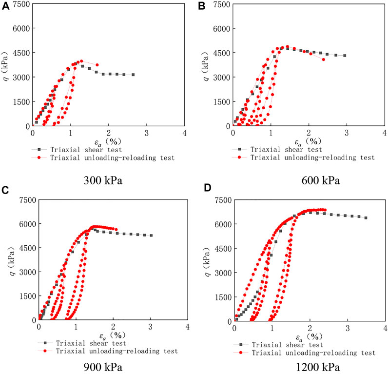
FIGURE 3. Stress–strain curves of LCSG material with cemented content of 60 kg/m3 under different confining pressures. (A) 300 kPa (B) 600 kPa (C) 900 kPa (D) 1,200 kPa.
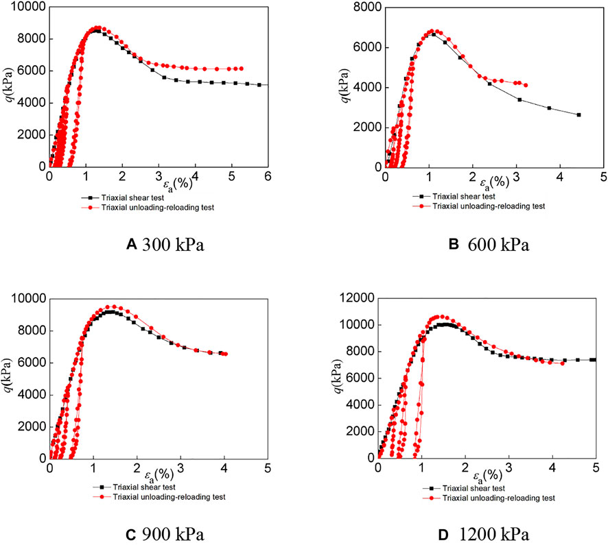
FIGURE 4. Stress–strain curves of LCSG material with cemented content of 100 kg/m3 under different confining pressures. (A) 300 kPa (B) 600 kPa (C) 900 kPa (D) 1,200 kPa.
Figures 5–7 shows the volumetric strain curves of the LCSG samples subjected to triaxial compression and loading and unloading tests under the different cement contents. Here, the value of the slope at each point on the volumetric strain curves under different cement contents and confining pressure changes from positive to negative, which shows that the dilatancy of the LCSG specimens first shrinks and then dilates. A comparison of the compression test results with the loading and unloading test results indicates that the relation between the volume strain and axial strain of LCSG material subjected to compression is similar to that of the sample subjected to unloading and reloading. Moreover, the dilatancy of LCSG material reflected by the loading and unloading tests occurs at the same position as that in the triaxial loading test. For the same cement content, the lower the confining pressure is, the more easily is the shear dilatancy of the LCSG material that can occur under the triaxial compression, unloading, and reloading conditions. The dilatancy reflected by these tests is larger under the condition of low cement content or low confining pressure.
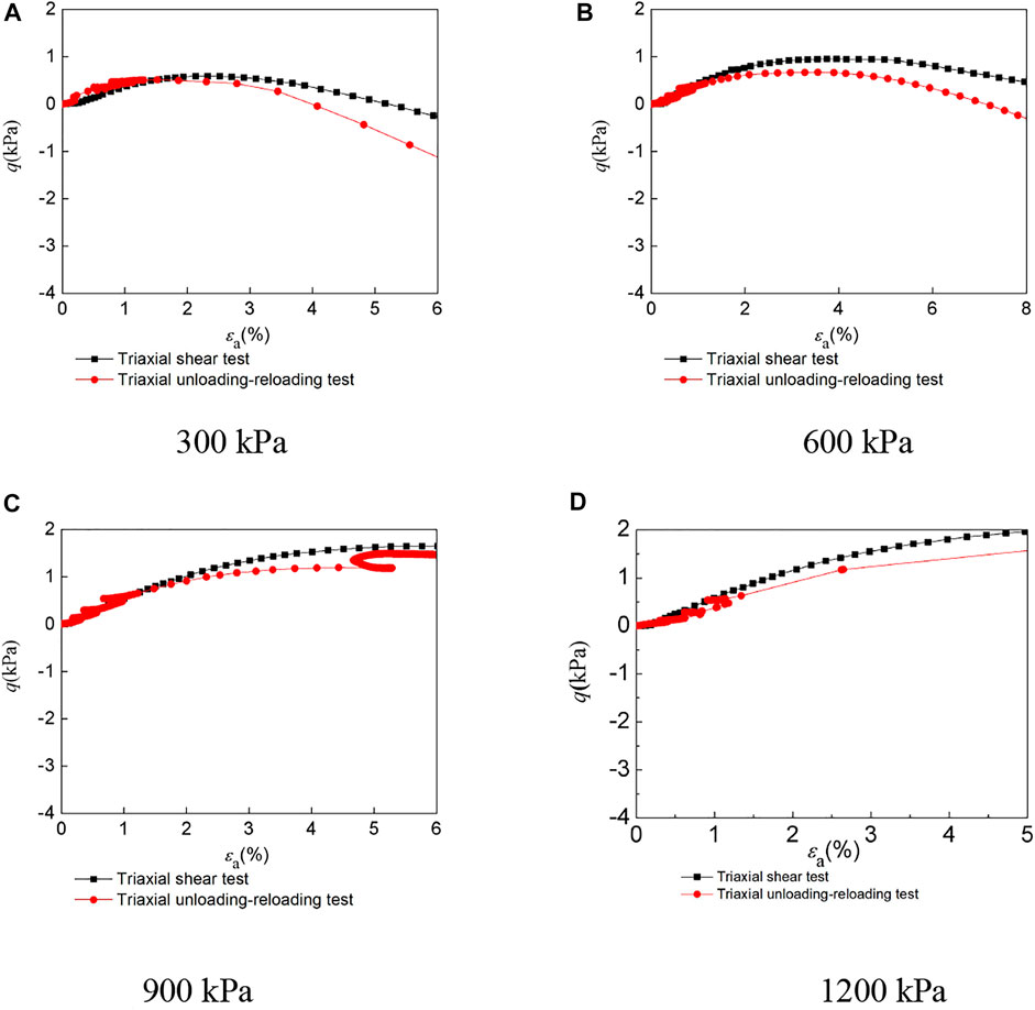
FIGURE 5. Volumetric strain–axial strain curves of LCSG material with cemented content of 20kg/m3 under different confining pressures. (A) 300 kPa (B) 600 kPa (C) 900 kPa (D) 1,200 kPa.
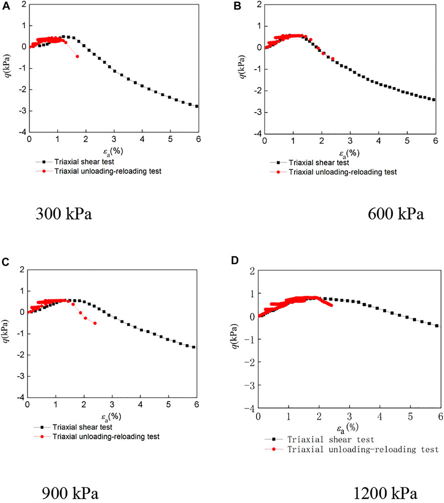
FIGURE 6. Volumetric strain–axial strain curves of LCSG material with cemented content of 60 kg/m3 under different confining pressures. (A) 300 kPa (B) 600 kPa (C) 900 kPa (D) 1,200 kPa.
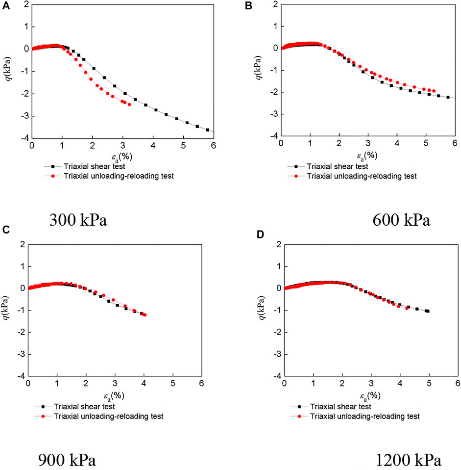
FIGURE 7. Volumetric strain–axial strain curves of LCSG material with cemented content of 100 kg/m3 under different confining pressures. (A) 300 kPa (B) 600 kPa (C) 900 kPa (D) 1,200 kPa.
At a high cement content, the LCSG material can easily form a stronger whole. At low pressure, the damaged particles at the cemented site are easy to roll over, showing a slight shearing contraction first, and then shearing expansion. Under high confining pressure, the binding force of the damaged particles in the cementation area increases, and the roll over is blocked. Meanwhile, the particles slide and squeeze to fill the pores, and the macroscopic behavior is shearing contraction first and then slight dilatancy. In contrast, at a low cement content, the LCSG material can easily become compact in the shear process, which is mainly manifested as shear shrinkage in the entire test process. When the dosage of the cemented agent is 20 or 60 kg/m3, the volume shrinkage of the LCSG material occurs when unloading under different confining pressures. In the unloading process, the sample with a gelling agent dosage of 100 kg/m3 expands under a confining pressure of 300 kPa and shrinks as the pressure is increased.
The dilatancy characteristics of LCSG material have been reflected by the ratio of the increment of the volumetric strain and axial strain in test curves of the LCSG material above and from other scholars. However, they have not been reflected by the ratio of the increment of the plastic volumetric strain and plastic axial strain, and its accuracy remains to be determined. Therefore, it is necessary to try to determine its plastic strain curve.
To express the dilatancy behavior of LCSG material in terms of the plastic strain ratio, the elastic axial strain and the volumetric strain must be known.
According to some scholars, the elastic modulus can be directly expressed as the unloading modulus, and the elastic tangential modulus can determine the elastic axial strain. The unloading and reloading curves of the LCSG samples with the different cement contents can be divided into three stages: initial curve, intermediate linear curve, and end curve. In terms of stress, the initial curve and end curve stages account for less than 10% of the total curve; in terms of strain, they account for less than 20% of the total curve. Here, the elastic modulus can be directly expressed by the average slope of the middle linear curve, between the unloading and loading of the LCSG specimens, at different stress levels. The elastic modulus of LCSG material with different cemented contents increases nonlinearly with the confining pressure; this relation is consistent with the initial modulus expression provided by Yang et al. (Yang et al., 2019). That is
where Kur is the elastic modulus when the confining pressure is zero, and n is the increasing exponent.
Isodirectional Loading and Unloading Tests
To reflect more accurately the dilatancy properties of LCSG material, in addition to determining the plastic shear strain, the plastic volumetric strain should be determined separately, and the elasticity volumetric strain determined by the bulk modulus is a crucial step. In this study, the bulk modulus was analyzed by combining the triaxial unloading with the loading test.
Figure 8 shows the triaxial equiaxial loading and unloading test curves of the LCSG material specimens. Here, similar to the triaxial loading and unloading test results, an elastic aftereffect exists in the isotropic loading and unloading tests. Additionally, hysteretic loops are formed after unloading and reloading. Because coarse-grained soil exhibits plastic deformation under equiaxial loading and unloading tests, and the binder imparts certain viscosity to the aggregated particles, as the stress applied at the unloading point is increased, the size of the resulting hysteretic loop gradually increases without any change in the shape, and the strain value at the center of the hysteretic loop increases. This indicates that, in the isodirectional loading and unloading tests, the slope of the secant line of the unloading curve of LCSG material bears little relation to the stress state.
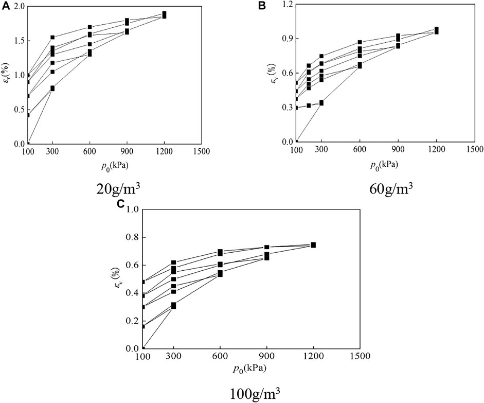
FIGURE 8. The triaxial equiaxial loading and unloading test curves of LCSG material. (A) 20 g/m3 (B) 60 g/m3 (C) 100 g/m3.
The elastic shear strain can be determined by examining the elastic shear modulus using Eq. 4, and the elastomer strain can be obtained by conducting isotropic loading and unloading tests. The elastomer strain can be obtained as
Figure 9 shows the relation between the volumetric strain εv and ln (1 + p/Pa) for LCSG material with cement contents of 20, 60, and 100 kg/m3. The elastic volumetric strain is the volumetric strain of the spring back component of this system, and its relation with ln (1 + p/Pa) can be expressed as follows:
where kt is the slope of the secant line of the hysteresis loop curve.
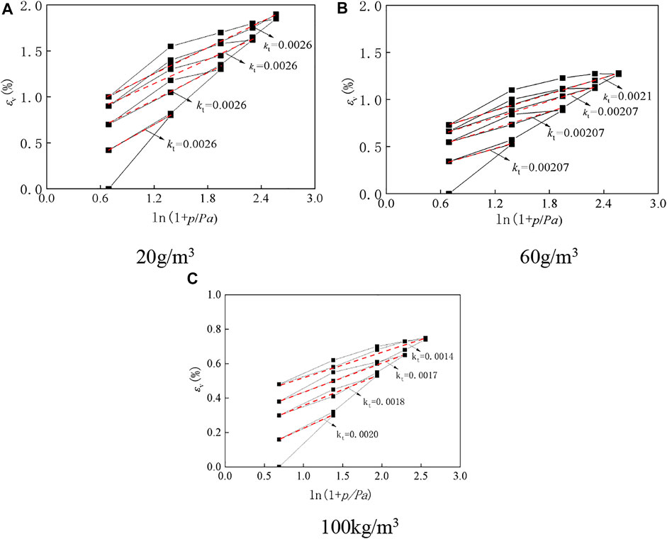
FIGURE 9. The relation between εv and ln (1 + p/Pa). (A) 20 g/m3 (B) 60 g/m3 (C) 100 g/m3.
Dilatancy Properties
Figure 10 shows the plastic volumetric strain and shear strain of LCSG material, according to Eqs 1, 2.
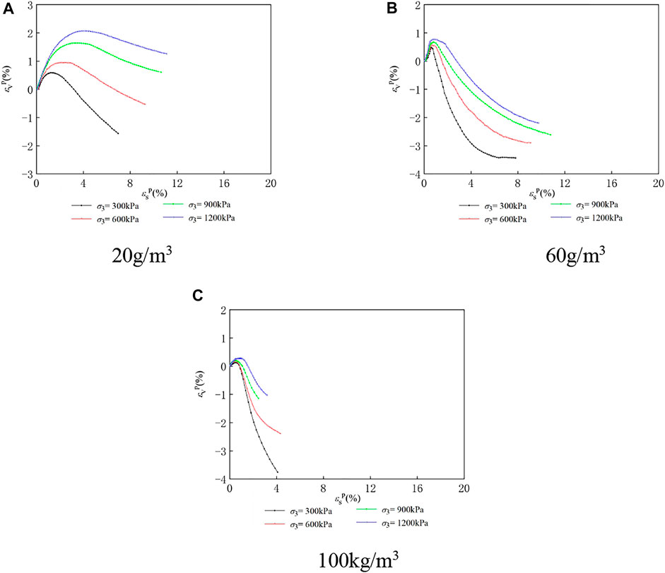
FIGURE 10. The plastic volumetric strain and shear strain of LCSG material. (A) 20 g/m3 (B) 60 g/m3 (C) 100 g/m3.
As shown in the figure, the curves of the LCSG samples with cement contents of 20, 60, and 100 kg/m3 under various confining pressures are different from those of the curves. With an increase in the plastic axial strain, the LCSG samples tend to transition from shearing shrinkage to shearing dilatancy. The curves of the LCSG samples with the three cement contents under different confining pressures and strain changes are similar. However, the slope of the plastic volumetric strain–plastic axial strain curve under the same stress state is somewhat smaller than that of the volumetric strain–axial strain curve; the relationship between the stages of curve slope is greater than the relationship curve slope. It is preliminarily revealed that the elastic deformation of LCSG material cannot be neglected when studying its dilatancy characteristics.
To further express the dilatancy characteristics of LCSG material, this study compares the total strain increment ratio–stress curve called the dilatancy ratio 1# and the plastic strain ratio–stress curve called the dilatancy ratio 2#, as shown in Figures 11–13.
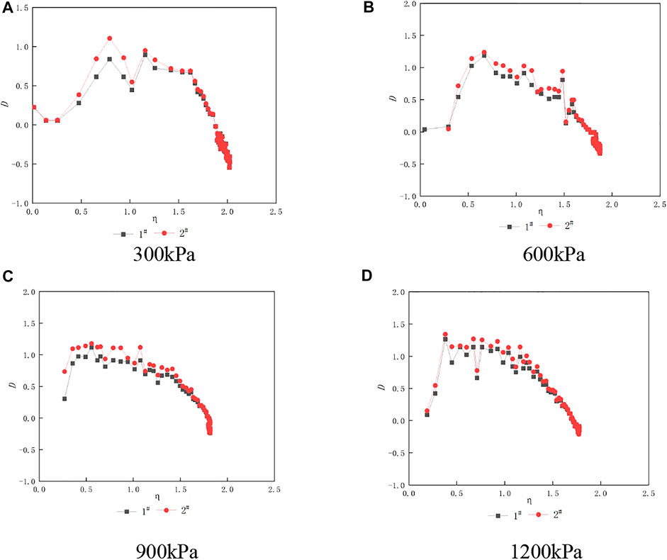
FIGURE 11. The dilatancy ratio of LCSG material with cemented content of 20kg/m3 under different confining pressures. (A) 300 kPa (B) 600 kPa (C) 900 kPa (D) 1,200 kPa.
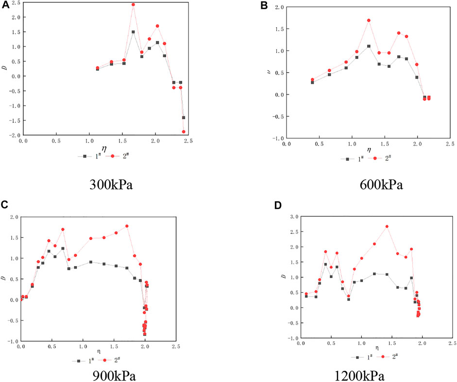
FIGURE 12. The dilatancy ratio of LCSG material with cemented content of 60kg/m3 under different confining pressures. (A) 300 kPa (B) 600 kPa (C) 900 kPa (D) 1,200 kPa.
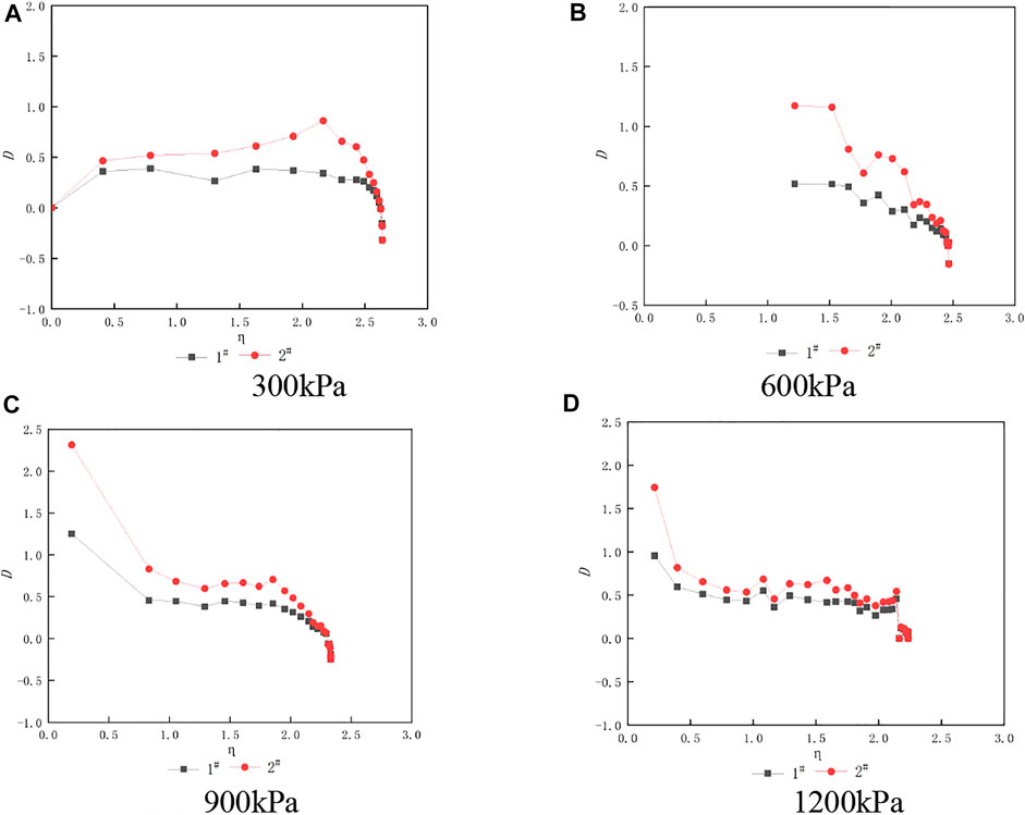
FIGURE 13. The dilatancy ratio of LCSG material with cemented content of 100kg/m3 under different confining pressures. (A) 300 kPa (B) 600 kPa (C) 900 kPa (D) 1,200 kPa.
As shown in the figure, for LCSG material with a cement content of 20 kg/m3, when the stress ratio η is under range 1.0–2.0, the dilatancy ratio formed by elastic strain is slightly smaller than that formed by plastic strain, and the difference in the dilatancy ratio from other stress ratios is small, indicating that the dilatancy characteristics of LCSG material with a low cement content are less affected by elastic strain. In engineering simulation, the ratio of total volume strain to axial strain increment can be directly adopted according to the common rockfill method. When the stress ratio is 1.0–2.0, the elastic dilatancy ratio is significantly smaller than the plastic dilatancy ratio, and the difference between the two ratios gradually increases with the confining pressure. The difference is very small under other stress ratios. When the cement content reaches 100 kg/m3, the dilatancy ratio of the total volume strain to axial strain before LCSG material failure is smaller than the incremental ratio of plastic volume strain and increases with the confining pressure. The above differences indicate that the difference between the two dilatancy ratios gradually increases with the cement content. When developing the dilatancy formula, the dilatancy properties evaluated according to the total dilatancy ratio may be smaller than the actual value, thus overestimating the hardness of the cemented materials. The above phenomenon is attributed to the fact that, when the gel content is low, the mechanical properties of gelling gravel stone are similar to those of rockfill and the effects of elastic deformation are negligible. With an increase in the cement content and the increase of the material by its cementation performance, its performance is closer to the concrete characteristics of its dilatancy properties directly, and using the plastic strain increment is more accurate.
Conclusion
In this study, by conducting laboratory triaxial compression, triaxial equiaxial loading and unloading, and triaxial loading and unloading tests on LCSG samples under different cement contents and confining pressures, their mechanical properties, including dilatancy characteristics, were examined. The following main conclusions are drawn:
1) Under the same confining pressure during triaxial unloading and reloading, hysteretic loops appear in the stress–strain curve of LCSG material. With an increase in stress level, the size of the loops increases, but the shape remains constant. Hysteretic loops also appear in LCSG material subjected to triaxial equidirectional loading and unloading. With an increase in consolidation stress, the size of the loops increases, but the shape remains unchanged.
2) To illustrate the influence of elastic deformation on the dilatancy equation, the elastic shear modulus and volume modulus are determined according to the triaxial axial unloading and reloading curves and the isotropic loading and unloading curves, respectively.
3) The dilatancy model of LCSG material with low cement content can be determined directly according to the volumetric strain–axial strain equation, without considering the influence of elastic deformation. With an increase in cement content, the dilatancy value determined by the total volume strain increment ratio becomes smaller than that determined by the plastic strain increment ratio, and the influence of elastic deformation cannot be ignored.
The above research results can provide an important theoretical basis for the structural numerical simulation of LCSG dams and other engineering structures.
Data Availability Statement
The experimental and calculated data used to support the findings of this study are available from the corresponding author upon reasonable request.
Author Contributions
HY, Organization and analysis X-mS, Provide materials Y-cY, Experiment JY, Writing C-hZ, Correspondent.
Funding
This research was funded by the National Natural Science Foundation of China, grant numbers 41871313 and 51808298; the Basic Public Welfare Research Project of Zhejiang, China, grant number LGF20E090002; the Natural Science Foundation of the Higher Education Institutions of Jiangsu Province, China, grant number 20KJB570001, and the Nantong University College Students' innovation and entrepreneurship training program (Grant No. 202110304115Y).
Conflict of Interest
The authors declare that the research was conducted in the absence of any commercial or financial relationships that could be construed as a potential conflict of interest.
Publisher’s Note
All claims expressed in this article are solely those of the authors and do not necessarily represent those of their affiliated organizations, or those of the publisher, the editors, and the reviewers. Any product that may be evaluated in this article, or claim that may be made by its manufacturer, is not guaranteed or endorsed by the publisher.
References
Amini, Y., and Hamidi, A. (2014). Triaxial Shear Behavior of a Cement-Treated Sand-Gravel Mixture. J. Rock Mech. Geotechn. Eng. 6 (5), 455–465. doi:10.1016/j.jrmge.2014.07.006
Cai, X., Yang, J., Guo, X. W., and Wu, Y. L. (2016). Elastoplastic Constitutive Model for Cement-Sand-Gravel Material. Chin. J. Geotechn. Eng. 38 (9), 1569–1577. doi:10.11779/CJGE201609003
Chu, Y. F., Zhu, J. G., and Jia, H. (2012). Experimental Study of Mechanical Behaviour of Coarse-Grained Soil in Unloading and Reloading. Rock Soil Mech. 33 (4), 1061–1066.
Feng, W. (2013). Studies on Cemented Sand and Gravel Dam Material and its Application. Beijing, China: China Institute of Water Resources & Hydropower Research.
Fu, H., Chen, S. S., Han, H. Q., Ling, H., and Cai, X. (2015). Experimental Study on Static and Dynamic Properties of Cemented Sand and Gravel. Chin. J. Geotechn. Eng. 37, 357–362. doi:10.1139/t2012-069
Jia, J. S., Liu, N., Zheng, C. Y., Ma, F. L., Du, Z. K., and Wang, Y. (2016). Research Progress and Engineering Application of Cemented Granular Dam. J. Water Conserv. 47 (3), 315–323. doi:10.1016/J.ENG.2016.04.003
Jiang, J. S., Cheng, Z. L., Zuo, Y. Z., and Ding, H. S. (2014). Dilatancy of Coarse-Grained Soil in Large-Scale Triaxial Tests Study. Rock Soil Mech. 35 (11), 3129–3138.
Jin, L., Zeng, Y. W., and Zhang, S. (2017). Large Scale Triaxial Tests on Effects of Rock Block Proportion and Shape on Mechanical Properties of Cemented Soil-Rock Mixture. Rock Soil Mech. 38 (1), 141–149. doi:10.16285/j.rsm.2017.01.018
Kong, Y. X., Shen, F. F., and Wang, H. J. (2018). Stress-dilatancy Properties for Fiber-Reinforced Sand. Chin. J. Geotechn. Eng. 40 (12), 2249–2256. doi:10.11779/CJGE201812012
Liu, M. C., Gao, Y. F., and Liu, H. L. (2008). Study on Shear Dilatancy Behaviors of Rockfills in Large-Scale Triaxial Tests. Chin. J. Geotechn. Eng. 30 (2), 205–211.
Liu, Y., Chen, J. H., and Zhu, Z. Q. (2019). Static Mechanical Properties of Argillaceous Slate Coarse-Grained Soil Improved by Cement. J. Cent. South Univ. 50 (1), 139–145. doi:10.11817/j.issn.1672-7207.2019.01.018
Londe, P., and Lino, M. (1992). The Faced Symmetrical Hardfill Dam: a New Concept for RCC. Int. Water Power Dam Constr. 44 (2), 19–24.
Rowe, P. W. (1962). “The Stress-Dilatancy Relation for Static Equilibrium of an Assembly of Particles in Contact,” in Proceedings of the Royal Society of London A: Mathematical, Physical and Engineering Sciences, London, October 9, 1962 (London: The Royal Society).
SL237-1999, Specification of Soil Test, (1999). SL237-1999, Specification of Soil Test. Beijing, China: Ministry of Water Resources of the People's Republic of China.
SL678-2014, Technical Guide Line for Cemented Granular Material Dams Particles, (2014). SL678-2014, Technical Guide Line for Cemented Granular Material Dams Particles. Beijing, China: Ministry of Water Resources of the People's Republic of China.
Sun, M. Q. (2016). Study on Mechanical Properties, Durability and Dam Shape of Cemented Sand and Gravel. Beijing, China: China Water Resources and Hydropower Press.
Wang, Y., Jia, J. S., and Ren, Q. (2018). Study on Performance of Rich-Mix Cemented Sand, Gravel and Rock Reinforced by Fiber. Water Resour. Hydropower Eng. 49 (11), 204–210. doi:10.1155/2018/2531642
Wang, Z. J., Chen, S. S., and Fu, Z. Z. (2015). Dilatancy Behaviors and Generalized Plasticity Constitutive Model of Rockfill Materials. Rock Soil Mech. 36 (7), 1931–1938. doi:10.16285/j.rsm.2015.07.013
Wei, K. M., Chen, S. S., and Li, G. Y. (2019). Elastoplastic Model for Cemented Coarse-Grained Materials and its Application. Chin. J. Geotechn. Eng. 41 (5), 797–805.
Wei, K. M., Chen, S. S., Li, G. Y., and Fu, Z. Z. (2016). Constitutive Model for Coarse-Grained Dam Materials Considering State Parameter. Chin. J. Geotechn. Eng. 38 (4), 654–661. doi:10.11779/CJGE201604009
Wu, M., Du, B., Yao, Y., and He, X. (2011). An Experimental Study on Stress-Strain Behavior and Constitutive Model of Hardfill Material. Sci. China Phys. Mech. Astron. 54 (11), 2015–2024. doi:10.1007/s11433-011-4518-3
Xu, W.-b., Liu, B., and Wu, W.-l. (2020). Strength and Deformation Behaviors of Cemented Tailings Backfill under Triaxial Compression. J. Cent. South. Univ. 27, 3531–3543. doi:10.1007/s11771-020-4568-7
Yang, G., Sun, X., and Wang, Y. Y. (2018). Tests on Resilient Behaviour of Polymer Rockfill Materials. Rock Soil Mech. 39 (5), 1669–1674. doi:10.16285/j.rsm.2016.1612
Yang, J., Cai, X., Guo, X. W., and Zhao, J. L. (2019). Effect of Cement Content on the Deformation Properties of Cemented Sand and Gravel Material. Appl. Sci. Basel 9, 1–16. doi:10.3390/app9112369
Yang, J., Cai, X., Pang, Q., Guo, X.-w., Wu, Y.-l., and Zhao, J.-l. (2018). Experimental Study on the Shear Strength of Cement-Sand-Gravel Material. Adv. Mater. Sci. Eng. 2018, 1–11. doi:10.1155/2018/2531642
Yao, Y. P., Luo, T., and Hou, W. (2018). Constitutive Relation of Soil. Beijing, China: China Communications Press Co., Ltd.
Yu, J., Jia, C., Xu, W., Zhang, Q., and Wu, C. J. (2021). Granular Discrete Element Simulation of the Evolution Characteristics of the Shear Band in Soil–Rock Mixture Based on Particle Rotation Analysis. Environ. Earth Sci. 80 (6), 213. doi:10.1007/s12665-021-09484-y
Keywords: LCSG materials, large-scale triaxial tests, dilatancy characteristics, triaxial compression tests, isodirectional loading and unloading tests
Citation: Yu H, Shen X-m, Ye Y-c, Yang J and Zhu C-h (2021) Large-Scale Triaxial Tests on Dilatancy Characteristics of Lean Cemented Sand and Gravel. Front. Earth Sci. 9:799215. doi: 10.3389/feart.2021.799215
Received: 21 October 2021; Accepted: 06 December 2021;
Published: 21 December 2021.
Edited by:
Chaojun Jia, Central South University, ChinaReviewed by:
Qiang Zhang, China Institute of Water Resources and Hydropower Research, ChinaShengnian Wang, Nanjing Tech University, China
Copyright © 2021 Yu, Shen, Ye, Yang and Zhu. This is an open-access article distributed under the terms of the Creative Commons Attribution License (CC BY). The use, distribution or reproduction in other forums is permitted, provided the original author(s) and the copyright owner(s) are credited and that the original publication in this journal is cited, in accordance with accepted academic practice. No use, distribution or reproduction is permitted which does not comply with these terms.
*Correspondence: Chen-hui Zhu, emNoMTk4OTE2QG50dS5lZHUuY24=