- 1Department of Civil Engineering,School of Civil Engineering, Hunan University of Science and Technology, Xiangtan, China
- 2Foshan Transportation Science and Technology Limited Company, Foshan, China
In order to study the three-dimensional stability problem of the saturated soft clay slope under earthquake loads, based on the three-dimensional rotation failure model, the seismic force was introduced into the calculation by the quasi-static method. The work rate of external loads and the internal energy dissipation rate of the saturated soft clay slope were calculated using the upper bound method of limit analysis, and the analytical solution of stability coefficient of saturated soft clay slopes was derived based on the fictitious power principle. By virtue of the exhaust algorithm, the optimal solution of stability coefficient of saturated soft clay slopes was obtained. The influence of the slope angle and the horizontal and vertical seismic forces on the stability coefficient of saturated soft clay slope was analyzed. The results show that the slope angle has a great influence on the stability coefficient, and the relative difference is up to 35.7%. Therefore, the stability coefficient of saturated soft clay slopes can be effectively increased by a proper slope setting. The horizontal and vertical seismic forces also have a significant influence on the stability of saturated soft clay slopes. The relative differences of the stability coefficient under horizontal and vertical seismic forces are as high as 41 and 14.7%, respectively. If they are ignored, the stability coefficient of saturated soft clay slopes will be seriously overestimated. It is suggested that the effects of horizontal and vertical seismic forces must be considered simultaneously in the seismic design of saturated soft clay slopes.
1 Introduction
Safety of the slope has always been a concern in engineering. Soil slopes are usually made of clay, sand, silt, etc. These soil slopes tend to fail under the action of earthquake and other external loads, thus causing huge loss to related projects (Leong and Rahardjo 2012; Gofar and Rahardjo 2017; VandenBerge and McGuire 2019).
Alejano et al. (2011), Selcuk et al. (2015) concluded that considering the safety of slope under the action of earthquake, the limit analysis method and the limit equilibrium method are mainly adopted. Michalowski and Park (2020) believe that the principle of limit equilibrium method is simple, but it only considers the yield condition and stress equilibrium condition of soil, and ignores the constitutive relation between soils. The limit analysis method overcomes this defect and establishes the constitutive relation of soil through the flow law (Yang and Liu 2018). Compared with the limit equilibrium method, it is stricter in theory and more accurate in calculation, so it becomes an efficacious method to ensure the slope safety (Gischig et al., 2015; Rawat and Gupta 2016). The stability of the slope is considered by using the limit analysis method, and at present, the two-dimensional plane strain problem is gradually developed into a three-dimensional problem. In view of the complex soil slope, Jongmin et al. (2002) analyzed the slope stability and found that the method of limit analysis is better than the limit equilibrium method. Yao and Yang (2017) studied the stability of the unsaturated soil slope by introducing a uniform shear strength formula to consider the influence of intermediate principal stress. For the three-dimensional stability of the slope, Huang et al. (2002) expanded the 3D stability analysis method, making it possible to use “ two-directional force and moment equilibrium” in any shape of 3D failure mechanism. This method can accurately compute the sliding direction of the failure surface and reduce the tedious work of conventional methods. Gao et al. (2015) extended the plane strain analysis of the slope strengthened by pile arrangement to the three-dimensional situation and used the limit analysis upper limit method to determine the safety coefficient. Aiming at the safety of the unsaturated three-dimensional soil slope under the condition of steady seepage, Wang et al. (2019) studied the safety of the 3D slope under the suction induction effect and permeability. Han et al. (2014) analyzed the effect of heterogeneity and anisotropy on the safety of 3D slopes.
So far, there have been many results of using the upper limit method to discuss the safety of slopes under earthquake problems. In 2009, Michalowski and Drescher (2009), Michalowski (2010) put forward a 3D rotational failure mechanism of the slope and investigated the impact of seismic forces on the slope stability and safety coefficient by the upper limit method. On the basis of the upper limit theorem of limit analysis, Nian et al. (2016) introduced the quasi-static method to research the safety of the anchored slope under the action of seismic forces. Zhang et al. (2016) studied the impact of seismic forces on the safety of the 3D slope by using the limit analysis upper bound method. Sahoo et al. (2016) studied the seismic failure mechanism of the non-reinforced soil slope and reinforced soil slope in detail using the shaking table test. To sum up, there are many research studies on the seismic problem of the slope, but few studies on the simultaneous action of horizontal and vertical seismic forces and saturated soft clay. Therefore, in this work, the effect of horizontal and vertical seismic forces on the stability of the saturated soft clay slope was studied based on the 3D rotational failure mechanism of the slope and the limit analysis upper bound method combined with the quasi-static method, so as to provide reference for the seismic design of similar projects in the future.
2 Upper Bound Theorem of Limit Analysis
The aim of the upper bound theorem of limit analysis is to solve the limit failure load; for any hypothetical failure mode satisfying the allowable velocity field of motion, the upper limit of the ultimate load is the load obtained from the external power equal to the dissipated power of internal energy. The formula can be expressed as follows (Chen 2007; Yang and Wang 2018):
where σij and ɛ̇ij are the stress state and the volume change rate at any point in the plastic failure zone, respectively; V and Fi are the volume and volume force of the unit in the plastic failure zone respectively; S and Ti are the surface area and surface force of the element in the plastic failure zone, respectively; and vi* refers to the velocity along the sliding surface.
3 3D Failure Mechanism
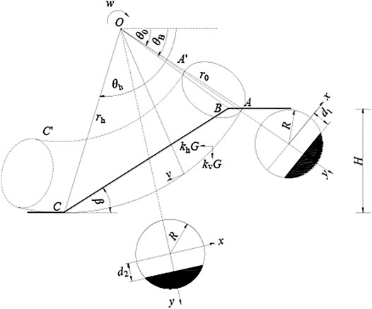
Figure 1 shows the 3D rotational failure mechanism for saturated soft clay slopes. Rotating the failure surface around O point with angular velocity ω, it passes through A point at the top of the slope and C point at the toe of the slope, forming two logarithmic spiral curves of AC and A´C´, where the angle between OA and OA´ and the horizontal direction is θA, the lengths are r0 and r0´, respectively, the radius of C is rh, the angle of OB is θB, the angle between the direction diameter and the horizontal direction of any point on arcs AC and A´C´ is θ, and the lengths are r and r´, respectively. As shown in Figure 1, the plane perpendicular to the paper surface at O point intersects with the 3D rotational failure mechanism to form a circle; a rectangular coordinate system is established on the circle, with the positive direction of the Y-axis along the radial direction. Here, R is the radius of the circle and rm is the radius of the center of the circle.
According to geometry,
where f1 and f2 are, respectively:
In order to reflect the state of saturated soft clay slope failure more truly, a block with width b is inserted into the middle of the 3D rotational failure mechanism, as shown in Figure 2; as b→+∞, the 3D failure mechanism degenerates to a 2D plane strain condition. The combined failure mechanism can be used to analyze the 3D stability of saturated soft clay slopes of any width; in the analysis of this study, let the maximum width of the 3D rotational failure mechanism with insert block be b2, and the maximum width of the failure mechanism without insert block be b1, then b + b1 = b2.
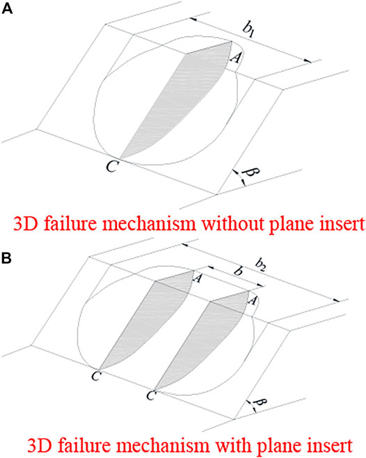
FIGURE 2. 3D failure mechanism. (A) 3D failure mechanism without plane insert, (B) 3D failure mechanism with plane insert.
4 Calculation of the Work Rates
In this study, the saturated soft clay slope with a single soil layer is calculated, and the following assumptions are made: 1) the soil mass satisfies the ideal elastic–plastic model and complies with the Mohr–Coulomb failure criterion and the associated flow law, and 2) for saturated soft clay, the calculation assumes that its internal friction angle value is close to 0.
4.1 The External Work Rates
In the calculation, the 3D rotational failure mechanism of the saturated soft clay slope is divided into two parts: the 3D rotational failure mechanism without the plane insert and with the plane insert, respectively; finally, the two are superimposed. The external work rates are composed of the work rates of soil weight and seismic forces.
1) The work rates of soil weight
The work rates of soil weight Wγ are divided into two parts for the calculation: the first part is the 3D rotational failure mechanism without plane insert Wγ-3D.
where γ is the soil weight, and g1 is the intermediate variable.
The other part is the work rate of soil weight with plane insert Wγ-insert.
where g2 is the intermediate variable.
In summary, the work rate of the total soil weight Wγ in the 3D rotational failure mechanism with a plane insert is as follows:
where
where f3 and f4 are dimensional functions of 1.
2) The work rates of seismic force
In this article, the pseudo-static method is used to analyze the stability of the three-dimensional slope. According to the pseudo-static method, the horizontal seismic force Fkh = khG and the vertical seismic force Fkv = kvG, where G is soil gravity and kh is the horizontal seismic coefficient. According to the Code for Seismic Design of Buildings GB50011-2010 (China), its value generally ranges from 0 to 0.3; kv is the vertical seismic coefficient, kv = ζkh, and ζ is the vertical earthquake proportional coefficient. Because the effect of vertical earthquake is less than that of horizontal earthquake, its value generally ranges from −1 to 1. When ζ > 0, the vertical earthquake force is downward.
The work rate by the horizontal seismic forces in the 3D rotational failure mechanism without the plane insert
where g3 is the intermediate variable.
Similarly, the work rate generated by the horizontal seismic forces acting on plane insert
where g4 is the intermediate variable.
In summary, the work rates generated by the total horizontal seismic forces in the 3D rotational failure mechanism without the plane insert
Similar to the work done by the horizontal seismic forces, the work rates of vertical seismic forces are also composed of two parts: the 3D rotational failure mechanism without plane insert
the work rate generated by the horizontal seismic forces acting on plane insert
Therefore, the total work rates of vertical seismic forces, which act on the 3D rotational failure mechanism without plane insert
In summary, the work rates of soil weight and seismic forces in the 3D rotational failure mechanism with plane insert, namely, the external work rates can be expressed as follows:
4.2 Internal Energy Dissipation
The internal energy dissipation rates of the 3D rotational failure mechanism without the plane insert are calculated, and the saturated soft clay slope is divided into AB and BC parts along the extension line of OB, the internal energy dissipation rates are DAB-3D and D BC-3D, respectively:
where c is the cohesion of soil, and g5 and g6 are intermediate variables, respectively.
The internal energy dissipated rates acting on the plane insert D insert are as follows:
where v is the velocity and g7 is the intermediate variable.
In summary, the total internal energy dissipated rates can be expressed as follows:
where
where ρ is the direction diameter of any point and ω is the angular velocity at this point.
4.3 Upper Bound Solution
As the internal energy dissipation rate and external work rate are equal, the critical height of the saturated soft clay slope can be obtained as follows:
In order to analyze the stability of the 3D saturated soft clay slope, the stability factor NL is introduced in this article. Under the Mohr–Coulomb failure criterion, the stability factor of the saturated soft clay slope can be defined as follows:
The stability of the slope is different with the sliding surface. Therefore, we need to take different θ0 and θh to calculate different NL according to Eqs. 32, 33. The minimum NL is the stability factor of the slope, and the corresponding θ0 and θh determine the slip surface of the slope. The formula to solve the stability factor NL is complicated, and it needs to be calculated by MATLAB software.
In addition, in the calculation, f3∼ f10 and g1 ∼ g7 are functions of dimension 1, and their expressions are, respectively, given as follows:
5 Comparison
In order to simplify the study, the research object of this article is the same as Michalowski and Drescher (2009), and the friction problem of complex clays is not considered. Without considering the seismic load (kh = 0, kv = 0), the stability factor NL of the saturated soft clay slope (φ = 0) is calculated. Table 1 shows the comparisons between the stability factors calculated in the work and the results of Michalowski and Drescher (2009). As can be seen from Table 1, the results of the two methods are quite similar, and the maximum error is only 10.2%. It shows that calculation in this article is effective.
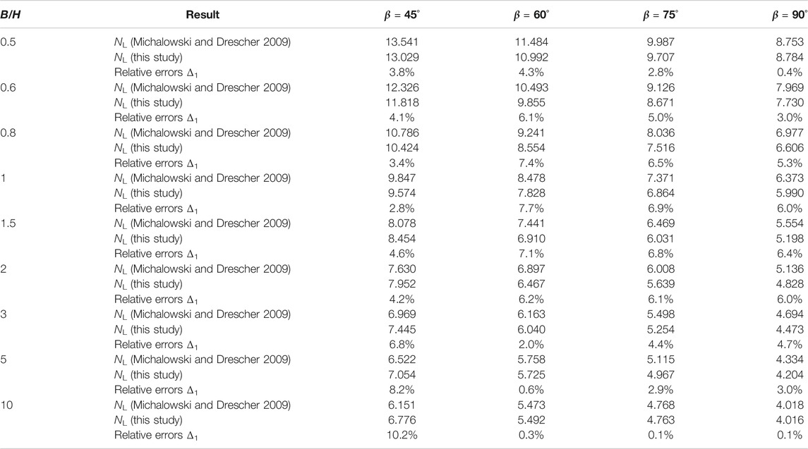
TABLE 1. Comparing the results between this study and Michalowski and Drescher (2009).
6 Results Analysis
6.1 Influence of Slope Width-to-Height Ratio and Slope Angle
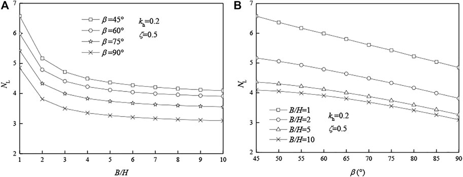
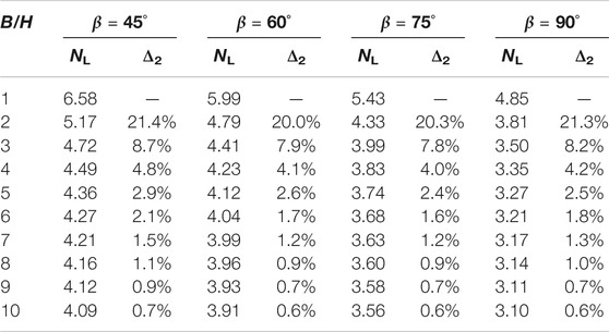
Considering the seismic load (kh = 0.2, ζ = 0.5), the influence of B/H and β on stability factors is shown in Figure 3. As shown in Figure 3A, the slope stability factor NL decreases with the increase in B/H, and the decreasing trend becomes more gentle and finally tends to level. As can be seen from Table 2, when B/H ≥ 8 and β = 45°, 60°, 75°, and 90°, the relative error between stability factors is only 1%. Assume that the relative error allowed is 1%, and the conclusions are as follows:
1) When B/H = 1 or 2, the three-dimensional effect of the slope is very prominent, and the relative error between stability factors can reach 21.4%.
2) As B/H increases from 1 to 7, the stability coefficient of the slope decreases gradually, and the three-dimensional effect of the slope becomes less and less prominent.
3) When B/H ≥ 8, the stability factor of the slope is approximate to a certain value, and the three-dimensional slope can be simplified as a two-dimensional problem.
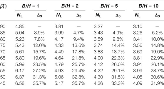
As shown in Figure 3B, when β increases, the slope stability factor NL decreases, and when B/H is larger (B/H = 10), NL decreases more. Compared with the original slope, when the slope angle increases, the sliding surface does not change, but the soil mass of the slope increases. The internal energy dissipation rate remains unchanged, and the external work rate increases, so the slope stability factor NL decreases. The larger the B/H is (such as B/H = 10), the more soil mass increases, and the greater the slope stability factor decreases.
As can be seen from Table 3, when the slope angle β decreases by 5° each time from 90° to 45°, the stability factor NL approximately increases by 1/3. The slope angle has a significant effect on slope stability, and reasonable design of a smaller slope angle is particularly important, which greatly increases the safety of the slope and reduces the possibility of slope landslide.
In conclusion, B/H and β significantly affect the stability factor NL. The ratio B/H represents the three-dimensional effect degree of the slope. When B/H is large enough (B/H ≥ 8), the slope stability can be simplified into a two-dimensional problem.
6.2 Influence of Horizontal Seismic Force
It can be seen from Figure 4, the stability factor NL of the saturated soft clay slope decreases with the increase in kh. As the critical height Hc decreases, both the rate of external work and the rate of internal energy dissipation decrease, but the work rate of external force decreases more. When the horizontal seismic force increases, the work rate of the three-dimensional slope increases. According to the conservation of energy, the critical height Hc of the slope decreases, so the stability factor NL decreases.
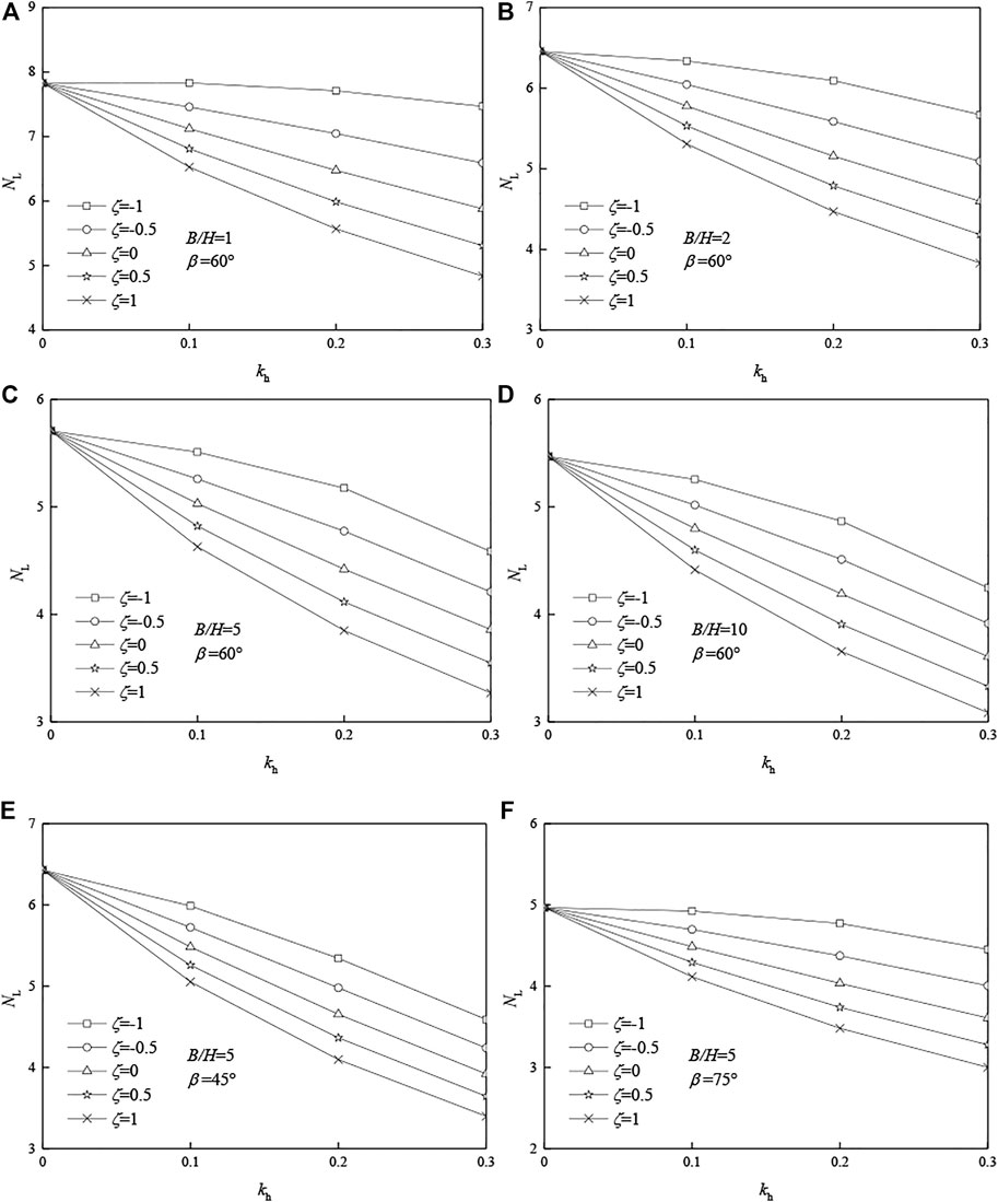
FIGURE 4. Effects of the horizontal seismic effect coefficient kh on stability factor NL: (A) B/H = 1, β = 60°; (B) B/H = 2, β = 60°; (C) B/H = 5, β = 60°; (D) B/H = 10, β = 60°; (E) B/H = 5, β = 45°; (F) B/H = 5, β = 75°.
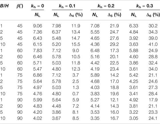
As can be seen from Table 4, taking B/H = 1, β = 45° as an example, without considering the effect of horizontal seismic force (kh = 0), the safety factor is 9.06. When kh increased from 0.1 to 0.3, the safety factor NL decreased from 7.98 to 6.33. Compared with kh = 0, the minimum relative error was 11.9% and the maximum was 30.2%.
Taking B/H = 10, β = 45° as an example, without considering the effect of horizontal seismic force (kh = 0), the safety factor is 6.15. When kh increased from 0.1 to 0.3, the safety factor NL decreased from 5.20 to 3.63. Compared with kh = 0, the minimum relative error was 15.5% and the maximum was 41.0%.
It shows that the horizontal seismic force obviously affects the safety factors of saturated soft clay slope. Especially when B/H is large, the slope stability problem can be regarded as a two-dimensional problem. If the influence of the horizontal seismic force is ignored, the stability factor of the slope will be significantly overestimated.
6.3 Influence of Vertical Seismic Force
It can be seen from Figure 5, when the vertical seismic effect proportion coefficient ζ increases, the stability factor NL of the saturated soft clay slope decreases. When ζ > 0, the vertical seismic force is downward, which is not conducive to the stability of the slope. When the vertical seismic force increases, the work rate of the three-dimensional slope increases. According to the conservation of energy, the critical height Hc of the slope decreases, so the stability factor NL decreases.
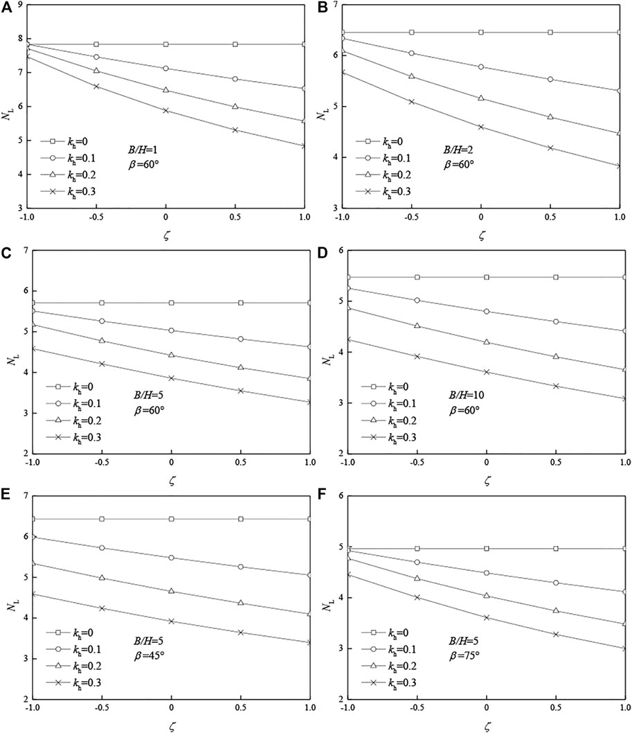
FIGURE 5. Effects of the vertical seismic effect proportion coefficient ζ on stability factor NL. (A) B/H = 1, β = 60°; (B) B/H = 2, β = 60°; (C) B/H = 5, β = 60°; (D) B/H = 10, β = 60°; (E) B/H = 5, β = 45°; (F) B/H = 5, β = 75°.
As can be seen from Table 5, taking B/H = 1, β = 45° as an example, without considering the effect of vertical seismic force (ζ = 0), the safety factor is 7.08. When ζ increased from 0.5 to 1, the safety factor NL decreased from 6.58 to 6.14. Compared with ζ = 0, the minimum relative error was 7.1% and the maximum was 13.2%.
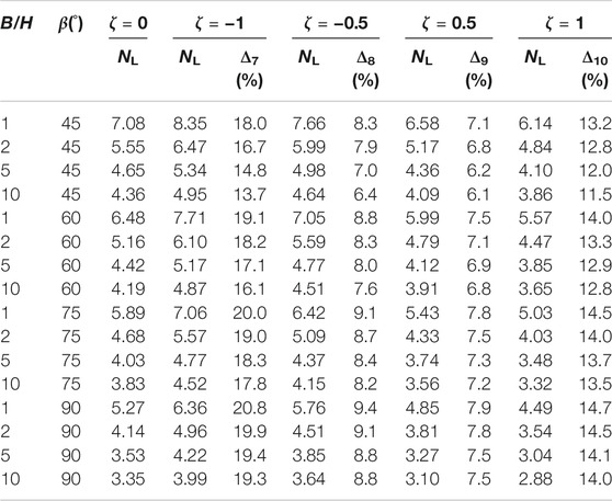
TABLE 5. Effects of the vertical seismic effect proportion coefficient ζ on stability factor NL (kh = 0.2).
Taking B/H = 10, β = 45° as an example, without considering the effect of vertical seismic force (ζ = 0), the safety factor is 4.36. When ζ increased from 0.5 to 1, the safety factor NL decreased from 4.09 to 3.86. Compared with ζ = 0, the minimum relative error was 6.1% and the maximum was 11.5%.
It shows that the vertical seismic force also has great influence on the stability of the saturated soft clay slope. If the vertical seismic force effect is ignored, the accuracy of calculation results will be directly affected.
Horizontal and vertical seismic loads have significant effects on slope stability. Therefore, in practical engineering, the influence of earthquake on slope stability needs to be considered, and the slope structure must be designed according to relevant seismic design code in order to ensure the stability of the slope.
7 Conclusion
1) The safety factors calculated in this article are very close to the results of Michalowski and Drescher (2009). The maximum error is only 7.7%, which shows that the calculation method in this article is effective.
2) The ratio B/H represents the three-dimensional effect degree of the saturated soft clay slope. Considering the effect of seismic load (kh = 0.2, ζ = 0.5), the conclusions are as follows:
(a) When B/H = 1 or 2, the three-dimensional effect of the slope is very obvious.
(b) When B/H increases from 1 to 7, the three-dimensional effect of the slope gradually weakens.
(c) When the B/H ≥ 8, the three-dimensional slope stability problem can be simplified to a two-dimensional problem.
3) The stability factor NL increases with the decrease in slope angle β. When the slope angle decreases from 90° to 45°, the stability coefficient NL increases approximately 1/3. It is suggested that slope angle should be considered in the design of saturated soft clay slope.
Data Availability Statement
The original contributions presented in the study are included in the article/Supplementary Material; further inquiries can be directed to the corresponding author.
Author Contributions
The overarching research goals were developed by BZ. BZ established the models and analyzed the formal. YJ analyzed the results and wrote the initial draft of the manuscript. BZ and ZL revised and polished the manuscript. HC offered proposals and polished the manuscript. All authors listed have made a substantial, direct, and intellectual contribution to the work and approved it for publication.
Funding
This study was funded by the National Natural Science Foundation of China (52004088 and 52074116) and the Science Foundation of Hunan University of Science and Technology (E52076).
Conflict of Interest
Author HC is employed by Foshan Transportation Science and Technology Limited Company.
The remaining authors declare that the research was conducted in the absence of any commercial or financial relationships that could be construed as a potential conflict of interest.
Publisher’s Note
All claims expressed in this article are solely those of the authors and do not necessarily represent those of their affiliated organizations, or those of the publisher, the editors, and the reviewers. Any product that may be evaluated in this article, or claim that may be made by its manufacturer, is not guaranteed or endorsed by the publisher.
References
Alejano, L. R., Ferrero, A. M., Ramírez-Oyanguren, P., and Álvarez Fernández, M. I. (2011). Comparison of Limit-Equilibrium, Numerical and Physical Models of wall Slope Stability. Int. J. Rock Mech. Mining Sci. 48, 16–26. doi:10.1016/j.ijrmms.2010.06.013
Alemdag, S., KayaMustafa, A. K., Karadag, M., Gurocak, Z., and Bulut, F. (2015). Utilization of the Limit Equilibrium and Finite Element Methods for the Stability Analysis of the Slope Debris: An Example of the Kalebasi District (NE Turkey). J. Afr. Earth Sci. 106, 134–146. doi:10.1016/j.jafrearsci.2015.03.010
Ausilio, E., Conte, E., and Dente, G. (2000). Seismic Stability Analysis of Reinforced Slopes. Soil Dyn. Earthquake Eng. 19, 159–172. doi:10.1016/S0267-7261(00)00005-1
Gao, Y.-f., Ye, M., and Zhang, F. (2015). Three-dimensional Analysis of Slopes Reinforced with Piles. J. Cent. South. Univ. 22, 2322–2327. doi:10.1007/s11771-015-2757-6
Gischig, V. S., Eberhardt, E., Moore, J. R., and Hungr, O. (2015). On the Seismic Response of Deep-Seated Rock Slope Instabilities - Insights from Numerical Modeling. Eng. Geology. 193, 1–18. doi:10.1016/j.enggeo.2015.04.003
Gofar, N., and Rahardjo, H. (2017). Saturated and Unsaturated Stability Analysis of Slope Subjected to Rainfall Infiltration. MATEC Web Conf. 101, 05004. doi:10.1051/matecconf/201710105004
Han, C.-y., Chen, J.-j., Xia, X.-h., and Wang, J.-h. (2014). Three-dimensional Stability Analysis of Anisotropic and Non-homogeneous Slopes Using Limit Analysis. J. Cent. South. Univ. 21, 1142–1147. doi:10.1007/s11771-014-2047-8
Huang, C.-C., Tsai, C.-C., and Chen, Y.-H. (2002). Generalized Method for Three-Dimensional Slope Stability Analysis. J. Geotech. Geoenviron. Eng. 128128, 83610–83848. doi:10.1061/(ASCE)1090-024110.1061/(asce)1090-0241(2002)128:10(836)
Jongmin, K., Rodrigo, S., and Lee, J. (2002). Stability Analysis of Complex Soil Slopes Using Limit Analysis. J. Geotechnical Geoenvironmental Eng. 128128, 5467–5557. doi:10.1061/(ASCE)1090-0241
Leong, E. C., and Rahardjo, H. (2012). Two and Three-Dimensional Slope Stability Reanalyses of Bukit Batok Slope. Comput. Geotechnics 42, 81–88. doi:10.1016/j.compgeo.2012.01.001
Li, A. J., Lyamin, A. V., and Merifield, R. S. (2009). Seismic Rock Slope Stability Charts Based on Limit Analysis Methods. Comput. Geotechnics 36, 135–148. doi:10.1016/j.compgeo.2008.01.004
Michalowski, R. L., and Drescher, A. (2009). Three-dimensional Stability of Slopes and Excavations. Géotechnique 59 (10), 839–850. doi:10.1680/geot.8.p.136
Michalowski, R. L., and Martel, T. (2011). Stability Charts for 3D Failures of Steep Slopes Subjected to Seismic Excitation. J. Geotech. Geoenviron. Eng. 137, 183–189. doi:10.1061/(asce)gt.1943-5606.0000412
Michalowski, R. L., and Park, D. (2020). Stability Assessment of Slopes in Rock Governed by the Hoek-Brown Strength Criterion. Int. J. Rock Mech. Mining Sci. 127, 1–12. doi:10.1016/j.ijrmms.2020.104217
National Standard of the People’s Republic of China (2010). Code for Seismic Design of Building (GB50011-2010). Beijing, China: China Architecture and Building Press.
Nian, T.-K., Jiang, J.-C., Wang, F.-W., Yang, Q., and Luan, M.-T. (2016). Seismic Stability Analysis of Slope Reinforced with a Row of Piles. Soil Dyn. Earthquake Eng. 84, 83–93. doi:10.1016/j.soildyn.2016.01.023
Rawat, S., and Gupta, A. K. (2016). Analysis of a Nailed Soil Slope Using Limit Equilibrium and Finite Element Methods. Int. J. Geosynth. Ground Eng. 2, 34. doi:10.1007/s40891-016-0076-0
Selcuk, A., Ayberk, K., and Mustafa, K (2015). Utilization of the limit equilibrium and finite element methods for the stability analysis of the slope debris: An example of the Kalebasi District (NE Turkey). Afr. Earth Sci.. doi:10.1016/j.jafrearsci.2015.03.010
Sahoo, S., Manna, B., and Sharma, K. G. (2016). Seismic Stability Analysis of Un-reinforced and Reinforced Soil Slopes. Geo-china. Int. Conf.. doi:10.1061/9780784480007.009
VandenBerge, D. R., and McGuire, M. P. (2019). Practical Use of Modified Hoek-Brown Criterion for Soil Slope Stability Analysis. Geotech Geol. Eng. 37 (6), 5441–5455. doi:10.1007/s10706-019-00991-1
Wang, L., Hu, W., Sun, D. A., and Li, L. (2019). 3D Stability of Unsaturated Soil Slopes with Tension Cracks under Steady Infiltrations. Int. J. Numer. Anal. Methods Geomech 43 (6), 1184–1206. doi:10.1002/nag.2889
Yang, X. L., and Liu, Z. A. (2018). Reliability Analysis of Three-Dimensional Rock Slope. Geomechanics Eng. 15 (6), 1183–1191. doi:10.12989/gae.2018.15.6.1183
Yang, X. L., and Wang, H. Y. (2018). Catastrophe Analysis of Active-Passive Mechanisms for Shallow Tunnels with Settlement. Geomechanics Eng. 15 (1), 621–630. doi:10.12989/gae.2018.15.1.621
Yao, C., and Yang, X. (2017). Limit Analysis of Unsaturated Soil Slope Stability Considering Intermediate Principal Stress and Strength Nonlinearity. Geotech Geol. Eng. 35, 2053–2063. doi:10.1007/s10706-017-0226-8
Keywords: saturated soft clay, slope stability, three-dimensional, failure model, upper bound theorem of limit analysis, quasi-static method
Citation: Zhang B, Jiang Y, Cheng H and Liu Z (2021) Upper Bound Analysis of the Stability of 3D Slopes in the Saturated Soft Clay Subjected to Seismic Effect. Front. Earth Sci. 9:795854. doi: 10.3389/feart.2021.795854
Received: 15 October 2021; Accepted: 24 November 2021;
Published: 22 December 2021.
Edited by:
Fei Meng, Swinburne University of Technology, AustraliaReviewed by:
Yongxin Li, Hefei University of Technology, ChinaR. M. Yuan, China Earthquake Administration, China
Sheng Zhang, University of Warwick, United Kingdom
Fu Huang, Changsha University of Science and Technology, China
Copyright © 2021 Zhang, Jiang, Cheng and Liu. This is an open-access article distributed under the terms of the Creative Commons Attribution License (CC BY). The use, distribution or reproduction in other forums is permitted, provided the original author(s) and the copyright owner(s) are credited and that the original publication in this journal is cited, in accordance with accepted academic practice. No use, distribution or reproduction is permitted which does not comply with these terms.
*Correspondence: Biao Zhang, MTAyMDE3NkBobnVzdC5lZHUuY24=
 Biao Zhang
 Yi Jiang1
 Hao Cheng