 Huan Zhao
 Wei Li1*
 Jian Jun Zhu
94% of researchers rate our articles as excellent or good
Learn more about the work of our research integrity team to safeguard the quality of each article we publish.
Find out more
ORIGINAL RESEARCH article
Front. Earth Sci., 31 January 2022
Sec. Economic Geology
Volume 9 - 2021 | https://doi.org/10.3389/feart.2021.784931
This article is part of the Research TopicNew Advances in Geology and Engineering Technology of Unconventional Oil and GasView all 24 articles
Natural fractures are common in unconventional reservoirs (e.g., tight oil and gas, shale oil and gas), for which hydraulic fracturing is the main exploitation method. Natural fractures influence the propagation and final transformation effect of hydraulic fractures, which is an important factor for fracture optimization design. In this work, the method of globally embedding zero-thickness cohesive zone elements is applied to establish a dynamic propagation model of hydraulic fractures in naturally fractured reservoirs, and the influence of natural fracture development on the fracture propagation patterns is investigated. The results show that the hydraulic fracture propagation paths in fractured reservoirs are highly complex, and steering, branching, and merging of the propagation paths may occur. When the natural fracture development is small, the fracture propagation pattern is mainly influenced by the minimum horizontal principal stress. In contrast, when the natural fracture development is large, the fracture propagation pattern is influenced by the natural fracture distribution. With increasing natural fracture angle, hydraulic fractures can easily pass through natural fractures and form wide fracturs. Higher numbers of natural fracture groups and fractal dimensions increase the number of fracture propagation directions and communicating natural fractures, and the fractures tend to be narrow and complex.
A large portion of global oil and gas resources occur in naturally fractured formations with low permeability. Hydraulic fracturing technology can improve the reservoir seepage characteristics, connect natural reservoir fractures, and improve the recovery of oil and gas, which are important for achieving economic benefits from fractured reservoirs (Tang et al., 2020; Xia et al., 2020; Jun et al., 2021; Ziyuan et al., 2022). However, the existence of natural fractures poses serious challenges in hydraulic fracturing design. Mayerhofer et al. first introduced the concept of a modified reservoir volume (Rahman and Rahman, 2010), and complex network structures have since become a common assumption in the predictions of the true state of hydraulic fractures in naturally fractured unconventional reservoirs. A quantification of the hydraulic fracture type at the field scale is difficult, but can be achieved by indirect measurements and observations and inter-well interference analysis, which can be used to infer the upper limits of the fracture size (Yuwei et al., 2017; et al., 2019; Nan et al., 2020). The field conditions of naturally fractured reservoirs typically include extremely high peritectic stresses, which cannot be appropriately replicated in laboratory-scale experiments. Numerical simulations thus provide a useful method to measure the propagation behavior of hydraulic fractures in naturally fractured reservoirs.
Natural fractures place important constraints on mining operations. A comprehensive understanding of the propagation law of hydraulic fractures in the presence of natural fractures is therefore critical and has attracted extensive research attention in recent years. Zhang et al. (Zhang and Jeffrey, 2006; Zhang et al., 2007) established a hydraulic fracture propagation model with fully coupled fluid flow and stresses caused by fracture tension/slip and friction evolution based on the displacement discontinuity method, and numerically simulated the interactions between hydraulic and pre-existing fractures. Dahi-Taleghani et al. (Dahi-Taleghani and Olson, 2011) simulated the propagation process of multiple hydraulic fractures and considered the interaction between hydraulic and natural fractures. Chuprakov et al. (Chuprakov et al., 2011) used the displacement discontinuity method and Mohr–Coulomb criterion to explain natural fractures and the mechanical activation mechanism responsible for the interaction between pressurized hydraulic fractures. Kresse et al. (Kresse et al., 2013) developed a complex fracture network model based on a two-dimensional boundary element model using an unconventional fracture model, and proposed a method to calculate stress shadows during the propagation of multiple fractures. Hou et al. (Bing et al., 2015) used the displacement discontinuity method to establish a two-dimensional model of multi-fracture propagation in a destination reservoir based on the theory of linear elastic fracture mechanics, and analyzed the complex morphology of hydraulic fracture propagation in a formation considering the interference of randomly distributed natural fractures. Cottrell et al. (Cottrell et al., 2013) established a discrete fracture network numerical model to simulate hydraulic fracture propagation in a natural fracture network and the interaction between hydraulic and natural fractures, and compared the results with those obtained from finite element numerical simulations. Xia et al. (Lei et al., 2016) performed discrete-element numerical simulations to establish a two-dimensional model of single-crack propagation, and analyzed the stress shadow effect on the fracture propagation direction. Fatahi (Fatahi et al., 2017) simulated the interaction between hydraulic and natural fractures based on a discrete-element numerical model, and verified the simulation results with experimental data. Chen (Zhiqiang et al., 2018) developed a hydrodynamic coupled LBM-DEM (Boltzmann method- discrete element method) model to study hydraulic fracture propagation in rocks with natural colluvial fractures. Bruno (Bruno and Einstein, 2014) applied ABAQUS software based on the extended finite element method to numerically simulate the stress field near the fracture tip, and analyzed the variation of the maximum principal stress and maximum shear stress at the hydraulic fracture tip in the presence of natural fractures and their effect on fracture initiation and propagation. Dehghan et al. (Dehghan et al., 2016) established various three-dimensional numerical models based on hydraulic fracture experiments using ABAQUS software, simulated the propagation of hydraulic fractures at the intersection with natural fractures using the extended finite element method, and found that the energy release rate significantly affects the propagation behavior of hydraulic fractures. Liu (Fei et al., 2017) proposed a novel fully coupled hydraulic fracture model using the extended finite element method to reveal the interaction mechanism between hydraulic fractures with orthogonal and nonorthogonal anisotropic angles and natural nonintersecting fractures.
The above models analyzed the behavior of hydraulic fracture propagation in the presence of natural fractures to some extent, but certain limitations remain. In this study, the cohesion model is used, which simulates complex fracture propagation and interaction mechanisms (Haddad et al., 2016). This model was first proposed by Dugdale (Dugdale, 1960) and Barenblatt (Barrenblatt, 1962) and is more capable of representing the discontinuities of brittle materials (e.g., rocks) than traditional finite element models. This method uses cohesive elements to simulate fracture formation, which avoids the problem of fracture tip singularity, and is now extensively used to simulate cracking in brittle materials (e.g., crystals, rocks). Yang et al. (Yang et al., 2009) developed an algorithm to freely embed cohesive elements in solid finite element meshes, which provides a reference and basis for simulating the fracturing of complex structures. Mokryakov (Mokryakov, 2011) established a cohesive force model for hydraulic fracturing that considers a reservoir’s plastic zone based on the fracture tip treatment presented in Barenblatt, developed a hydraulic fracture propagation model to improve the fitting accuracy of pressure logging, and applied the model to the problem of the intersection and propagation of hydraulic and natural fractures. Guo (Jianchun et al., 2015) established a coupled stress-percolation-damage model based on the cohesion method without introducing a fracture criterion, simulated the interaction between hydraulic and natural fractures, studied the intersection and propagation of hydraulic and natural fractures, and discussed the effects of stress field and pinch angle on fracture propagation. Wang (Wang, 2015; Wang, 2016) developed a hydraulic fracture model by considering pore elastic and pore plastic formations using the cohesion method, and analyzed the effect of plastic deformation near the fracture tip and inside the reservoir. Gonzalez and Dahi (Gonzalez and Dahi, 2015) investigated the intersecting hydraulic and natural fracture propagation process by modifying the intermediate nodes of the cohesion units embedded at the intersection of hydraulic and natural fractures. Chen (Chen et al., 2017) simulated the interaction between hydraulic and natural fractures using a cohesive finite element model. Dahi (Dahi et al., 2018) extended the cohesion model by introducing a fracture network, but the fracture propagation paths in the region needed to be predefined and the fractures could only propagate along predefined paths and weak planes. Wang (Wang, 2019) used the natural fracture distribution density, length, dip angle, and degree of cementation to develop a hydraulic fracture propagation model in a randomly fractured reservoir, and analyzed the effects of fracture size on proppant distribution and stress shading on fracture propagation.
Nevertheless, only a limited number of studies have addressed the behavior of hydraulic fractures in reservoirs containing fracture networks. Furthermore, most previous studies included pre-existing fracture propagation paths, which make it difficult to portray a fracture system with a large amount of fracture sets differently oriented in a reservoir. To address these issues, this study 1) combines the natural fracture network and global embedded cohesive element methods to establish a dynamic model of hydraulic fracture propagation in a fractured reservoir in accordance with the formation’s fractal characteristics; 2) analyzes the influence of different natural fracture system distributions on hydraulic fracture propagation; 3) eliminates the need for pre-existing fracture paths; and 4) more realistically reflects the hydraulic fracture propagation law of fractured formations.
To simulate the propagation of hydraulic and natural fractures, the proposed model involves the coupling of several physical processes, including 1) fracture propagation, 2) fluid flow within the fracture, 3) rock deformation near the fracture, and 4) fluid leakage in the porous medium. The theory of seepage is coupled with rock elastic deformation to describe the mechanical response of porous materials using the theory of pore elasticity.
The equilibrium equation of solid deformation can be described as follows (Diguang et al., 2016),
where b is the body force, N/m3. σ is the stress tensor, MPa. ε is the strain stress, m. u is the deformation displacement, m. D is Stiffness matrix in constitutive equation.
The basic theory of pore elasticity shows an explicit coupling between the propagation of a matrix skeleton and pressure of the diffusing pore fluid (Jianchun et al., 2015). The total stress (σij) can be expressed as:
where σ′ij is the effective stress, p is the pore pressure, α is the Biot constant, and δij is the Kronecker delta.
The rock tends to experience brittle damage and a cohesive unit is used to simulate the characteristics of the random fractures of rocky media. In this approach, a bilinear intrinsic model (Figure 1) is used to describe the relationship between traction force and displacement (Chen et al., 2009), i.e., linear elastic strengthening before damage and linear softening after damage. The area under the traction-displacement curve equals the critical fracture energy Gc (Wang, 2019).
where KIC is the stress intensity factor, E is the Young’s modulus, υ is Poisson’s ratio.
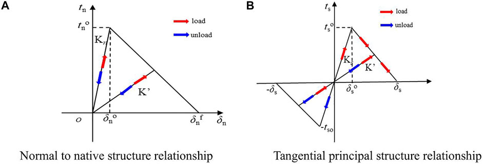
FIGURE 1. Bilinear constitutive model (A) Normal to native structure relationship (B) Tangential principal structure relationship.
The quadratic nominal stress criterion was selected as the initial damage criterion, which states that damage starts when the ratio of the square of the nominal stress in each direction is equal to 1, which can be expressed as:
where tn0 and ts0 are the peak nominal stresses when the normal and tangential deformations are perpendicular to the interface, respectively, tn and ts are the normal and tangential stress components, respectively, and the brackets indicate that damage is not caused by purely compressive deformation or the stress conditions.
In the bilinear constitutive relation, the cohesive unit follows the elastic constitutive relationship (Haddad and Sepehrnoori, 2015):
where K denotes the stiffness matrix of the cohesive unit in the elastic phase. During loading, the material stiffness K' is determined by the initial stiffness K and damage variable D. The damage response can be defined as:
where D is the damage variable scalar, which increases monotonically. When D = 0, the material is not damaged; when D = 1, the material is completely damaged.
`We assume that the fracturing fluid is an incompressible Newtonian fluid and the fluid flow in the cohesive units is divided into tangential and normal flow. Normal flow indicates the leakage of fracturing fluid into the formation and tangential flow is the driving force for fracture propagation (Guo et al., 2017), as shown in Figure 2.
where is qf is the average velocity per unit height, m2/s. w is fracture width, m. ql is the fluid loss, m/s.
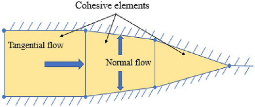
FIGURE 2. Fracturing fluid flow pattern within the cohesive element. The fluid flow continuity equation in the fracture is (Zhilong et al., 2008).
Normal flow in fractures is based on the following principles:
where qt and qb denote the fluid flow rate into the upper and lower surfaces of a cohesion element, respectively, ct and cb indicate the filter loss coefficients of the upper and lower surfaces, respectively, pi denotes the pressure in a cohesion element by virtual node interpolation, and pi and pb indicate the fluid pressure on the upper and lower surfaces of a cohesion element, respectively.
The strengths of natural fractures and rock media in a formation can substantially vary. During propagation, hydraulic fractures encounter natural fractures at a variety of interaction types (e.g., intersection, capture, blockage), and fracture propagation in rocks is difficult to predict. It is not possible to predetermine the location of embedded units within the model, and conventional models are required to prefabricate potential propagation paths. To gain insight into the influence of natural fractures on hydraulic fracture propagation and portray the propagation of simulated hydraulic fractures that intersect with natural fractures, the method of globally embedding zero-thickness cohesive units is implemented through secondary development. This approach assigns natural fractures and unit material rock properties, and simulates natural fractures and particle cementation in rocks. The fracture propagation process can thus be based on the judging criterion being free to expand in any unit.
The modeling method of zero-thickness viscous cohesion elements splits the nodes of the initial finite element mesh. Figure 3 shows a schematic diagram of the finite element mesh before and after embedding the viscous cohesion elements, and the zero-thickness viscous cohesion elements are embedded on the boundary of each solid element.
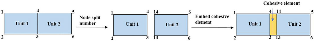
FIGURE 3. Quadrilateral grid zero-thickness cohesive element embedding.
The fracture direction is determined by the order of the nodes. The connecting units are numbered using the counterclockwise node numbering principle, and the first two node units are along the edges of the cohesive units. To avoid node number duplication, nodes at the same location are split, all units in the study area are traversed once, and the occurrence number of each node in the fractured area is recorded, the latter of which represents the number of times the node must be split. The node number is one number higher than the largest bit of the original maximum node number. The first value indicates the number of splits, followed by the original node number before the split, which forms a new cohesive unit node number. Similarly, the cohesive unit number is formed according to the new node number assignment.
The natural fractures system in reservoirs are related to tectonic stresses. However, the direction of a natural fracture distribution is not necessarily related to the current stress field because the formation may have undergone multiple tectonic events in the past. The geometric distribution of natural fractures is therefore complex and difficult to describe. Studies performed at different fracture scales have shown that the distribution of multiple fracture properties (e.g., length, number, displacement) follows a power-law function (Bonnet et al., 2001). In many cases, fractal dimensions can be measured on a logarithmic map and used to evaluate the geometric characteristics of a fracture network (Bour and Davy, 1997; Gustafson and Fransson, 2005). The natural fracture system with the fractal geometric characteristics is generated by applying MATLAB coding. In the fracture network, there are m groups of fractures. Each group of fractures has the properties such as fracture length and fracture number (Wei et al., 2020).
where
Then, the reservoir with the natural fracture network is meshed, and the global cohesive elements are embedded in ABAQUS through secondary development technology. Different mechanical properties are given to rock elements and natural fracture elements.
An injection well is placed in the center of the simulated area. A model of hydraulic fracture propagation in the presence of two sets of natural fractures in a reservoir is developed by applying an autonomous natural fracture network model to form a randomly distributed natural fracture pattern where both fractal dimensions are equal to 1.2. The natural fracture distribution and grid dissection are shown in Figure 4A. The model size is 50 m × 50 m and the wellbore point is located at the center of the simulated area. The fracture propagation is based on the maximum circumferential stress criterion. The simulation parameters are listed in Table 1 for the reservoir characteristics of block A.
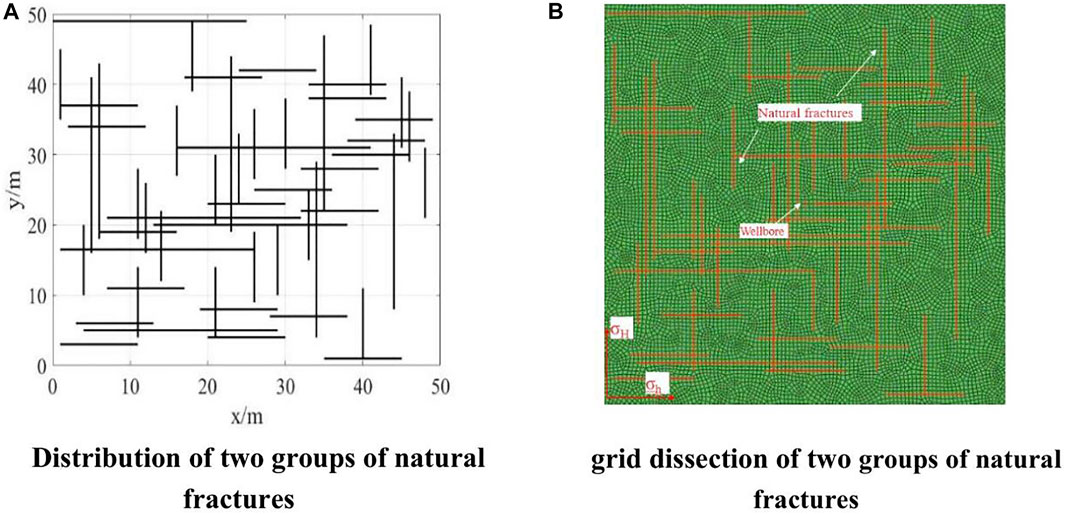
FIGURE 4. The natural fracture distribution and grid dissection. (A) Distribution of two groups of natural fractures. (B) grid dissection of two groups of natural fractures.
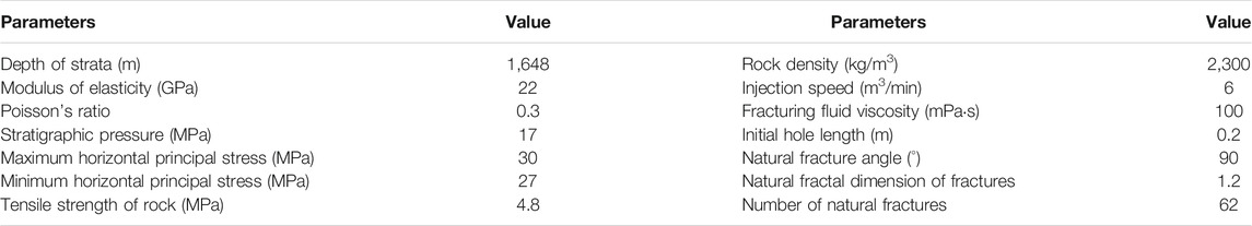
TABLE 1. Numerical simulation parameters of hydraulic fracturing in multi-fractured reservoirs.
Dynamic propagation model analysis of the fractured reservoir is used to obtain the stress distribution and fracture morphology at different time steps, as shown in Figure 5.
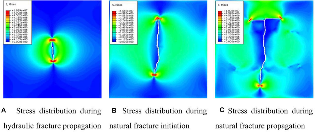
FIGURE 5. Fracture propagation pattern at different time steps (A) Stress distribution during hydraulic fracture propagation. (B) Stress distribution during natural fracture initiation. (C) Stress distribution during natural fracture propagation.
Figure 5A shows the hydraulic fracture propagation stage. The influence of natural fractures is not apparent and the fractures extend along the direction of the maximum principal stress. Figure 5B shows the propagation of the hydraulic fractures to the natural fracture boundary, which vertically intersects the natural fractures. The hydraulic fracture is captured by the natural fractures, and the fractures extend along the natural fracture direction. Figure 5C shows when the hydraulic fracture propagation meets the natural fractures and forms multiple fracture branches in three directions. The fracture propagation direction is mainly influenced by the natural fracture distribution, and the fracture complexity increases compared with a group of naturally fractured reservoirs.
Figure 6A shows that the hydraulic fractures form wider fractures near the borehole, whereas those at the end of the fracture are narrower. Figure 6B shows that hydraulic fracturing alters the in-situ stress field around the fracture. The stress field is also significantly deflected, which significantly influences the fracture propagation. Fracture propagation causes strain in the rock around the fracture (Figure 6C), and the displacement is larger near the borehole and smaller at the end of the fracture.
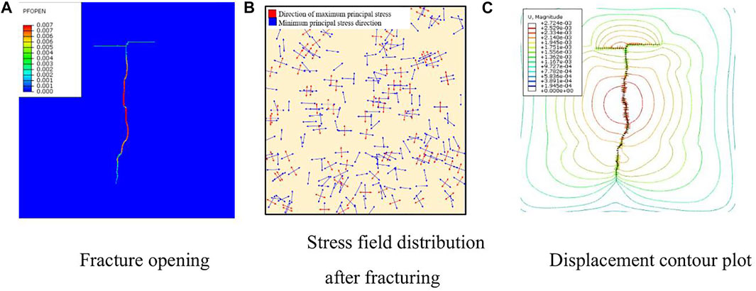
FIGURE 6. The results of simulation. (A) Fracture opening. (B) Stress field distribution after fracturing. (C) Displacement contour plot.
The distribution of real natural fractures is complex, and hydraulic fracture propagation patterns differ when encountering different natural fracture networks. Combined with the natural fracture network model (Diguang et al., 2016), a hydraulic fracture propagation model is established for the case when two sets of natural fractures exist in a reservoir. The factors that influence the fracture propagation pattern are analyzed when a single well is hydraulically fractured.
The natural fracture network model is applied to form a randomly distributed natural fracture pattern with fracture angles of 0°, 45°, and 90° and a fractal dimension of 1.2. The numerical simulation method with globally embedded cohesion units is applied to simulate and analyze the fracture propagation law in fractured reservoirs with different distributions of natural fracture angles, and the simulation results are shown in Figure 7.
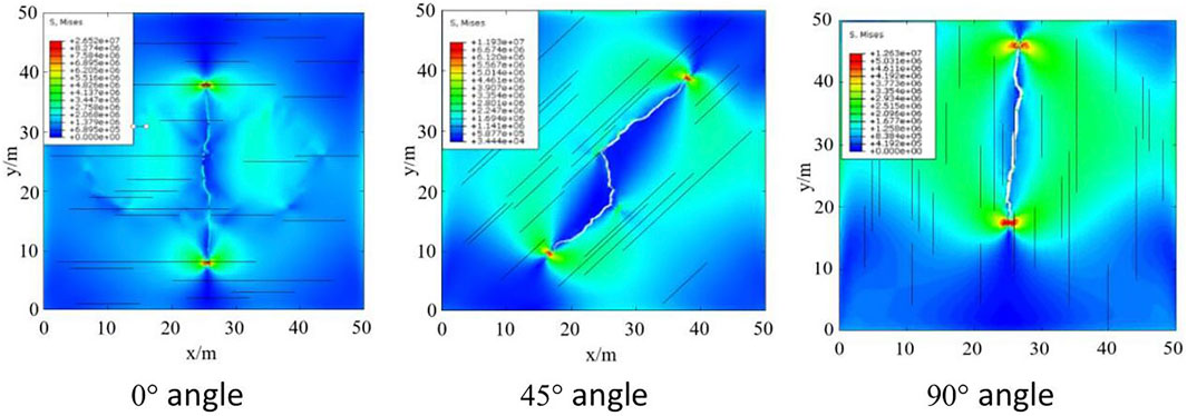
FIGURE 7. Hydraulic fracture propagation pattern of different natural fracture angle.</b>0° angle.45° angle.90° angle.
The fracture propagation pattern of the reservoir with a natural fracture distribution shows that a single fracture forms when the fracture angle is 0° or 90° and extends along the direction of the maximum horizontal principal stress. For a 0° fracture, the hydraulic fracture vertically intersects and easily crosses the natural fracture, which is controlled by the anisotropy of the stress field, and forms a more symmetrical hydraulic fracture. For a 45° fracture, the hydraulic fracture communicates with the natural fractures to form a fracture pattern that expands along the 45° direction and is less affected by the stress field anisotropy. For a 90° fracture, when the hydraulic fracture intersects with the natural fracture, the hydraulic fracture expands along the natural fracture direction. When the natural fracture is communicated, the pressure drops and the hydraulic fracture tends to expand in the direction of the pressure drop, which forms an asymmetrically expanding fracture pattern.
The fracture morphology form by hydraulic fracturing in reservoirs are compared in Figure 8 for different natural fracture angles. The results show that when the natural fracture angle is 90°, the number of natural fractures and connected natural fractures are less and the fracture width is larger. When the natural fracture angle is 45°, the hydraulic fracture opens and communicates one natural fracture. When the natural fracture distribution is 0°, the hydraulic fracture opens and communicates five natural fractures. and the propagation width increase uniformly, and fluctuations occur in the growth curve because of certain resistances when passing through the natural fracture.
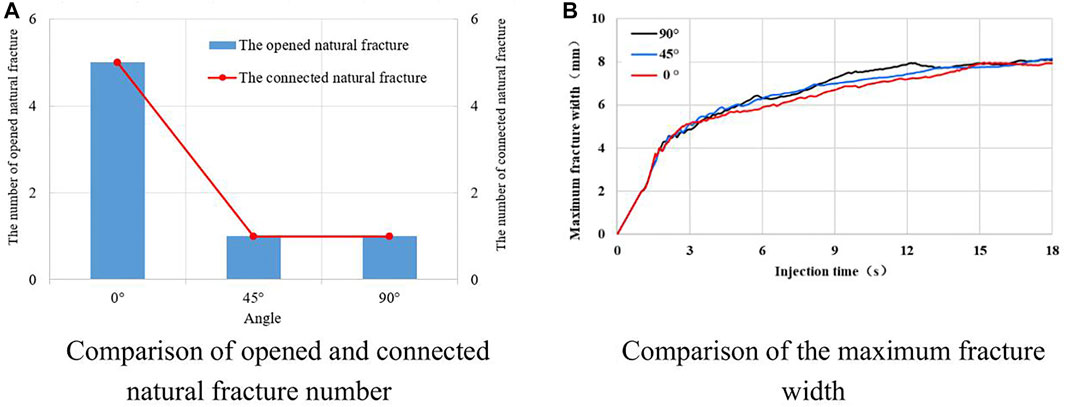
FIGURE 8. The fracture morphology comparison of different natural fracture angle. (A) Comparison of opened and connected natural fracture number. (B) Comparison of the maximum fracture width.
The natural fracture network model is applied to generate a fractal dimension of 1.2 using 1, 2, or 3 groups of natural fractures in the reservoir. The maxium number of natural fracture is 30 every group. The maxium length is 50 m and the factal dimension is 1.2. The fracture angle of the first group is 0°, the fracture angle of the second group is 90° and the fracture angle of third group is 45°. The simulations are analyzed using the globally embedded cohesion unit method, and the results are shown in Figure 9.
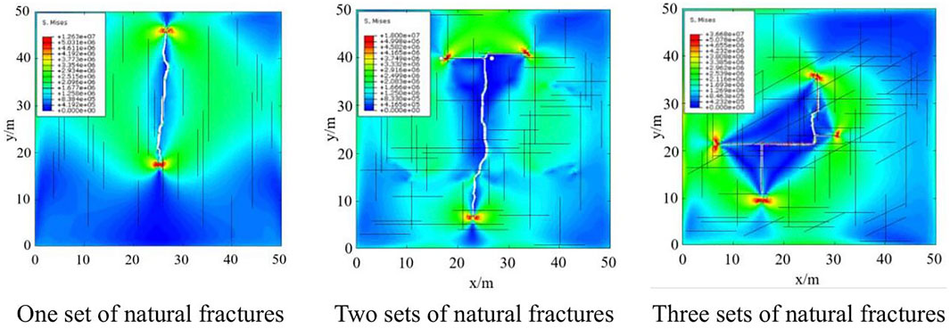
FIGURE 9. Hydraulic fracture propagation pattern of different natural fracture group. One set of natural fractures. Two sets of natural fractures. Three sets of natural fractures.
The fracture propagation morphology shows that when a group of natural fractures exists in the reservoir, the hydraulic fracture propagation morphology is singular and influenced by the stress field anisotropy. As the distribution direction of natural fractures in a reservoir increases, the hydraulic fracture propagation morphology becomes increasingly complex and forms multiple branching fractures, which are less influenced by the stress field.
Figure 10A compares the total of natural fractures that open and connect by hydraulic fracturing in reservoirs with different numbers of fracture groups. When the natural fracture group is one, the hydraulic fracture opens and connects 1 natural fracture. When the natural fracture group is two, the hydraulic fracture opens 3 natural fracture and connects 53 natural fractures. When the natural fracture group is three, the hydraulic fracture opens 5 natural fracture and connects 70 natural fractures. It can be seen that when the natural fracture is more complex, the number of opening and connecting natural fractures is more. The complex natural fractures are conducive to improve oil and gas recovery.
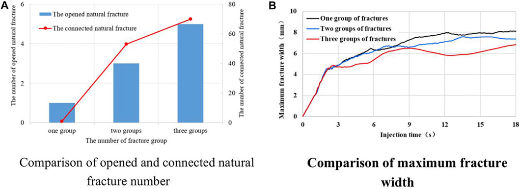
FIGURE 10. The fracture morphology comparison of different natural fracture group. (A) Comparison of opened and connected natural fracture number. (B) Comparison of maximum fracture width.
Figure 10B compares the maximum fracture widths that form by the propagation of hydraulic fracture in reservoirs with different numbers of fracture groups. The fracture widths are the same during the early propagation stage. Upon meeting natural fractures, the hydraulic fractures are affected differently because of different lengths and widths of the natural fractures. Fewer natural fracture groups tend to form larger fracture widths at a given injection time. Wide and short fractures tend to form when a single group of fractures is present in the reservoir, whereas narrow and long fractures tend to form when multiple groups of fractures are present in the reservoir.
A comparison of the obtained fracture distributions shows that an increasing number of natural fracture groups results in more complex and lower maximum fracture width, and more fracture propagation directions. The hydraulic fractures are more likely to expand along the natural fractures and form a complex fracture network, and the fracture transformation effect is better.
The fractal dimension of natural fractures is an important parameter that can be used to characterize the fracture distribution. The maxium number of natural fracture is 30, the maxium length is 50 m and the factal dimension is 1.2 in model I. The maxium number of natural fracture is 60, the maxium length is 50 m and the factal dimension is 1.4 in model Ⅱ. The maxium number of natural fracture is 110, the maxium length is 50 m and the factal dimension is 1.6 in model Ⅲ. In every model, the fracture angle of first group is 0° and the fracture angle of second group is 90°. The globally embedded zero-thickness cohesive unit method is applied to simulate the hydraulic fracture propagation process and compare and analyze the effects of fracture modification in the reservoir for different fractal dimension distributions. The simulation results are shown in Figure 11.
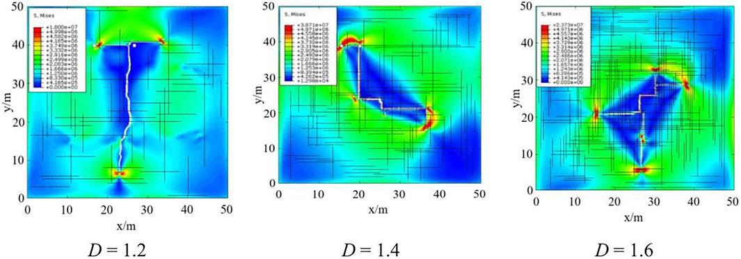
FIGURE 11. Hydraulic fracture propagation pattern of different natural fracture dimension. D = 1.2. D = 1.4. D = 1.6.
The fracture propagation morphology shows that when the fractal dimension is 1.2, the hydraulic fracture propagation morphology is singular and influenced by the stress field anisotropy. With increasing fractal dimension, the natural fracture distribution becomes increasingly complex and the hydraulic fracture propagation process leads to turning, branching, merging, and the formation of multiple branching fractures, which are less influenced by the stress field.
Figure 12 shows that once the injection energy reaches a certain value, the total fracture propagation length and width increase with increasing injection time. During the early hydraulic fracture propagation stage, the total fracture width grow at relatively consistent rates because they are not yet influenced by natural fractures. When the fractures meet natural fractures, the fracture width decreases for higher fractal dimension conditions, and the fracture propagation length tends to fluctuate. Reservoirs with a higher fractal dimension tend to open more natural fractures, fracturing fluid flows in multiple directions, less liquid exists in the main flow channel, and narrow and long natural fractures easily form that expand in multiple directions. When a hydraulic fracture expands along a natural fracture, the fracturing fluid velocity increases and the total fracture width decreases. When a hydraulic fracture expands through a natural fracture, it accumulates more energy and the fracture width rapidly increases.
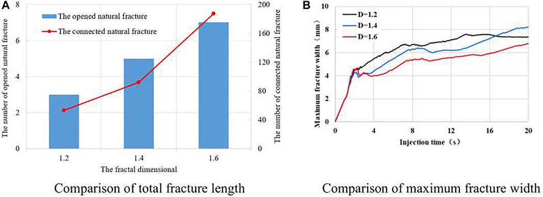
FIGURE 12. The fracture morphology comparison of different natural fracture dimension. (A) Comparison of total fracture length. (B) Comparison of maximum fracture width.
A comparison of the fracture transformation effect shows that with increasing fractal dimension, the total natural fracture that opened and connected by hydraulic fracture increases, the maximum fracture width decreases, and the number of fracture propagation directions increases. A reservoir is more likely to form a complex fracture network that expands in multiple directions after hydraulic fracturing when the fractal dimension of the natural fracture distribution is higher, and the reservoir fracture transformation effect is better compared with that prior to fracturing.
Natural fractures are the main seepage channel and important storage space of shale reservoir, and the communication of natural fractures is mainly used to improve the fracturing effect during the exploitation process. The rock outcrops is the best way to obtain the discontinuous structure such as fractures, joints. Take the outcrop of the Longmaxi formation in south Sichuan as an example to analyze the effect of hydraulic fracture technology of shale reservoir. As shown in the Figure 13, the outcrop of the measurement point develops two groups of intersecting fractures mainly. The fracture length is 0.5∼6 m, the fracture angle is 13° and 93° respectively, the fracture density is 3.26 m/m2. The nature fractures have the characteristics of grouping and parallelism. Many of the nature fractures have been broken and cleaved, and the natural fracture network is complex. Therefore, hydraulic fracturing technology is proposed to connect the complexity natural fracture and improve the oil and gas recovery.
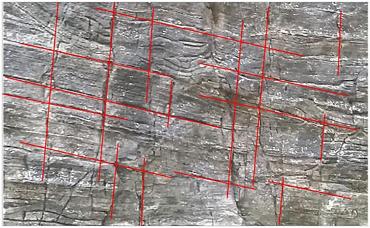
FIGURE 13. The nature fracture distribution.
In order to analyze the development characteristics of fracture network and the hydraulic fracturing effect in Longmaxi shale, MATLAB script files were used to simulate the distribution characteristics and connectivity of shale fractures according to the statistical data of shale outcrops in Longmaxi Formation. The fractal dimension of the first group is 1.6 and the fractal dimension of the second group is 1.5. The fracture angle of the first group is 13° and the fracture angle of the second group is 93°. Based on the natural fracture system, the ABAQUS was used to simulate hydraulic fracture propagation.
The natural fracture system distribution and the connectivity of the natural fracture of Longmaxi using the fracture network model is shown in Figure 14A. The connected natural fracture clusters are shown by different colors. It can be seen from that the dis-connected natural fracture account for 45.24% and the connected natural fracture account for 54.76%. The maximum connected fracture cluster contains 5 natural fractures and account for 11.90%. The hydraulic fracture process is stimulated applying the global embed cohesive elements method. The fracture morphology of this well is shown in Figure 14B. Hydraulic fracturing can connect different fracture clusters. The maximum connected fracture cluster contains 9 natural fractures and the proportion of connected fractures increased from 11.90 to 21.43% after hydraulic fracturing. The connectivity of the entire fracture and the effect of development will be greatly improved.
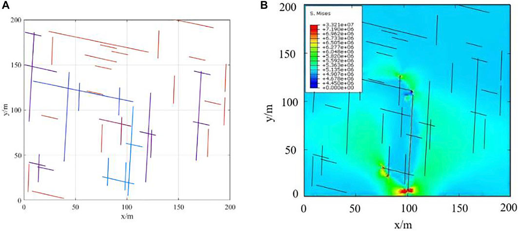
FIGURE 14. The fracture morphology before and after hydraulic fracturing. (A)The connectivity and fracture distribution of nature fracture. (B)The fracture morphology after hydraulic fracturing.
1) A dynamic hydraulic fracture propagation model is established that uses globally embedded cohesive elements and considers a reservoir with complex distributed natural fractures. The model can be used to simulate the rock and propagation behavior of hydraulic fractures and investigate the complex fracture system morphology.
2) The hydraulic fracture propagation characteristics of naturally fractured reservoirs are investigated. The hydraulic fracture propagation of fractured reservoirs is influenced by a combination of the natural fracture distribution, which determines the overall fracture propagation path direction. The fracture geometry in near-borehole areas tends to be more complex than in the far field, and the fracture size is larger.
3) The influence of different factors on the propagation of hydraulic fractures in naturally fractured reservoirs is analyzed. With increasing natural fracture angle, the hydraulic fractures easily pass through the natural fractures, the propagation form is singular, and the fractures are wider. Higher numbers of natural fracture groups tend to more readily form complex fracture forms with multiple directions, and the opened and connected natural fractures are more, and the fractures are narrow. With increasing fractal dimension, multi-directional complex fractures more easily form and the fractures are narrow, the opened and connected natural fractures are more.
4) The case study shows that connected fractures account for 54.76% of the total fractures in the outcrop shale fracture network of the Longmaxi formation and the proportion of connected fractures increased from 11.90 to 21.43% after hydraulic fracturing.
The original contributions presented in the study are included in the article/Supplementary Material, further inquiries can be directed to the corresponding author.
HZ contributed to the conception and design of the study, writing–original draft; WL contributed to the conception and funding acquisition; LW and JF contributed to the writing checking and editing; YLX and JJZ, project administration; SQL, data analysis.
The research was supported by the National Natural Science Foundation of China (No. 51774093) and Northeast Petroleum University introduces the talented person scientific research start funds subsidization project (No.13051202008).
WL and ZJ were employed by the company Daqing Oilfield Production Technology Institute.
The remaining authors declare that the research was conducted in the absence of any commercial or financial relationships that could be construed as a potential conflict of interest.
All claims expressed in this article are solely those of the authors and do not necessarily represent those of their affiliated organizations, or those of the publisher, the editors and the reviewers. Any product that may be evaluated in this article, or claim that may be made by its manufacturer, is not guaranteed or endorsed by the publisher.
Barrenblatt, G. I. (1962). The Mathematical Theory of Equilibrium Cracks in Brittle Fracture. Adv. Appl. Mech. 7, 55–125.
Bing, H., Mian, C., Baowei, Z., and Sang, Y. (2015). Propagation of Multiple Hydraulic Fractures in Fractured Shale Reservoir. Chin. J. Geotechnical Eng. 37 (6), 1041–1046. doi:10.11779/CJGE201506010
Bonnet, E., Bour, O., Odling, N. E., Davy, P., Main, I., Cowie, P., et al. (2001). Scaling of Fracture Systems in Geological media. Rev. Geophys. 39, 347–383. doi:10.1029/1999rg000074
Bour, O., and Davy, P. (1997). Connectivity of Random Fault Networks Following a Power Law Fault Length Distribution. Water Resour. Res. 33, 1567–1583. doi:10.1029/96wr00433
Bruno, G. D. S., and Einstein, H. H. (2014). Finite Element Study of Fracture Initiation in Flaws Subject to Internal Fluid Pressure and Vertical Stress. Int. J. Sol. Structures 51 (23), 4122–4136. doi:10.1016/j.ijsolstr.2014.08.006
Chen, Z., Bunger, A. P., Zhang, X., and Jeffrey, R. G. (2009). Cohesive Zone Finite Element-Based Modeling of Hydraulic Fractures. Acta Mechanica Solida Sinica 22 (5), 443–452. doi:10.1016/s0894-9166(09)60295-0
Chen, Z., Jeffrey, R., G., and Zhang, X. (2017). Finite-element Simulation of a Hydraulic Fracture Interacting with a Natural Fracture. SPE J. 22 (1), 219–234. doi:10.2118/176970-pa
Chuprakov, D. A., Akulich, A. V., and Siebrits, E. (2011). Hydraulic-fracture Propagation in a Naturally Fractured Reservoir. SPE Prod. Operations 26 (1), 88–97. doi:10.2118/128715-pa
Cottrell, M., Hosseinpour, H., and Dershowitz, W. (2013). “Rapid Discrete Fracture Analysis of Hydraulic Fracture Development in Naturally Fractured Reservoirs,” in Proceedings of the Unconventional Resources Technology Conference, Denver, CO, August 2013. doi:10.1190/urtec2013-245
Dahi, T., A., Gonzalez, M., and Hao, H. (2018). Numerical Simulation of Hydraulic Fracture Propagation in Naturally Fractured Formations Using the Cohesive Zone Model. J. Pet. Sci. Eng 165, S0920410518300755. doi:10.1016/j.petrol.2018.01.063
Dahi-Taleghani, A., and Olson, J. E. (2011). Numerical Modeling of Multistranded-Hydraulic-Fracture Propagation: Accounting for the Interaction between Induced and Natural Fractures. SPE J. 16 (03), 575–581. doi:10.2118/124884-pa
Dehghan, A. N., Goshtasbi, K., and Ahangari, K. (2016). 3D Numerical Modeling of the Propagation of Hydraulic Fracture at its Intersection with Natural (Pre-existing) Fracture. Rock Mech. Rock Eng. 50, 1–20. doi:10.1007/s00603-016-1097-7
Diguang, G., Zhanqing, Q., Jianxiong, L., and Qu, G. Z. (2016). Extended Finite Element Simulation of Hydraulic Fracture Based on ABAQUS Platform. Rock Soil Mech. 37 (5), 302–310. doi:10.16285/j.rsm.2016.05.036
Dugdale, D. S. (1960). Yielding of Steel Sheets Containing Slits. J. Mech. Phys. Sol. 8, 100–104. doi:10.1016/0022-5096(60)90013-2
Fatahi, H., Hossain, M. M., and Sarmadivaleh, M. (2017). Numerical and Experimental Investigation of the Interaction of Natural and Propagated Hydraulic Fracture. J. Nat. Gas Sci. Eng. 37, 409–424. doi:10.1016/j.jngse.2016.11.054
Fei, L., Zhifeng, L., Yu, S., and Changlin, Z. (2017). Deformation Behavior between Hydraulic and Natural Fractures Using Fully Coupled Hydromechanical Model with XFEM. Math. Probl. Eng., 1–12. doi:10.1155/2017/6373957
Gonzalez, M., and Dahi, T., A. (2015). “A Cohesive Model for Modeling Hydraulic Fractures in Naturally Fractured Formations[C],” in Proceedings of the SPE hydraulic fracturing technology conference, Woodlands, TX (Woodlands, TX: HFTC), 3–5.
Guo, J., Luo, B., Lu, C., Lai, J., and Ren, J. (2017). Numerical Investigation of Hydraulic Fracture Propagation in a Layered Reservoir Using the Cohesive Zone Method. Eng. Fracture Mech. 186, 195–207. doi:10.1016/j.engfracmech.2017.10.013
Gustafson, G., and Fransson, Å (2005). The Use of the Pareto Distribution for Fracture Transmissivity Assessment. Hydrogeol J. 14, 15–20. doi:10.1007/s10040-005-0440-y
Haddad, M., Du, J., and Vidal-Gilbert, S. (2016). “Integration of Dynamic Microseismic Data with a True 3D Modeling of Hydraulic Fracture Propagation in Vaca Muerta Shale[C],” in Proceedings of the SPE hydraulic fracturing technology conference (Woodlands, TX: HFTC), 9–11.
Haddad, M., and Sepehrnoori, K. (2015). Simulation of Hydraulic Fracturing in Quasi-Brittle Shale Formations Using Characterized Cohesive Layer: Stimulation Controlling Factors. J. Unconventional Oil Gas Resour. 9, 65–83. doi:10.1016/j.juogr.2014.10.001
Jianchun, G., Xing, Z., Haiyan, Z., and Rui, P. (2015). Numerical Simulation of Interaction of Hydraulic Fracture and Natural Fracture Based on the Cohesive Zone Finite Element Method. J. Nat. Gas Sci. Eng. 25, 180–188. doi:10.1016/j.jngse.2015.05.008
Jun, Z., Yuwei, L., Yishan, P., and Xiangyang, W. (2021). Experiments and Analysis on the Influence of Multiple Closed Cemented Natural Fractures on Hydraulic Fracture Propagation in a Tight Sandstone Reservoir. Eng. Geology. 281, 105981.
Kresse, O., Weng, X., Gu, H., and Wu, R. (2013). Numerical Modeling of Hydraulic Fractures Interaction in Complex Naturally Fractured Formations. Rock Mech. Rock Eng. 46 (3), 555–568. doi:10.1007/s00603-012-0359-2
Lei, X., Yawu, Z., Lei, Ji., and Ye, Y. (2016). Research on Influence of Initial Horizontal Principal Stress on Stress Shadow. Chin. J. Rock Mech. Eng. S1, 2819–2825. doi:10.13722/j.cnki.jrme.2015.1555
Mokryakov, V. (2011). Analytical Solution for Propagation of Hydraulic Fracture with Barenblatt's Cohesive Tip Zone. Int. J. Fract 169, 159–168. doi:10.1007/s10704-011-9591-0
Nan, Z., Tan, M., and Liu, Z. (2020). Quantitative Fracture Evaluation Method Using Microspherically Focused Logging Data. Well Logging Technology 44 (1), 61–66. doi:10.1016/j.engeos.2021.08.005
Rahman, M. M., and Rahman, M. K. (2010). A Review of Hydraulic Fracture Models and Development of an Improved pseudo-3D Model for Stimulating Tight Oil/gas Sand. Energy Sourc. A: Recovery, Utilization, Environ. Effects 32 (15), 1416–1436. doi:10.1080/15567030903060523
Tang, J., Fan, B., Xiao, L., Tian, S., Zhang, F., Zhang, L., et al. (2020). A New Ensemble Machine-Learning Framework for Searching Sweet Spots in Shale Reservoirs. SPE J. 26 (1). doi:10.2118/204224-pa
Wang, H. (2019). Hydraulic Fracture Propagation in Naturally Fractured Reservoirs: Complex Fracture or Fracture Networks. J. Nat. Gas Sci. Eng. 68, 102911. doi:10.1016/j.jngse.2019.102911
Wang, H. (2016). Numerical Investigation of Fracture Spacing and Sequencing Effects on Multiple Hydraulic Fracture Interference and Coalescence in Brittle and Ductile Reservoir Rocks. Eng. Fracture Mech. 157, 107–124. doi:10.1016/j.engfracmech.2016.02.025
Wang, H. (2015). Numerical Modeling of Non-planar Hydraulic Fracture Propagation in Brittle and Ductile Rocks Using XFEM with Cohesive Zone Method. J. Pet. Sci. Eng. 135, 127–140. doi:10.1016/j.petrol.2015.08.010
Wei, L., Huan, Z., and Hongjun, W. (2020). A Novel Approach of Two-Dimensional Representation of Rock Fracture Network Characterization and Connectivity Analysis. J. Pet. Sci. Eng. 184, 106507. doi:10.1016/j.petrol.2019.106507
Wen, R., Yang, X., and Liu, D. (2019). Comprehensive Evaluation of Fracture Distribution by Near-And Far-Well Logging and Monitoring Technology. Well Logging Technology 43 (5), 531–535. doi:10.16489/j.issn.1004-1338.2019.05.017
Xia, H., Han, L., and Li, G. (2020). New Method for Calculating Fracturing Pressure of TIV Formation in Horizontal Wells. Well Logging Technology 44 (2), 116–121.
Yang, Z. J., Su, X. T., Chen, J. F., and Liu, G. H. (2009). Monte Carlo Simulation of Complex Cohesive Fracture in Random Heterogeneous Quasi-Brittle Materials. Int. J. Sol. Structures 46 (17), 3222–3234. doi:10.1016/j.ijsolstr.2009.04.013
Yuwei, L., Dan, J., Zhenhua, R., and Jun, Z. (2017). Evaluation Method of Rock Brittleness Based on Statistical Constitutive Relations for Rock Damage. J. Pet. Sci. Eng. 153, 123–132. doi:10.1016/j.petrol.2017.03.041
Zhang, X., and Jeffrey, R. G. (2006). The Role of Friction and Secondary Flaws on Deflection and Re-initiation of Hydraulic Fractures at Orthogonal Pre-existing Fractures. Geophys. J. Int. 166 (3), 1454–1465. doi:10.1111/j.1365-246x.2006.03062.x
Zhang, X., Jeffrey, R. G., and Thiercelin, M. (2007). Deflection and Propagation of Fluid-Driven Fractures at Frictional Bedding Interfaces: A Numerical Investigation. J. Struct. Geology. 29 (3), 396–410. doi:10.1016/j.jsg.2006.09.013
Zhilong, L., Jin, Z., and Heng’an, W. (2008). A Simulation Study of Hydraulic Fracturing Propagation with a Solid-Fluid Coupling Model. Rock Soil Mech. 29 (11), 138–143.
Zhiqiang, C., Zhengming, Y., and Moran, W. (2018). Hydro-mechanical Coupled Mechanisms of Hydraulic Fracture Propagation in Rocks with Cemented Natural Fractures. J. Pet. Sci. Eng. 163, 421–434. doi:10.1016/j.petrol.2017.12.092
Keywords: complex natural fracture, hydraulic fracture, dynamic propagation, cohesive zone element, fractal dimension
Citation: Zhao H, Li W, Wang L, Fu J, Xue YL, Zhu JJ and Li SQ (2022) The Influence of the Distribution Characteristics of Complex Natural Fracture on the Hydraulic Fracture Propagation Morphology. Front. Earth Sci. 9:784931. doi: 10.3389/feart.2021.784931
Received: 28 September 2021; Accepted: 29 November 2021;
Published: 31 January 2022.
Edited by:
Jizhou Tang, Tongji University, ChinaReviewed by:
Jiawei Li, Texas A&M University, United StatesCopyright © 2022 Zhao, Li, Wang, Fu, Xue, Zhu and Li. This is an open-access article distributed under the terms of the Creative Commons Attribution License (CC BY). The use, distribution or reproduction in other forums is permitted, provided the original author(s) and the copyright owner(s) are credited and that the original publication in this journal is cited, in accordance with accepted academic practice. No use, distribution or reproduction is permitted which does not comply with these terms.
*Correspondence: Wei Li, bGl3ZWlAbmVwdS5lZHUuY24=
Disclaimer: All claims expressed in this article are solely those of the authors and do not necessarily represent those of their affiliated organizations, or those of the publisher, the editors and the reviewers. Any product that may be evaluated in this article or claim that may be made by its manufacturer is not guaranteed or endorsed by the publisher.
Research integrity at Frontiers
Learn more about the work of our research integrity team to safeguard the quality of each article we publish.