
94% of researchers rate our articles as excellent or good
Learn more about the work of our research integrity team to safeguard the quality of each article we publish.
Find out more
ORIGINAL RESEARCH article
Front. Earth Sci., 17 November 2021
Sec. Solid Earth Geophysics
Volume 9 - 2021 | https://doi.org/10.3389/feart.2021.783409
This article is part of the Research TopicSubduction and Collision Dynamics of Tectonic PlatesView all 15 articles
The geometries of trenches vary worldwide due to continuous plate boundary reorganization. When two trenches intersect to generate a corner, a subduction cusp is formed. Although subduction cusps are frequently observed throughout historical plate movement reconstructions, few studies have been conducted to explore the controlling factors of trench migration and slab morphology along subduction cusps. Here, we use a 3-D dynamic subduction model to explore the influence of the overriding plate strength, initial slab-pull force, and initial cusp angle on the evolution of subduction cusps. Our numerical model results suggest the following: 1) subduction cusps have a tendency to become smooth and disappear during the subduction process; 2) the slab dip angle is smallest in the diagonal direction of the subduction cusp, and a larger cuspate corner angle leads to a larger slab dip angle; 3) the asymmetric distribution of the overriding plate strength and initial slab-pull force determine the asymmetric evolutionary pathway of subduction cusps. Our results provide new insights for reconstructing the evolution of subduction cusps from seismological and geological observations.
During the evolution of plate tectonics, trenches located at the junction of subducting and overriding plates can develop various kinds of geometries (Schellart et al., 2007; Müller et al., 2016). When two trenches intersect with each other to form a corner, we define it as a subduction cusp. For example, at 40 Ma, the trenches along the Kurile Islands and northeast Japan intersected and formed a subduction cusp (Figure 1A) (Vaes et al., 2019). At 35 Ma, the Pacific plate subducted beneath the Eurasian and Philippine Sea plates, and the trenches along the Eastern Japan and Izu-Bonin arc were generally perpendicular to each other, forming a subduction cusp (Figure 1D) (Hall, 2002; Ma et al., 2019).
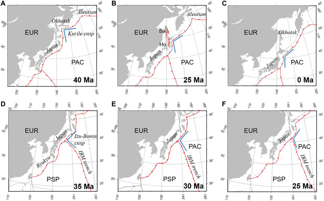
FIGURE 1. (A), (B), and (C) show the plate boundary configurations near the Kurile Islands at (A) 40 Ma, (B) 25 Ma, and (C) 0 Ma (after Vaes et al., 2019). (D), (E), and (F) show plate reconstruction results near the Philippine Sea plate at (D) 35 Ma, (E) 30 Ma, and (F) 25 Ma (after Müller et al., 2016). Red lines with filled triangles and arrows represent trenches and strike-slip faults, respectively. The Kurile and Izu-Bonin cusps are represented by blue angles. Abbreviations: PAC = Pacific plate; EUR = Eurasian plate; PSP = Philippine Sea plate; Sa = Sakhalin; and Ho = Hokkaido.
Subduction cusps can be generated under various tectonic settings. For example, a series of numerical models and analog models have shown that a subduction cusp can be formed by aseismic ridge or plateau subduction (Martinod et al., 2005; Martinod et al., 2013; Zeumann and Hampel, 2016). It is possible that the cusps linking the Kurile Islands and northeast Japan trenches and the Izu-Bonin arc and East Japan trenches (Figure 1) were generated by the subduction of oceanic plateaus that have since been entirely consumed (Rosenbaum and Mo, 2011).
Once a subduction cusp is formed, its evolutionary pathway is of particular interest in terms of trench migration and slab morphology. The evolution of the Kurile cusp and Izu-Bonin cusp has some common features regarding their trench migration. At 40 Ma, the angle between the trenches along northeast Japan and the Kurile Islands was ∼90° (Figure 1A). Then, the trench along the Kurile Islands began to retreat and rotate counterclockwise, forming a dextral strike-slip fault between Sakhalin and central Hokkaido (Figure 1B). After that, the trench along northeast Japan began to retreat at approximately 25 Ma. The retreat of these two trenches facilitated the opening of the Kurile and Japan Sea basins. The trench retreated faster at the subduction cusp, causing an increasing angle between these two trenches (Figures 1A–C) (Vaes et al., 2019). Similarly, at 35 Ma, the Pacific plate subducted beneath the Philippine Sea plate and East Asian margin. The trenches along these two overriding plates were almost perpendicular to each other (Figure 1D). The Philippine Sea plate moved northward and rotated clockwise, with the subduction of the Pacific plate, thereby forcing the triple junction (between the Pacific plate, Philippine Sea plate and Eurasian plate) to move northeastward, and the angle between the Izu-Bonin arc and Japan trench gradually became larger (Figures 1D–F) (Hall, 2002; Ma et al., 2019).
The Kurile cusp and Izu-Bonin cusp also show similar characteristics in slab morphology. From seismic tomography results, we can find that the slab dip angle varies along these two subduction zones and reaches its minimum beneath the cuspate area (Miller and Kennett, 2006; Zhang et al., 2019). Along the Kurile trench, the subducting slab steepens gradually from the cuspate area to the northeast Kurile and Kamchatka (Miller and Kennett, 2006), and the slab dip angle along the Izu-Bonin subduction zone increases southward (Zhang et al., 2019). Such variations in slab dip angle have formed a unique slab morphology beneath the Kurile Islands and Izu-Bonin arc. Part of the subducting slab penetrates into the lower mantle through the mantle transition zone, while other parts of the slab remain stagnant in the mantle transition zone (Torii and Yoshioka, 2007; Zhao et al., 2012; Zhang et al., 2019).
The 3-D evolution of subduction zones has been studied before using numerical models. For example, Bengtson and van Keken (2012) and Kneller and van Keken (2008) used a 3-D subduction model to investigate the influence of slab geometries on mantle flow, shear wave anisotropy, and temperature structure. Morishige and Honda (2013) focused on the influence of rheology on mantle flow, slab morphology and seismic anisotropy in a subduction model with a triple junction. However, few studies have investigated the evolution of subduction cusps and related trench migration patterns and slab morphologies.
In this paper, we explore the evolution of subduction cusps using a 3-D dynamic subduction model. In particular, we systematically investigate the controlling effects of the overriding plate strength, initial slab-pull force, and initial cusp angle on trench migration and slab morphology in subduction cusps.
To investigate the trench migration process and slab morphology of subduction cusps, a 3-D dynamic subduction model is developed. Leng and Gurnis (2015) modified CitcomCU (Zhong, 2006) by adding viscoelastic and material tracking methods. Our calculation method follows Leng and Gurnis (2015) to solve the mass, momentum, and energy conservation equations. Here, only the basic model setup and material rheology are introduced. For more details on the methodology, please refer to Leng and Gurnis (2011) and Leng and Gurnis (2015).
The model domain is 660 km deep, 2,970 km wide and 2,970 km in length. The “particle in cell” method makes it possible to calculate a 3-D numerical model with a relatively low resolution. We use a uniform grid of
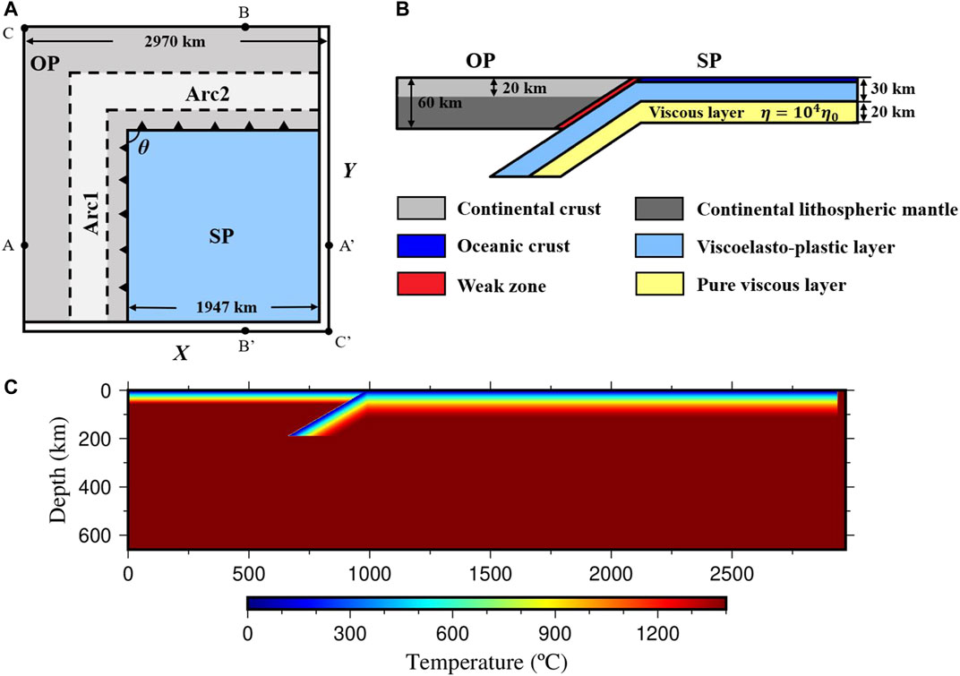
FIGURE 2. (A) Top view of our geodynamic model, including a subducting oceanic plate and an overriding continental plate. We select profiles
We impose isothermal boundary conditions with a fixed temperature at 0°C at the top boundary and 1,400°C at the bottom ignoring adiabatic heating. A half-space cooling model with an age of 60 Ma is imposed as the initial temperature field of the subducting plate, and a linear temperature field is employed on the overriding continental plate (Figure 2C). The influences of the subducting plate age and overriding plate thickness on subduction dynamics have been discussed previously (Holt et al., 2015; Agrusta et al., 2017). A thick overriding plate prevents trench retreat and has the tendency to develop a large slab dip angle (Holt et al., 2015), whereas old plate subduction promotes trench retreat and usually develops a small slab dip angle, leading to a stagnant slab in the mantle transition zone (Agrusta et al., 2017). Therefore, we fix the overriding plate thickness to 60 km and the subducting plate age to 60 Ma in our model. We apply free-slip boundary conditions to all model boundaries.
An incompressible Maxwell body is used to describe the viscoelasticity of the material in our model. The following equation is employed to calculate the contribution of viscous and elastic components to the strain rate (Moresi et al., 2002):
where
where
The yielding stress,
where
where
We first run a reference case_ref (Table 2), with two weak arc regions (Arc1 and Arc2) in the overriding continental plate. The weak region is 297 km wide and 165 km away from the trench (Figure 2A). The tip of the subducting slab is bent to reach a depth of 165 km, which can provide enough initial slab-pull force to initiate subduction.
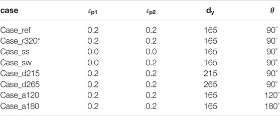
TABLE 2. Parameter values for cases in this study.
At the beginning of the subduction process, the tip of the subducting slab changes its dip angle from 30° to nearly 90°, and the subducting plate begins to move slowly trenchward due to a relatively small slab-pull force (Figure 3A). Then, as the subduction process continues, the subducting plate begins to accelerate, reaching the bottom boundary of the model domain after 8.83 million years (Myr) of subduction (Figure 3B). Finally, the subducting slab stagnates on the bottom boundary after 13.25 Myr (Figure 3C). The subducting slab develops different dip angles in different directions. Here, we select profiles
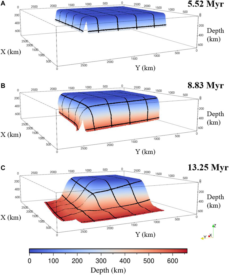
FIGURE 3. The evolution of slab morphology at 5.52 (A), 8.83 (B), and 13.25 (C) Myr in the reference model. The color indicates the depth of the slab. We put some black tracking lines on the slab surface to better display the three-dimensional structure of the slab.
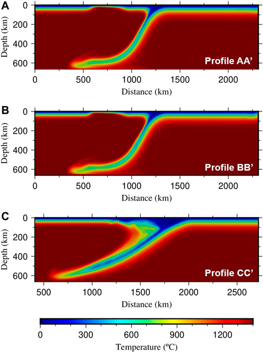
FIGURE 4. Temperature field along the profiles of
We placed tracking tracers at the end of the subducting plate (66 km away from the plate edge) to obtain its velocity. Figure 5A shows that the subducting velocity (red lines in Figure 5A) is almost the same in the
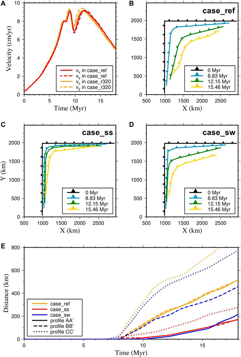
FIGURE 5. (A) The velocities of the subducting plate in the
Resolution test has been made to determine the proper resolution required to resolve the subduction zone accurately (case_r320 in Table 2). The results show that the velocities of subducting plate are very comparable for a resolution of 256
The overriding plate is relatively weak due to the existence of weak arc regions in the reference model. Previous 2-D studies have shown that the overriding plate strength has great influences on subduction dynamics (Garel et al., 2014; Holt et al., 2015; Yang et al., 2018). Here, we investigate the influence of the asymmetry of the weak arc region on the evolution of subduction cusps (case_sw and case_ss in Table 2). In our reference model case_ref, the overriding plate is weak in both the Arc1 and Arc2 regions (Figure 2A). In case_sw, only the Arc2 region is weak, whereas in case_ss, both weak arc regions are removed.
Figure 5C–E shows the influence of the overriding plate strength on the trench retreat process. Figures 5C, D show the evolution of trench geometries in case_ss and case_sw, respectively. In case_ss, the trench retreats slightly in the diagonal direction, changing the sharp subduction cusp to a gentle curvature locally. Nevertheless, the trench positions are generally stable in both the
Figure 6 shows the morphology of the subducting slab in the
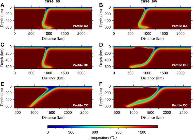
FIGURE 6. Temperature field along the profiles of
The slab-pull force is considered to be the main driving force behind subduction (Schellart, 2004). Here, we change the initial length of the bending tip of the subducting slab to control the initial slab-pull force (case_d215 and case_d265 in Table 2). A longer bending tip of the subducting slab provides a larger slab-pull force. In the reference case_ref, the tip of the subducting slab reaches 165 km depth beneath both the Arc1 and Arc2 regions. For the cases of case_d215 and case_d265, we keep the slab tip at 165 km depth beneath the Arc1 region but increase the slab tip to 215 and 265 km depths beneath the Arc2 region.
Figure 7A shows the influence of the initial slab-pull force on the velocities of the subducting plate in the
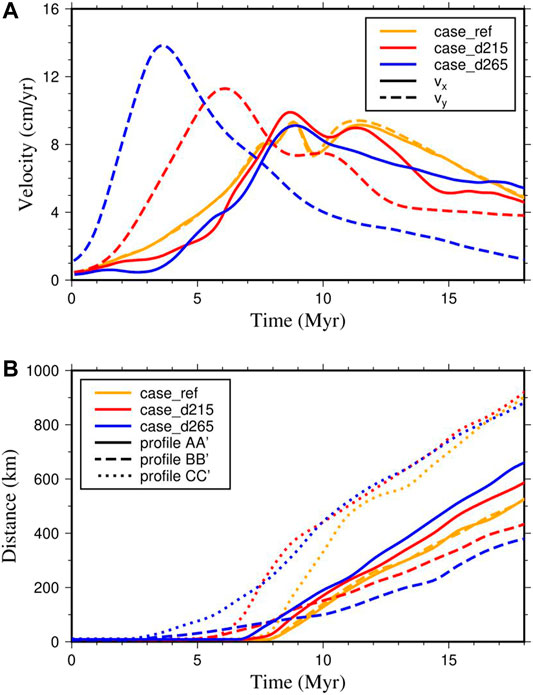
FIGURE 7. (A) The velocities of the subducting plate in case_ref (orange), case_d215 (red), and case_d265 (blue). The solid line and dashed line represent the velocities of the subducting plate in the
Figure 7B shows the influence of the initial slab-pull force on trench migration. When the initial slab-pull force in the
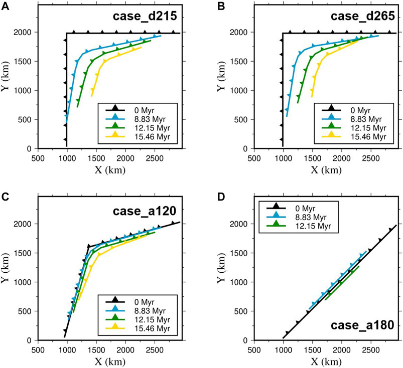
FIGURE 8. Trench migration history in case_d215 (A), case_d265 (B), case_a120 (C), and case_a180 (D).
In the previous cases, the slab dip angle remains smallest in the diagonal direction, even for case_ss, in which the trench retreats a very limited distance (Figures 5C) and (Figure 6E). Therefore, the overriding plate strength and the initial slab-pull force cannot be the key controlling factors driving the slab dip angle in the diagonal direction. On the other hand, the initial cusp angle may play important roles in the resulting slab morphology. We run case_a120 and case_a180 with different initial cusp angles of 120° and 180° to test this point (Table 2).
With increasing initial cusp angles, the subducting plate becomes smaller. The subduction process continues for only ∼12 Myr in case_a180 (Figure 8D). Comparing case_ref, case_a120, and case_a180 (Figures 5B) and (Figures 8C,D), it can be observed that the trench only retreats insignificantly when the initial cusp angle is large. When the initial cusp angle becomes smaller than 120°, the trench retreat distance in the diagonal direction increases drastically (Figures 5B) and (Figures 8C,D). Therefore, a smaller cusp angle leads to a faster trench retreat in the diagonal direction, which eventually smooths and destroys the cusp. Figure 9 shows the slab dip angle in the diagonal direction for case_ref, case_a120, and case_a180. With increases in the initial cusp angle from 90° to 120° and 180°, the slab dip angle in the diagonal direction increases from ∼30° to ∼45° and ∼90°. Thus, a larger cuspate corner angle causes a larger slab dip angle.
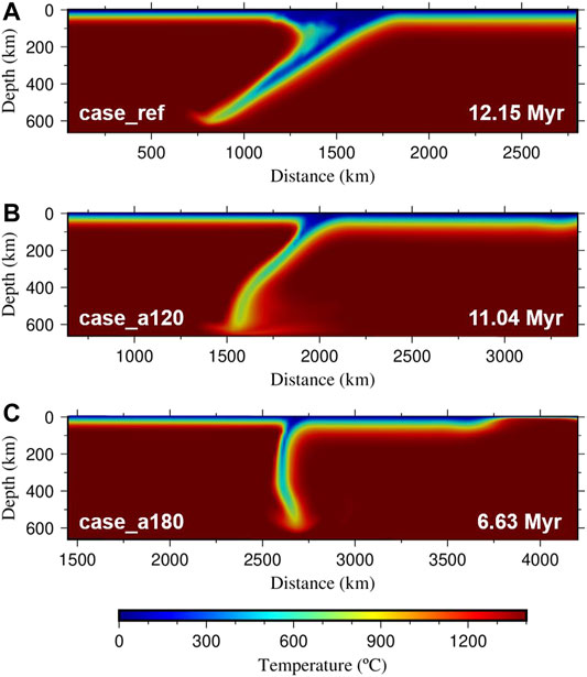
FIGURE 9. Temperature field along profile
Plate reconstruction results suggest that the Pacific plate began to subduct beneath Kurile and Japan at ∼60 Ma, following the subduction of the Izanagi plate (Figure 1A) (Müller et al., 2016; Vaes et al., 2019). The cuspate corner angle at the Kurile Islands was approximately 90° at 40 Ma and it became increasingly larger during the subduction of the Pacific plate (Figures 1A–C), which is consistent with our model results (Figures 5B–D). The trench along the Kurile Islands retreated faster near the cuspate corner, developing a wedge-shaped extensional basin in the back-arc area (Schellart et al., 2003), which is also in high agreement with the results of our model (Figures 8A,B). The morphology of the subducting slab beneath the Kurile Islands can be obtained from seismic tomography results. Our results show that the slab dip angle is smallest in the diagonal direction and becomes increasingly larger toward two lateral edges when the initial cusp angle is relatively small (Figure 3). Seismic tomography shows similar results beneath the Kurile Islands in which the slab dip angle is small beneath the cuspate corner area and becomes larger northeastward (Miller and Kennett, 2006).
One interesting observation for the Kurile cusp is that the retreat distance of the Kurile trench is larger than that along the northeast Japan trench, suggesting asymmetric subduction. Both the overriding plate strength and initial slab-pull force may cause asymmetric cusp subduction (Figure 5D) and (Figure 8A). Many geological observations suggest that the overriding Okhotsk and northeast Japan plates both experienced extensive tectonic events before the subduction of the Pacific plate (Itoh et al., 2019; Vaes et al., 2019); therefore, the strength of both plates were likely weak. As a result, the asymmetric subduction of the Kurile cusp may have been caused by different initial slab-pull forces. According to the results of our model, we suggest that the initial slab-pull force beneath northeast Japan is larger than that beneath the Kurile Islands. After the Izanagi plate subducted beneath the Eurasian plate, the Pacific plate began to subduct, and the two plates broke up at the mid-ocean ridges (Thorkelson, 1996; Seton et al., 2015). If the plates broke earlier beneath northeast Japan, the early subduction of the Pacific plate would have caused a larger slab-pull force beneath northeast Japan than beneath the Kurile Islands.
At the Izu-Bonin cusp, the trench migration history and slab morphology are similar to those of the Kurile cusp. The angle of the cuspate corner changed from ∼90° to ∼120° between 35 Ma and 25 Ma (Figures 1D–F). The Izu-Bonin trench retreated faster near the cuspate corner and formed a wedge-shaped extensional basin in the back-arc region on the Philippine Sea plate (Hall, 2002; Ma et al., 2019). Seismic tomography results show that the slab dip angle becomes larger southward (Zhang et al., 2019). In our model, the overriding plate is a continental plate that is different from the Izu-Bonin cusp. Nevertheless, the Philippine Sea plate is a young oceanic plate, which is presumably weaker than a weak continental plate. Thus, based on our model results, it is reasonable to assume that the Izu-Bonin trench retreats dominantly due to a weak overriding plate.
Aside from the Kurile and Izu-Bonin cusps, we can find another cusp located at Solomon Sea in plate tectonic history. The Pacific plate was subducting beneath Philippine Sea plate and Solomon Sea plate, and the cusp angle became smaller continuously between 35 Ma and 20 Ma (Zahirovic et al., 2014; Seton et al., 2016). There are many other cusps on the Earth’s surface, such as the Kamchatka cusp and Alaskan cusp, whose cusp angles have remained small during the last several million years (Müller et al., 2016). These cusps have strong correlations to the subduction of aseismic ridges or buoyant blocks (Rosenbaum and Mo, 2011). At the Kamchatka cusp, the Hawaii-Emperor seamount trail subducts beneath the overriding continental plate, possibly causing a subduction cusp at the collision area. The angle of the cuspate corner remains small at the Gulf of Alaska, where the collision of the Yakutat block and Kodiak and Cobb seamount trails occurs (Mazzotti and Hyndman, 2002; Rosenbaum and Mo, 2011). Comparing the Kamchatka and Alaskan cusps with the Kurile and Izu-Bonin cusps, it should be noted that the ongoing subduction of buoyant seamount trails beneath the Kamchatka and Alaskan cusps corresponds to small cusp angles, whereas the Kurile and Izu-Bonin cusps have a tendency to become smooth and disappear. Thus, we can speculate that the subduction process of aseismic ridges or buoyant blocks causes the formation of subduction cusps. Once the subduction of aseismic ridges or buoyant blocks terminates, the subduction cusp tends to be smooth and disappear, as shown in our model results.
In previous 2-D studies, it has been proposed that trench retreat can strongly influence the dip angle of subducting slabs (Agrusta et al., 2017). When the trench retreats fast, the subducting slab has a small dip angle. When the trench retreats slowly, it is difficult for the subducting slab to incline, and it prefers to subduct vertically with a large slab dip angle. Here, in our 3-D subduction cusp model, we can see from Figure 5C and Figure 6 that the trench retreating distance is limited in case_ss, but the slab dip angle is still small in the diagonal direction, showing that the 3-D effects of a subduction cusp are important for slab geometry.
Here, we did not include the lower mantle in our model for computational efficiency. Since both the viscosity jump and endothermic phase transition at a depth of 660 km could make the slab stagnate in the mantle transition zone (Torii and Yoshioka, 2007; Yoshida, 2013; Agrusta et al., 2017), such a simplification is probably reasonable. Nevertheless, a larger box with a lower mantle included is helpful for future studies of subduction cusp evolution. Moreover, our model results show that the slab dip angle in the diagonal direction is the smallest compared with that in the
In summary, using a 3-D dynamic subduction model, we investigate the influence of overriding plate strength, initial slab-pull force, and initial cusp angle on slab morphology and trench migration of subduction cusps. Following conclusions are obtained:
Subduction cusps have the tendency to become smooth and disappear during the subduction process.
The slab dip angle is the smallest in the diagonal direction of subduction cusps, and a larger cuspate corner angle leads to a larger slab dip angle.
The asymmetric distribution of the overriding plate strength and initial slab-pull force determines the asymmetric evolutionary pathway of subduction cusps.
The raw data supporting the conclusion of this article will be made available by the author, without undue reservation.
HZ and WL contributed to conception and design of this study. XS found plate reconstruction data and plot them. HZ wrote the first draft of the manuscript. All authors contributed to manuscript revision, read, and approved the submitted version.
This work is supported by the National Natural Science Foundation of China (41774105, 41820104004, 41688103) and the Fundamental Research Funds for the Central Universities (WK2080000144).
The authors declare that the research was conducted in the absence of any commercial or financial relationships that could be construed as a potential conflict of interest.
All claims expressed in this article are solely those of the authors and do not necessarily represent those of their affiliated organizations, or those of the publisher, the editors and the reviewers. Any product that may be evaluated in this article, or claim that may be made by its manufacturer, is not guaranteed or endorsed by the publisher.
Agrusta, R., Goes, S., and van Hunen, J. (2017). Subducting-slab Transition-Zone Interaction: Stagnation, Penetration and Mode Switches. Earth Planet. Sci. Lett. 464, 10–23. doi:10.1016/j.epsl.2017.02.005
Bengtson, A. K., and van Keken, P. E. (2012). Three-dimensional thermal Structure of Subduction Zones: Effects of Obliquity and Curvature. Solid Earth 3 (2), 365–373. doi:10.5194/se-3-365-2012
Garel, F., Goes, S., Davies, D. R., Davies, J. H., Kramer, S. C., and Wilson, C. R. (2014). Interaction of Subducted Slabs with the Mantle Transition‐zone: A Regime Diagram from 2‐D Thermo‐mechanical Models with a mobile Trench and an Overriding Plate. Geochem. Geophys. Geosyst. 15 (5), 1739–1765. doi:10.1002/2014gc005257
Hall, R. (2002). Cenozoic Geological and Plate Tectonic Evolution of SE Asia and the SW Pacific: Computer-Based Reconstructions, Model and Animations. J. Asian Earth Sci. 20 (4), 353–431. Article Pii s1367-9120(01)00069-4. doi:10.1016/s1367-9120(01)00069-4
Holt, A. F., Becker, T. W., and Buffett, B. A. (2015). Trench Migration and Overriding Plate Stress in Dynamic Subduction Models. Geophys. J. Int. 201 (1), 172–192. doi:10.1093/gji/ggv011
Itoh, Y., Wang, K., Nishimura, T., and He, J. (2019). Compliant Volcanic Arc and Backarc Crust in Southern Kurile Suggested by Interseismic Geodetic Deformation. Geophys. Res. Lett. 46 (21), 11790–11798. doi:10.1029/2019gl084656
Kneller, E. A., and van Keken, P. E. (2008). Effect of Three-Dimensional Slab Geometry on Deformation in the Mantle Wedge: Implications for Shear Wave Anisotropy. Geochem. Geophys. Geosyst. 9, a–n. Article Q01003. doi:10.1029/2007gc001677
Leng, W., and Gurnis, M. (2011). Dynamics of Subduction Initiation with Different Evolutionary Pathways. Geochem. Geophys. Geosyst. 12, a–n. Article Q12018. doi:10.1029/2011gc003877
Leng, W., and Gurnis, M. (2015). Subduction Initiation at Relic Arcs. Geophys. Res. Lett. 42 (17), 7014–7021. doi:10.1002/2015gl064985
Ma, P., Liu, S., Gurnis, M., and Zhang, B. (2019). Slab Horizontal Subduction and Slab Tearing beneath East Asia. Geophys. Res. Lett. 46 (10), 5161–5169. doi:10.1029/2018gl081703
Martinod, J., Funiciello, F., Faccenna, C., Labanieh, S., and Regard, V. (2005). Dynamical Effects of Subducting Ridges: Insights from 3-D Laboratory Models. Geophys. J. Int. 163 (3), 1137–1150. doi:10.1111/j.1365-246X.2005.02797.x
Martinod, J., Guillaume, B., Espurt, N., Faccenna, C., Funiciello, F., and Regard, V. (2013). Effect of Aseismic ridge Subduction on Slab Geometry and Overriding Plate Deformation: Insights from Analogue Modeling. Tectonophysics 588, 39–55. doi:10.1016/j.tecto.2012.12.010
Mazzotti, S., and Hyndman, R. D. (2002). Yakutat Collision and Strain Transfer across the Northern Canadian Cordillera. Geol 30 (6), 4952–5498. doi:10.1130/0091-7613(2002)030<0495:Ycasta>2.0.Co;2
Miller, M. S., and Kennett, B. L. N. (2006). Evolution of Mantle Structure beneath the Northwest Pacific: Evidence from Seismic Tomography and Paleogeographic Reconstructions. Tectonics 25 (4), a–n. Article Tc4002. doi:10.1029/2005tc001909
Moresi, L., Dufour, F., and Mühlhaus, H.-B. (2002). Mantle Convection Modeling with Viscoelastic/brittle Lithosphere: Numerical Methodology and Plate Tectonic Modeling. Pure Appl. Geophys. 159 (10), 2335–2356. doi:10.1007/s00024-002-8738-3
Morishige, M., and Honda, S. (2013). Mantle Flow and Deformation of Subducting Slab at a Plate junction. Earth Planet. Sci. Lett. 365, 132–142. doi:10.1016/j.epsl.2013.01.033
Müller, R. D., Seton, M., Zahirovic, S., Williams, S. E., Matthews, K. J., Wright, N. M., et al. (2016). “Ocean Basin Evolution and Global-Scale Plate Reorganization Events since Pangea Breakup,” in Annual Review of Earth and Planetary Sciences. Editors R. Jeanloz, and K. H. Freeman, 44, 107–138. doi:10.1146/annurev-earth-060115-012211
Rosenbaum, G., and Mo, W. (2011). Tectonic and Magmatic Responses to the Subduction of High Bathymetric Relief. Gondwana Res. 19 (3), 571–582. doi:10.1016/j.gr.2010.10.007
Schellart, W. P., Freeman, J., Stegman, D. R., Moresi, L., and May, D. (2007). Evolution and Diversity of Subduction Zones Controlled by Slab Width. Nature 446 (7133), 308–311. doi:10.1038/nature05615
Schellart, W. P. (2005). Influence of the Subducting Plate Velocity on the Geometry of the Slab and Migration of the Subduction Hinge. Earth Planet. Sci. Lett. 231 (3-4), 197–219. doi:10.1016/j.epsl.2004.12.019
Schellart, W. P., Jessell, M. W., and Lister, G. S. (2003). Asymmetric Deformation in the Backarc Region of the Kuril Arc, Northwest Pacific: New Insights from Analogue Modeling. Tectonics 22 (5), a–n. doi:10.1029/2002tc001473
Schellart, W. P., and Moresi, L. (2013). A New Driving Mechanism for Backarc Extension and Backarc Shortening through Slab Sinking Induced Toroidal and Poloidal Mantle Flow: Results from Dynamic Subduction Models with an Overriding Plate. J. Geophys. Res. Solid Earth 118 (6), 3221–3248. doi:10.1002/jgrb.50173
Schellart, W. P. (2004). Quantifying the Net Slab Pull Force as a Driving Mechanism for Plate Tectonics. Geophys. Res. Lett. 31 (7), a–n. Article L07611. doi:10.1029/2004gl019528
Seton, M., Flament, N., Whittaker, J., Müller, R. D., Gurnis, M., and Bower, D. J. (2015). Ridge Subduction Sparked Reorganization of the Pacific Plate‐mantle System 60-50 Million Years Ago. Geophys. Res. Lett. 42 (6), 1732–1740. doi:10.1002/2015gl063057
Seton, M., Mortimer, N., Williams, S., Quilty, P., Gans, P., Meffre, S., et al. (2016). Melanesian Back-Arc basin and Arc Development: Constraints from the Eastern Coral Sea. Gondwana Res. 39, 77–95. doi:10.1016/j.gr.2016.06.011
Stegman, D. R., Schellart, W. P., and Freeman, J. (2010). Competing Influences of Plate Width and Far-Field Boundary Conditions on Trench Migration and Morphology of Subducted Slabs in the Upper Mantle. Tectonophysics 483 (1-2), 46–57. doi:10.1016/j.tecto.2009.08.026
Thorkelson, D. J. (1996). Subduction of Diverging Plates and the Principles of Slab Window Formation. Tectonophysics 255 (1-2), 47–63. doi:10.1016/0040-1951(95)00106-9
Torii, Y., and Yoshioka, S. (2007). Physical Conditions Producing Slab Stagnation: Constraints of the Clapeyron Slope, Mantle Viscosity, Trench Retreat, and Dip Angles. Tectonophysics 445 (3-4), 200–209. doi:10.1016/j.tecto.2007.08.003
Vaes, B., Hinsbergen, D. J. J., and Boschman, L. M. (2019). Reconstruction of Subduction and Back‐Arc Spreading in the NW Pacific and Aleutian Basin: Clues to Causes of Cretaceous and Eocene Plate Reorganizations. Tectonics 38 (4), 1367–1413. doi:10.1029/2018tc005164
Yang, T., Moresi, L., Zhao, D., Sandiford, D., and Whittaker, J. (2018). Cenozoic Lithospheric Deformation in Northeast Asia and the Rapidly-Aging Pacific Plate. Earth Planet. Sci. Lett. 492, 1–11. doi:10.1016/j.epsl.2018.03.057
Yoshida, M. (2013). The Role of Harzburgite Layers in the Morphology of Subducting Plates and the Behavior of Oceanic Crustal Layers. Geophys. Res. Lett. 40 (20), 5387–5392. doi:10.1002/2013gl057578
Zahirovic, S., Seton, M., and Müller, R. D. (2014). The Cretaceous and Cenozoic Tectonic Evolution of Southeast Asia. Solid Earth 5 (1), 227–273. doi:10.5194/se-5-227-2014
Zeumann, S., and Hampel, A. (2016). Three-dimensional Finite-Element Models on the Deformation of Forearcs Caused by Aseismic ridge Subduction: The Role of ridge Shape, Friction Coefficient of the Plate Interface and Mechanical Properties of the Forearc. Tectonophysics 684, 76–91. doi:10.1016/j.tecto.2015.12.022
Zhang, H., Wang, F., Myhill, R., and Guo, H. (2019). Slab Morphology and Deformation beneath Izu-Bonin. Nat. Commun. 10, 1310. Article. doi:10.1038/s41467-019-09279-7
Zhao, D., Yanada, T., Hasegawa, A., Umino, N., and Wei, W. (2012). Imaging the Subducting Slabs and Mantle Upwelling under the Japan Islands. Geophys. J. Int. 190 (2), 816–828. doi:10.1111/j.1365-246X.2012.05550.x
Keywords: subduction cusp, trench migration, slab morphology, oceanic subduction, numerical simulation
Citation: Zhao H, Shen X and Leng W (2021) Evolution of Subduction Cusps From the Perspective of Trench Migration and Slab Morphology. Front. Earth Sci. 9:783409. doi: 10.3389/feart.2021.783409
Received: 26 September 2021; Accepted: 01 November 2021;
Published: 17 November 2021.
Edited by:
Jie Liao, Sun Yat-sen University, ChinaCopyright © 2021 Zhao, Shen and Leng. This is an open-access article distributed under the terms of the Creative Commons Attribution License (CC BY). The use, distribution or reproduction in other forums is permitted, provided the original author(s) and the copyright owner(s) are credited and that the original publication in this journal is cited, in accordance with accepted academic practice. No use, distribution or reproduction is permitted which does not comply with these terms.
*Correspondence: Wei Leng, d2xlbmdAdXN0Yy5lZHUuY24=
Disclaimer: All claims expressed in this article are solely those of the authors and do not necessarily represent those of their affiliated organizations, or those of the publisher, the editors and the reviewers. Any product that may be evaluated in this article or claim that may be made by its manufacturer is not guaranteed or endorsed by the publisher.
Research integrity at Frontiers

Learn more about the work of our research integrity team to safeguard the quality of each article we publish.