- 1State Key Laboratory of Geomechanics and Geotechnical Engineering, Institute of Rock and Soil Mechanics, Chinese Academy of Sciences, Wuhan, China
- 2School of Engineering Science, University of Chinese Academy of Sciences, Beijing, China
- 3Hubei Key Laboratory of Roadway Bridge and Structure Engineering, Wuhan University of Technology, Wuhan, China
Flexural toppling failure is a common failure mode of natural and artificial rock slopes, which has caused serious damage to human life and property. In this work, an advanced numerical method called the Universal Distinct Element Code (UDEC) was used to study the mechanism of flexural toppling failure. In total, more than twenty slope models were built and analyzed. Two new parameters (displacement discontinuity and transition coefficient of failure surface) were introduced to present a further understanding of flexural toppling. The results show the failure zone of rock slopes subjected to flexural toppling includes two parts: the first-order instability part (FOIP) and the independent toppling zone (ITZ). The FOIP can be further divided into two subzones: the sliding zone (SZ) and the superimposed toppling zone (STZ). The occurrence of surface deformation discontinuities is the precursor to flexural toppling failure. The first displacement discontinuity occurs on the boundary between the FOIP and the ITZ. The angle, spacing, and angle of the joints, the angle of the slope has a significant influence on the stability of anti-dip bedding rock slopes. However, they do not affect the deformation and failure pattern of the slope.
Introduction
Flexural toppling failure often occurs in artificial and natural slopes with anticlinal bedding structures (called anti-dip bedding rock slopes, as shown in Figure 1), which has been recognized and studied for several decades. Anti-dip bedding rock slopes are a very common type of slope in nature, accounting for 33% of all landslides (Huang and Li, 2011). Ashby (1971) proposed the concept of “toppling”, and De Freitras and Watters (1973) verified the phenomenon through field observations. Then, toppling failure has been considered as an important failure type as sliding. To better analyze it, Goodman and Bray (1976) proposed an exclusive classification for toppling instabilities, and flexural toppling is one of them.
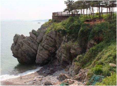
FIGURE 1. An anti-dip bedding rock slope facing Bohai Sea in China modified from Zhao et al. (2020).
In a two-dimensional model, rock layers in such failure behave like cantilever beams, which bend and deform under the combined action of gravity and external loads. Aydan and Kawamoto (1992) used the solid mechanics of cantilever beams to analyze this type of failure and proved it by base friction tests. Centrifugal tests and physical model tests under excavation at the toe area of the slope were also employed by many researchers (Adhikary et al., 1997; Zheng et al., 2019; Zheng et al., 2018a; Zhu et al., 2020). Based on these experimental results, they made some improvements for the analytical method and gave suggestions for the reinforcement of the slope. Meanwhile, Ning et al. (2019) and Li et al. (2019) used shaking tables to simulate this type of failure under seismic load. The shaking table was also utilized by Fan et al. (2016) to discuss the effect of the weak intercalation on the failure patterns of anti-dip bedding rock slopes. In addition to seismic load, Ning et al. (2021) and Gu and Huang (2016) suggested that the river downcutting should also be considered as an incentive of flexural toppling failure.
Numerical tools are also often employed by scholars and engineers to discuss and analyze flexural toppling failure, especially when the geological conditions of the slope were very complex. A finite element method was undertaken by Adhikary and Dyskin (2007) to analyze their physical model tests. Based on the distinct lattice spring model, Lian et al. (2018) analyzed flexural toppling failure by incorporating the gravity increase method. Zhang et al. (2020) tried to take the discontinuous deformation analysis (DDA) to simulate the tensile failure of blocks in toppling mode, but this method needs to add contacts at the failure surface in advance. As a commercial software commonly used in geotechnical engineering, the universal distinct element code (UDEC) was also utilized by a lot of researchers. For example, Alzo’ubi et al. (2010) used it to analyze the effect of tensile strength on the stability of slopes. Zheng et al. (2019a) used it to investigate the influence of rock bolts on the failure patterns. Weng et al. (2020) implemented a new failure criterion into this software to predict this failure.
As outlined above, many scholars have studied the mechanism of flexural toppling failure through theoretical analysis, model tests, and numerical simulation since its recognition as an important failure mode. However, the whole process of initiation, development, and penetration of the failure surface of the slope subjected to flexural toppling is still unclear. Compared to model tests, numerical simulations are less expensive and allow easy access to parameters that cannot be measured in model tests (Zhang et al., 2019; Wang et al., 2020; Yang et al., 2020; Meng et al., 2021; Yan et al., 2021). UDEC is ideal in modelling jointed rock masses since it can simulate both the behavior of the intact rock and the joints (Itasca, 2004). Furthermore, UDEC can simulate large deformations, such as tensile cracks between rock layers, which are a key feature of toppling failure. In this work, UDEC is thus used to investigate flexural toppling failure in rock slopes with various geometric and mechanical parameters. Two new parameters (displacement discontinuity and transition coefficient of failure surface) are introduced to present a further understanding of this type of failure. Moreover, based on the results of systematic numerical simulations, the whole evolution process of flexural toppling failure is discussed.
Universal Distinct Element Code Model
Model Configuration and Boundary Conditions
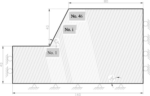
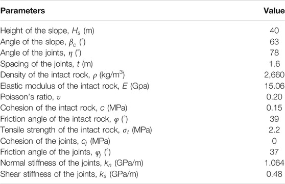
In order to understand the fundamental mechanism of flexural toppling in rock slopes, the basic calculation model used in this work is an ideal anti-dip bedding rock slope (Figure 2). The slope height and angle are 40 m and 63°, respectively, and the joint spacing and angle are 1.6 m and 78°, respectively. The geometric and mechanical parameters of the model are shown in Table 1.
Displacement constraints were used in the numerical simulation. Specifically, horizontal and vertical displacements at the base of the model were constrained while only the horizontal displacement was restricted at the lateral boundaries. A series of monitoring points (1 m apart) were laid out on the surface of the slope to monitor the horizontal and vertical displacement. The number of the measuring points is assigned as No.1 to No.46 starting from the toe of the slope to the top of the slope, as illustrated in Figure 2.
Constitutive Model and Model Parameters
The deformation and failure of anti-dip bedding rock slopes involve both intact rock and joints. In this work, two commonly used constitutive models, namely the Mohr-Coulomb model and the Coulomb slip model, were employed to describe the mechanical behavior of the intact rock and the joints, respectively.
Toppling failure mostly occurs in slopes with lithology or lithological combination of thin layered slate, schist, slate, sandstone, and muddy limestone (Tu et al., 2007; Amini et al., 2018; Zheng et al., 2018a; Huang et al., 2018; Zhang et al., 2018; García-Moya et al., 2019; Ning et al., 2021). This work relies on an actual limestone slope facing the Jingzhu Road in Southern China (Zheng et al., 2018a). Therefore, the lithology modelled in this work is limestone with low strength. The parameters used in the calculations are summarized in Table 1.
Influencing Factors Studied in the Simulation
In order to have a comprehensive understanding of the flexural toppling mechanism, four factors were studied in the simulations: angle of the joints, spacing of the joints, strength of the joints, and angle of the slope. Each factor includes 6 to 11 scenarios, and there are 26 models in total. It is important to note that a univariate analysis is used, i.e., when analyzing the influence of one parameter on the flexural toppling, the other parameters keep constant.
Results Analysis
In this section, distribution characteristics of the surface displacement and the plastic zone were studied to access the whole process of formation of the failure surface of the slope, and thus reveal the mechanism of flexural toppling failure. Moreover, the factors that play a controlling role in flexural toppling can be also found. Whether the surface displacement is perpendicular to the joints is a preliminary indication of flexural toppling. If it is perpendicular to the joints, the slope is likely to experience flexural toppling failure, otherwise the slope is experiencing sliding failure.
Effect of the Joint Angle
The prerequisite to the occurrence of toppling failure is that rock layers are misaligned with each other (Goodman and Bray, 1976). In the shallow part of the slope, the direction of the maximum principal stress is approximately parallel to the surface of the slope, as shown in Figure 3.
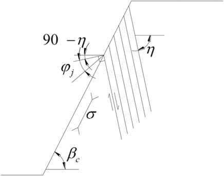
FIGURE 3. Toppling stability analysis in an anti-dip bedding rock slope (Goodman and Bray, 1976).
Only when the angle between the maximum principal stress and the normal to the joints is greater than the friction angle of the joints (ignoring the joint cohesion), mutual misalignment between adjacent rock layers is possible. It can be written as (Goodman and Bray, 1976):
where
The stability of rock slopes in six cases of
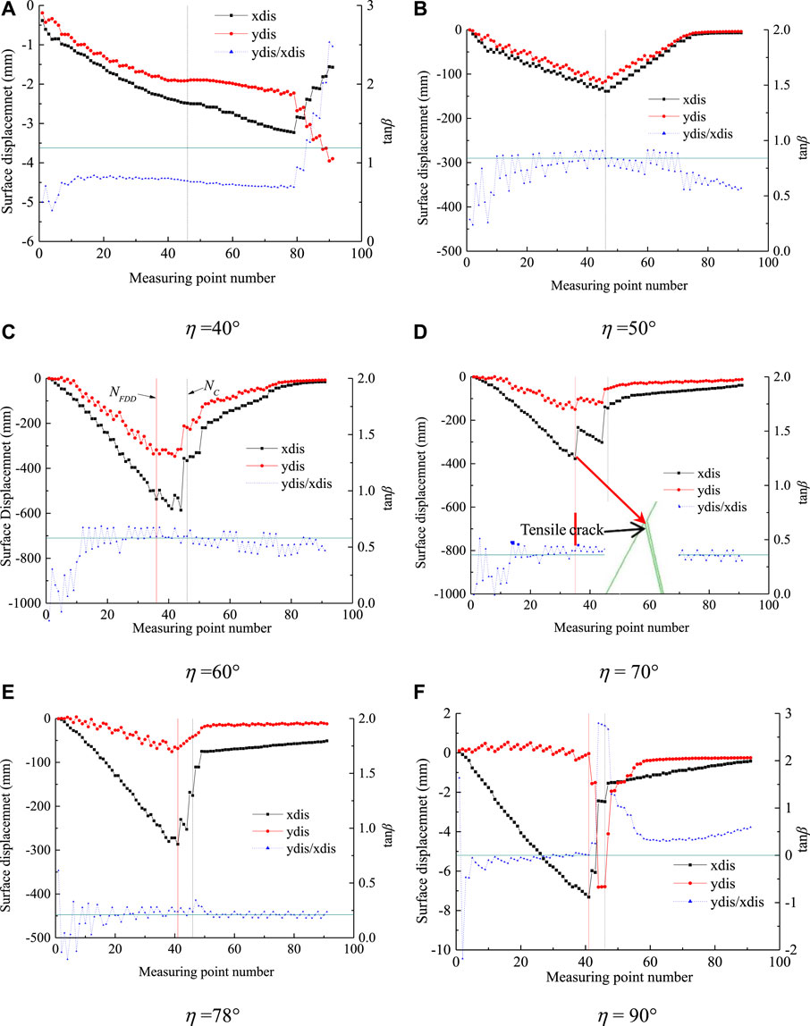
FIGURE 4. Surface displacement distribution of slope for different joint angles (
From Figure 4, we can find that, as the value of
Figure 3 indicates that no displacement discontinuities are found at
where
The variation in the value of transition coefficient of failure surface (
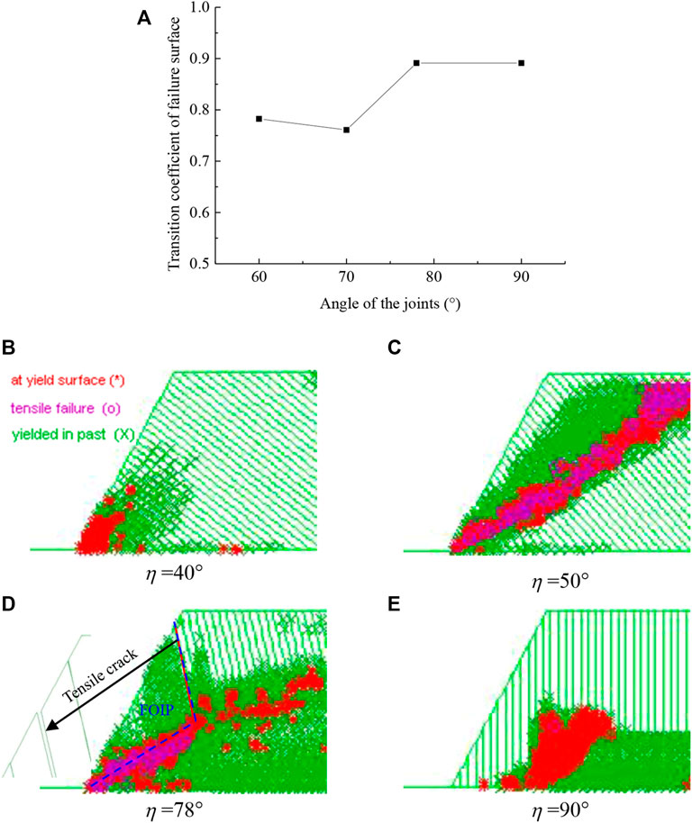
FIGURE 5. Failure distribution of the slope for different joint angles (
Figures 4B–E show the simulated plastic zone obtained using UDEC for different joint angles (
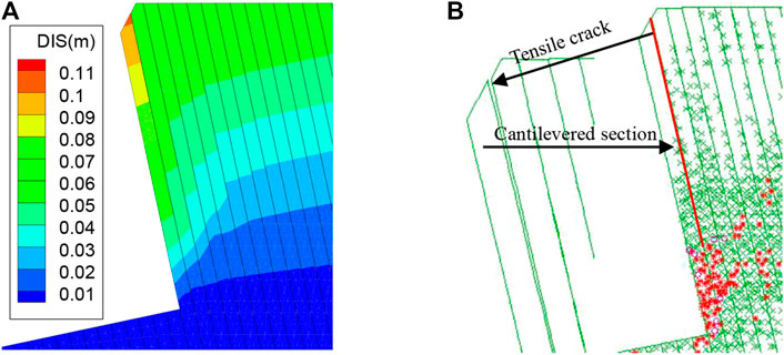
FIGURE 6. Displacement and plastic zone distribution of the upper rock layers after the formation of the FOIP. (A): Displacement distribution; (B) Plastic zone distribution.
Effect of the Joint Spacing
Joint spacing (
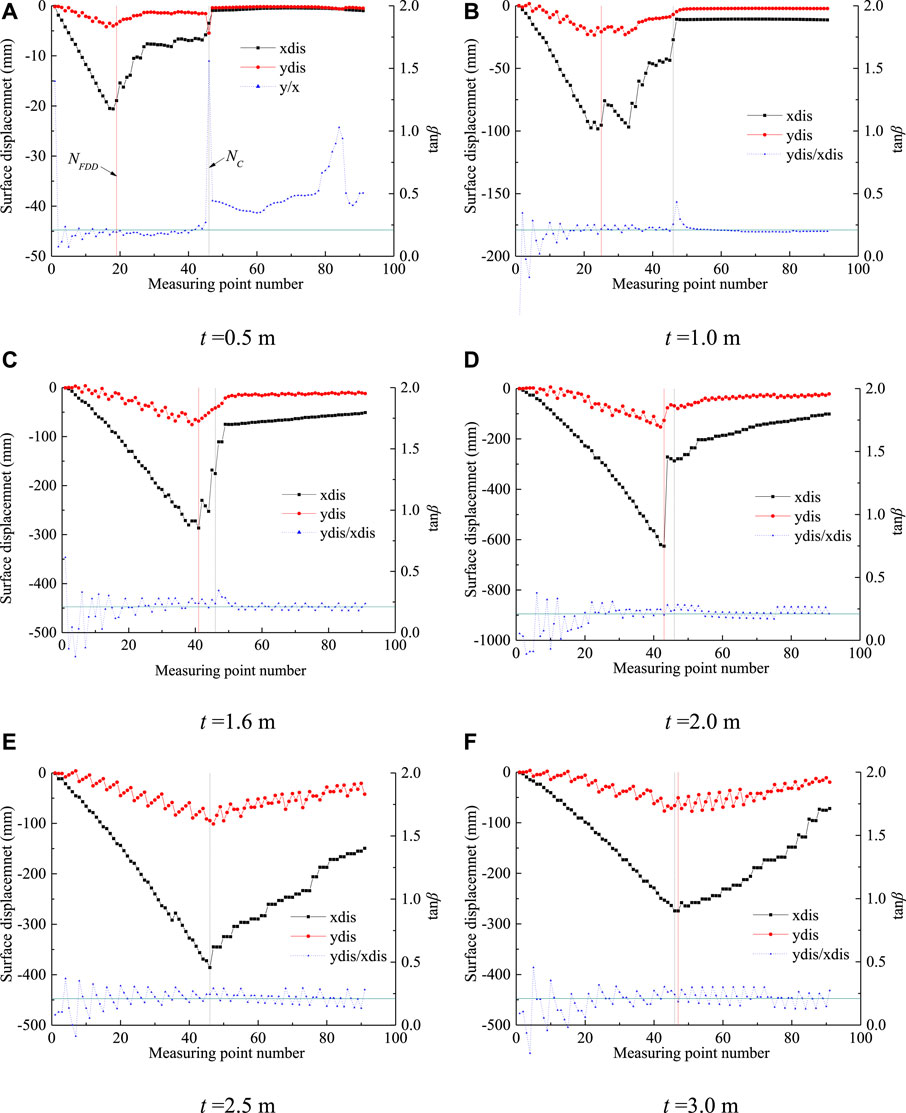
FIGURE 7. Surface displacement distribution of slope for different joint spacing (
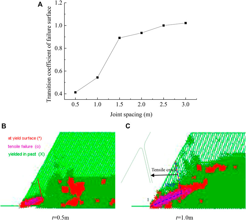
FIGURE 8. Failure distribution of the slope for different joint spacing (
It can be seen from Figure 7 that the surface displacement tends to increase and then decrease as the joint spacing increases and the maximum value occurs at the first displacement discontinuity. Except for the measuring points after the crest of the slope at
Figures 7B,C shows the simulated plastic zone obtained using UDEC for different joint spacing (
Effect of the Joint Strength
According to Eq. (1), to prevent the slope from toppling failure, the friction angle of the joints (
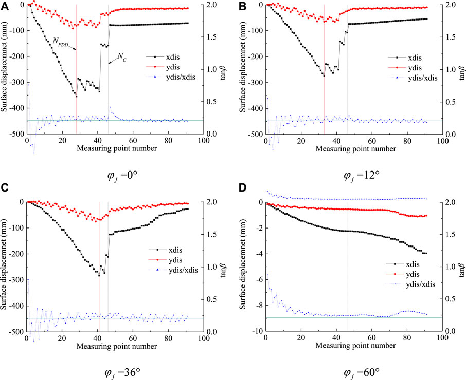
FIGURE 9. Surface displacement distribution of slope for different joint friction angles (
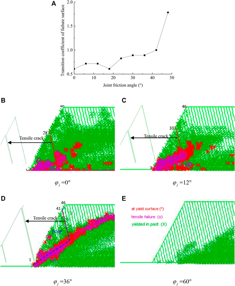
FIGURE 10. Failure distribution of the slope for different joint friction angles (
It can be seen that, when
Figures 9B–E show the simulated plastic zone obtained using UDEC for different joint friction angles (
Effect of the Cut Slope Angle
The angle of the slope (
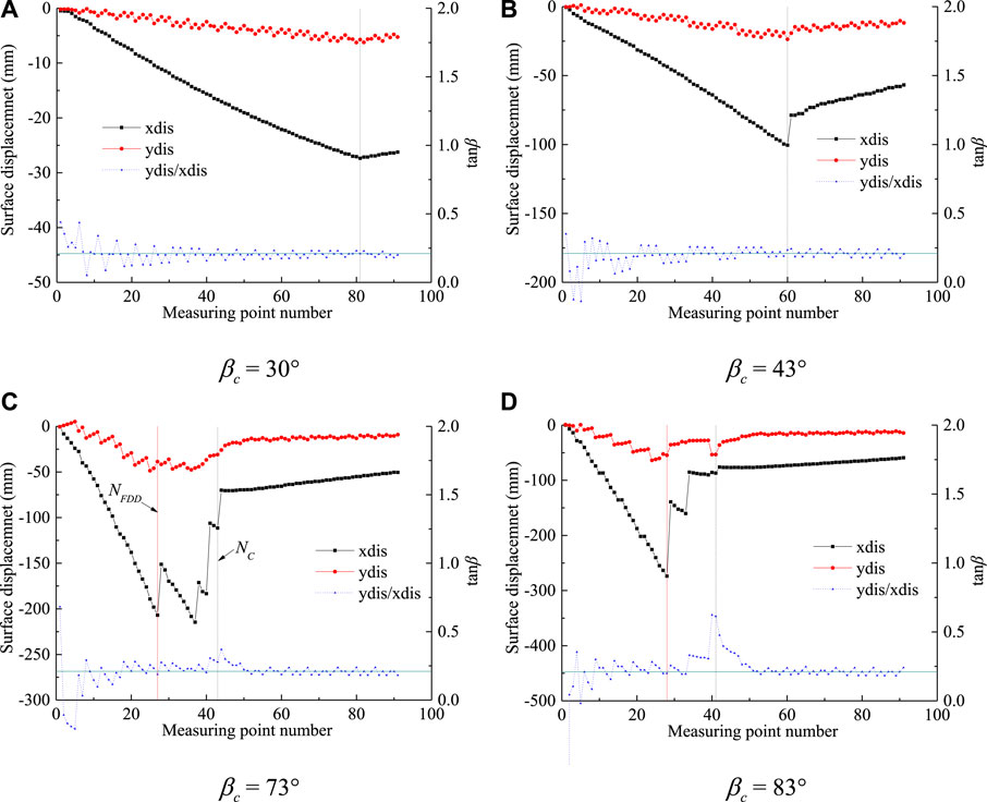
FIGURE 11. Surface displacement distribution of slope for different slope angles (
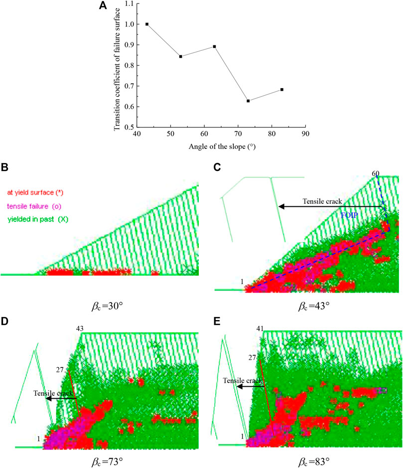
FIGURE 12. Failure distribution of the slope for different slope angles (
From Figure 11, it can be found that the surface displacement increase as the slope angle increases and the position of the maximum displacement point varies with
Figure 11 also shows that when
Figures 11B–E shows plots of the simulated plastic zone obtained using UDEC for different slope angles (
Discussion
Based on the results of the above numerical simulation, we can find that flexural toppling failure starts at the toe of the slope (Figure 13). Under the combined action of gravity and pushing forces from the upper rock layers, the layers at the toe area of the slope are the first to lose stability. The instability mode of each rock layer is controlled by the relative magnitude of its resistance to bending and shearing. If the bending resistance of a rock layer is greater than its shearing resistance, the layer undergoes shearing failure; otherwise, it undergoes flexural toppling failure (Zheng et al., 2018a; 2018b).
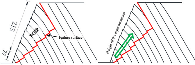
FIGURE 13. The failure zones of an anti-dip bedding rock slope. SZ: sliding zone; STZ: superimposed toppling zone; FOIP: first-order instability part.
Due to the small ratio of height to width of the rock layers around the toe of the slope, they have strong bending resistance and are therefore less prone to toppling failure. Under the combined action of gravity and pushing forces from the upper rock layers, the layers at the toe area often undergo shearing failure, forming the sliding zone (SZ). However, as the distance from the toe of the slope increases, the bending resistance of rock layers decreases due to the increase of the layer height. Then, the failure mode of rock layers gradually changes from shearing to flexural toppling, forming the superimposed toppling zone (STZ). Flexural toppling failure extends to the first displacement discontinuity (tensile crack), at which point a through plastic zone appears within the slope (Figure 5D). The through plastic zone referred to here is a penetration to the tensile crack rather than the surface of the slope, forming the boundaries of the first-order instability part (FOIP) together. After the occurrence of FOIP, the upper rock layers then have enough space for deformation that they undergo flexural toppling failure under the action of gravity, forming the independent toppling zone (ITZ), as shown in Figure 14.
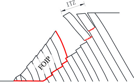
FIGURE 14. The failure process after the formation of the first-order instability part (FOIP). ITZ: independent toppling zone.
The failure surface of an anti-dip bedding rock slope is a complex stepped surface rather than a simple plane (Figure 13). Thus, finding the failure surface is a hard issue in carrying out stability assessment of this kind of slope. Limit equilibrium methods combined with optimization algorithms such as Genetic Algorithm and Bi-directional Evolutionary Structural Optimization (BESO) method have proved to be effective means of solving this problem (Zheng et al., 2020a, 2020b, 2021; Liu et al., 2021). Taking the first displacement discontinuity as the boundary, the lower rock layers are in close contact with each other despite the occurrence of interlayer slip, and the overall deformation is characterized as ‘superimposed cantilever beams’. However, for the upper rock layers, tensile cracks appear between adjacent layers, and the side forces is approximately zero. Each rock layer can be considered as an ‘independent cantilever beam’ (Figure 14). Thus, separate mechanical models need to be developed for these two parts of the rock layers (Zheng et al., 2018a).
Conclusion
In this work, the mechanism of flexural toppling failure in anti-dip bedding rock slopes is systematically studied using numerical simulation, and the main conclusions obtained are as follows:
1) The failure zone of rock slopes subjected to flexural toppling includes two parts: the first-order instability part (FOIP) and the independent toppling zone (ITZ). The FOIP can be further divided into two subzones: the sliding zone (SZ) and the superimposed toppling zone (STZ).
2) The mechanical behaviors of rock layers in the FOIP and ITZ are different. In the FOIP, rock layers are in close contact with each other and behave as “superimposed cantilever beams”. However, the layers in the ITZ behave as “superimposed cantilever beams” and can deform freely.
3) The occurrence of surface deformation discontinuities can be considered to be a precursor to flexural toppling failure and the first displacement discontinuity is the boundary between the FOIP and the ITZ.
4) The angle of the joints, spacing of the joints, strength of the joints, and angle of the slope have significant influences on the stability of anti-dip bedding rock slopes. However, their variations do not change the deformation and failure pattern of the slope.
Data Availability Statement
The original contributions presented in the study are included in the article/Supplementary Material, further inquiries can be directed to the corresponding author.
Ethics Statement
Written informed consent was obtained from the (individual(s) AND/OR minor(s)’ legal guardian/next of kin) for the publication of any potentially identifiable images or data included in this article’.
Author Contributions
YZ: Conceptualization, Methodology, Writing—original draft. RW: Writing—review and editing. CC: Supervision. FM: Writing—review and editing.
Funding
The research was financially supported by National Natural Science Foundation of China (Grant Nos. 12072358 and 12102315) and the Open Research Fund of the State Key Laboratory of Geomechanics and Geotechnical Engineering, Institute of Rock and Soil Mechanics, Chinese Academy of Sciences (Grant No. Z018009).
Conflict of Interest
The authors declare that the research was conducted in the absence of any commercial or financial relationships that could be construed as a potential conflict of interest.
Publisher’s Note
All claims expressed in this article are solely those of the authors and do not necessarily represent those of their affiliated organizations, or those of the publisher, the editors and the reviewers. Any product that may be evaluated in this article, or claim that may be made by its manufacturer, is not guaranteed or endorsed by the publisher.
Acknowledgments
We would like to acknowledge the reviewers and the editors for their comments and suggestions.
References
Adhikary, D. P., and Dyskin, A. V. (2007). Modelling of Progressive and Instantaneous Failures of Foliated Rock Slopes. Rock Mech. Rock Engng. 40 (4), 349–362. doi:10.1007/s00603-006-0085-8
Adhikary, D. P., Dyskin, A. V., Jewell, R. J., and Stewart, D. P. (1997). A Study of the Mechanism of Flexural Toppling Failure of Rock Slopes. Rock Mech. Rock Engng. 30 (2), 75–93. doi:10.1007/bf01020126
Alzo’ubi, A. K., Martin, C. D., and Cruden, D. M. (2010). Influence of Tensile Strength on Toppling Failure in Centrifuge Tests. Int. J. Rock Mech. Mining Sci. 47 (6), 974–982. doi:10.1016/j.ijrmms.2010.05.011
Amini, M., Sarfaraz, H., and Esmaeili, K. (2018). Stability Analysis of Slopes with a Potential of Slide-Head-Toppling Failure. Int. J. Rock Mech. Mining Sci. 112, 108–121. doi:10.1016/j.ijrmms.2018.09.008
Ashby, J. (1971). Sliding and Toppling Modes of Failure in Model and Jointed Rock Slopes. Dissertation of Master Degree. London: Royal School of Mines.
Aydan, O., and Kawamoto, T. (1992). The Stability of Slopes and Underground Openings against Flexural Toppling and Their Stabilisation. Rock Mech. Rock Engng. 25 (3), 143–165. doi:10.1007/bf01019709
De Freitas, M. H., and Watters, R. J. (1973). Some Field Examples of Toppling Failure. Géotechnique 23 (4), 495–513. doi:10.1680/geot.1973.23.4.495
Fan, G., Zhang, J., Wu, J., and Yan, K. (2016). Dynamic Response and Dynamic Failure Mode of a Weak Intercalated Rock Slope Using a Shaking Table. Rock Mech. Rock Eng. 49 (8), 3243–3256. doi:10.1007/s00603-016-0971-7
García-Moya, S. A., González-Galindo, J., and Olalla, C. (2019). Underdip Toppling Failure Mechanism: Case Study Retrospective Analysis and its Most Determinant Parameters. Int. J. Geomech. 19 (6), 1–13. doi:10.1061/(asce)gm.1943-5622.0001408
Goodman, R. E., and Bray, J. W. (1976). “Toppling of Rock Slopes,” in Rock Engineering for Foundations & Slopes (New York: ASCE), 201–234.
Gu, D., and Huang, D. (2016). A Complex Rock Topple-Rock Slide Failure of an Anaclinal Rock Slope in the Wu Gorge, Yangtze River, China. Eng. Geol. 208, 165–180. doi:10.1016/j.enggeo.2016.04.037
Huang, R., and Li, W. (2011). Formation, Distribution and Risk Control of Landslides in China. J. Rock Mech. Geotech. Eng. 3 (2), 97–116. doi:10.3724/sp.j.1235.2011.00097
Huang, D., Gu, D. M., Song, Y. X., Cen, D. F., and Zeng, B. (2018). Towards a Complete Understanding of the Triggering Mechanism of a Large Reactivated Landslide in the Three Gorges Reservoir. Eng. Geol. 238, 36–51. doi:10.1016/j.enggeo.2018.03.008
Li, L.-q., Ju, N.-p., Zhang, S., and Deng, X.-x. (2019). Shaking Table Test to Assess Seismic Response Differences between Steep Bedding and Toppling Rock Slopes. Bull. Eng. Geol. Environ. 78, 519–531. doi:10.1007/s10064-017-1186-1
Lian, J.-J., Li, Q., Deng, X.-F., Zhao, G.-F., and Chen, Z.-Y. (2018). A Numerical Study on Toppling Failure of a Jointed Rock Slope by Using the Distinct Lattice spring Model. Rock Mech. Rock Eng. 51 (2), 513–530. doi:10.1007/s00603-017-1323-y
Liu, T., Ding, L., Meng, F., Li, X., and Zheng, Y. (2021). Stability Analysis of Anti-dip Bedding Rock Slopes Using a Limit Equilibrium Model Combined with Bi-directional Evolutionary Structural Optimization (Beso) Method. Comput. Geotechn. 134 (4), 104116. doi:10.1016/j.compgeo.2021.104116
Meng, F., Song, J., Wong, L. N. Y., Wang, Z., and Zhang, C. (2021). Characterization of Roughness and Shear Behavior of Thermally Treated Granite Fractures. Eng. Geol. 293, 106287. doi:10.1016/j.enggeo.2021.106287
Ning, Y., Zhang, G., Tang, H., Shen, W., and Shen, P. (2019). Process Analysis of Toppling Failure on Anti-dip Rock Slopes under Seismic Load in Southwest China. Rock Mech. Rock. Eng. 52 (11), 4439–4455. doi:10.1007/s00603-019-01855-z
Ning, Y., Tang, H., Zhang, G., Smith, J. V., Zhang, B., Shen, P., et al. (2021). A Complex Rockslide Developed from a Deep-Seated Toppling Failure in the Upper Lancang River, Southwest China. Eng. Geol. 293, 106329. doi:10.1016/j.enggeo.2021.106329
Tu, X. B., Dai, F. C., Lu, X. J., and Zhong, H. Y. (2007). Toppling and Stabilization of the Intake Slope for the Fengtan Hydropower Station Enlargement Project, Mid-south china. Eng. Geol. 91 (2-4), 152–167. doi:10.1016/j.enggeo.2007.01.009
Wang, Z.-F., Shen, S.-L., Modoni, G., and Zhou, A. (2020). Excess Pore Water Pressure Caused by the Installation of Jet Grouting Columns in clay. Comput. Geotechn. 125, 103667. doi:10.1016/j.compgeo.2020.103667
Weng, M.-C., Chang, C.-Y., Jeng, F.-S., and Li, H.-H. (2020). Evaluating the Stability of Anti-dip Slate Slope Using an Innovative Failure Criterion for Foliation. Eng. Geol. 275, 105737. doi:10.1016/j.enggeo.2020.105737
Yan, C., Zheng, Y., Huang, D., and Wang, G. (2021). A Coupled Contact Heat Transfer and thermal Cracking Model for Discontinuous and Granular media. Comput. Methods Appl. Mech. Eng. 375, 113587. doi:10.1016/j.cma.2020.113587
Yang, Y., Xu, D., Liu, F., and Zheng, H. (2020). Modeling the Entire Progressive Failure Process of Rock Slopes Using a Strength-Based Criterion. Comput. Geotechn. 126, 103726. doi:10.1016/j.compgeo.2020.103726
Zhang, G., Wang, F., Zhang, H., Tang, H., Li, X., and Zhong, Y. (2018). New Stability Calculation Method for Rock Slopes Subject to Flexural Toppling Failure. Int. J. Rock Mech. Mining Sci. 106, 319–328. doi:10.1016/j.ijrmms.2018.04.016
Zhang, C., Pu, C., Cao, R., Jiang, T., and Huang, G. (2019). The Stability and Roof-Support Optimization of Roadways Passing through Unfavorable Geological Bodies Using Advanced Detection and Monitoring Methods, Among Others, in the Sanmenxia Bauxite Mine in China's Henan Province. Bull. Eng. Geol. Environ. 78 (7), 5087–5099. doi:10.1007/s10064-018-01439-1
Zhang, Y., Wang, J., Zhao, J. X., Chen, G., Yu, P., and Yang, T. (2020). Multi-spring Edge-To-Edge Contact Model for Discontinuous Deformation Analysis and its Application to the Tensile Failure Behavior of Rock Joints. Rock Mech. Rock Eng. 53, 1243–1257. doi:10.1007/s00603-019-01973-8
Zhao, W., Wang, R., and Nian, T. (2020). Stability Analysis of Anti-dip Rock Slopes with Flexural Toppling Failure Based on Deformation Compatibility. Rock Mech. Rock Eng. 53, 3207–3221. doi:10.1007/s00603-020-02098-z
Zheng, D., Wang, Q. Y., Mao, F., and Su, H. (2019). Centrifuge Model Test Study on Key hazard-inducing Factors of Deep Toppling Deformation and Disaster Patterns of Counter-tilt Layered Rock Slopes. Chin. J. Rock Mech. Eng. 38 (10), 1954–1963. (in Chinese). doi:10.13722/j.cnki.jrme.2018.1484
Zheng, Y., Chen, C., Liu, T., Xia, K., and Liu, X. (2018a). Stability Analysis of Rock Slopes against Sliding or Flexural-Toppling Failure. Bull. Eng. Geol. Environ. 77 (4), 1383–1403. doi:10.1007/s10064-017-1062-z
Zheng, Y., Chen, C., Liu, T., Zhang, H., Xia, K., and Liu, F. (2018b). Study on the Mechanisms of Flexural Toppling Failure in Anti-inclined Rock Slopes Using Numerical and Limit Equilibrium Models. Eng. Geol. 237, 116–128. doi:10.1016/j.enggeo.2018.02.006
Zheng, Y., Chen, C., Liu, T., Song, D., and Meng, F. (2019a). Stability Analysis of Anti-dip Bedding Rock Slopes Locally Reinforced by Rock Bolts. Eng. Geol. 251, 228–240. doi:10.1016/j.enggeo.2019.02.002
Zheng, Y., Chen, C., Liu, T., Zhang, H., and Sun, C. (2019b). Theoretical and Numerical Study on the Block-Flexure Toppling Failure of Rock Slopes. Eng. Geol. 263, 105309. doi:10.1016/j.enggeo.2019.105309
Zheng, Y., Chen, C., Meng, F., Liu, T., and Xia, K. (2020a). Assessing the Stability of Rock Slopes with Respect to Flexural Toppling Failure Using a Limit Equilibrium Model and Genetic Algorithm. Comput. Geotechn. 124, 103619. doi:10.1016/j.compgeo.2020.103619
Zheng, Y., Chen, C., Meng, F., Zhang, H., Xia, K., and Chen, X. (2020b). Assessing the Stability of Rock Slopes with Respect to Block-Flexure Toppling Failure Using a Force-Transfer Model and Genetic Algorithm. Rock Mech. Rock Eng. 53, 3433–3445. doi:10.1007/s00603-020-02122-2
Zheng, Y., Chen, C., Liu, T., and Ren, Z. (2021). A New Method of Assessing the Stability of Anti-dip Bedding Rock Slopes Subjected to Earthquake. Bull. Eng. Geology. Environ. 80 (4), 1–18. doi:10.1007/s10064-021-02188-4
Zhu, C., He, M., Karakus, M., Cui, X., and Tao, Z. (2020). Investigating Toppling Failure Mechanism of Anti-dip Layered Slope Due to Excavation by Physical Modelling. Rock Mech. Rock Eng. 53 (11), 5029–5050. doi:10.1007/s00603-020-02207-y
Glossary
List of Symbols
FOIP First-order instability part of the slope
Keywords: rock slopes, flexural toppling failure, discrete element method, stability analysis, displacement discontinuity
Citation: Zheng Y, Wang R, Chen C and Meng F (2021) Analysis of Flexural Toppling Failure in Rock Slopes Using Discrete Element Method. Front. Earth Sci. 9:773088. doi: 10.3389/feart.2021.773088
Received: 09 September 2021; Accepted: 22 September 2021;
Published: 06 October 2021.
Edited by:
Zetian Zhang, Sichuan University, ChinaReviewed by:
Zhi-feng Wang, Chang’an University, ChinaZhizhen Zhang, China University of Mining and Technology, China
Copyright © 2021 Zheng, Wang, Chen and Meng. This is an open-access article distributed under the terms of the Creative Commons Attribution License (CC BY). The use, distribution or reproduction in other forums is permitted, provided the original author(s) and the copyright owner(s) are credited and that the original publication in this journal is cited, in accordance with accepted academic practice. No use, distribution or reproduction is permitted which does not comply with these terms.
*Correspondence: Fei Meng, ZmVpbWVuZ0B3aHV0LmVkdS5jbg==
 Yun Zheng
 Runqing Wang1,2
 Fei Meng